

Days Strider MD 3, Strider MD 4 Operating Manual

NURSING BEDSPFLEGEBETTEN
STRIDER
OPERATING MANUAL
MD 3 and MD 4
3-wheel and 4-wheel version
Order number: E1-04-049-001


3
Issued: 24.02.2005
STRIDER MD
Introduction
If you have any other questions about this scooter please contact
your retailer or supplier .
With the Strider MD, you hav e no w purchased a product which has
been manufactured in accordance with the newest technical
capabilities and based on the highest operating comfort.
We have placed great value on the simplest possible operation and
long service life in both construction and material selection.
A large variety of useful accessories rounds off our range in addition
to the Strider.
This Operating Manual assumes that the suitability of the user for
Strider usage has been discussed with a doctor, therapist and/or
dealer before operation.
The operating manual will help you get to know the function of our
Strider and, in addition, describes
• operation
• care and maintenance
• repair
The manual has been drawn up using information available at the time
of printing with regard to construction and operation of the Strider.
We reserve the right to make changes due to technical improvements.

4
Issued: 24.02.2005
STRIDER MD
Contents
1.0 Sa fety inst ruction s .................................................................................8
1.1 Symbols used..............................................................................8
1.2 Intended use ................................................................................8
1.3 General Information .....................................................................9
1.4 Safety when driving ................................................................... 10
1.5 Safety during transport, assembly and maintenance..................11
1.6 Safety when handling batteries ..................................................12
1.7 Safety - information about electronics........................................ 1 2
2.0 Ve rsions............................................................................................13
3.0 Extent o f delivery .............................................................................13
4.0 Components ..................................................................................... 14
4.1 The Strider................................................................................. 14
4.2 The dashboard - displays and controls.......................................14
5.0 Brie f instru ctions .............................................................................1 5
5.1 Driving the Strider ......................................................................15
5.2 T ransporting the Strider.............................................................. 17
6.0 Setting up the Strider ...................................................................... 19
6.1 Adjusting the seat height ........................................................... 1 9
6.2 Adjusting the seat position - standard seat ................................23
6.2.1 Adjusting the distance between seat and tiller ................ 2 3
6.2.2 Adjusting the armrest width ............................................ 23
6.2.3 Adjusting the armrest height ...........................................2 4
6.3 Adjusting the seat position - captain´s seat ...............................2 5
6.3.1 Adjusting the distance between seat and tiller ................ 2 5
6.3.2 Adjusting the armrest width ............................................ 25
6.3.3 Adjusting the armrest height ...........................................2 5
6.3.4 Adjusting the backrest inclination ................................... 26
6.3.5 Adjusting the headrest hight ...........................................27
6.4 Adjusting the tiller angle.............................................................27
7.0 Information about safe Strider driving ........................................... 28
7.1 Driving up inclines and down slopes .......................................... 28
7.2 Overcoming obstacles ...............................................................29
7.2.1 Driving Information – Overcoming kerbs .........................31
7.3 Overload protection - motor protection .......................................32
7.4 Battery charging state = driving range........................................ 33
7.4.1 Battery charging state ....................................................33
7.4.2 Driving range ..................................................................34
7.4.3 Overdischarge protection - battery protection..................35
8.0 Driving the Strider ...........................................................................36
8.1 Getting on and off ...................................................................... 36

5
Issued: 24.02.2005
STRIDER MD
Contents
8.2 Seat belt - adjusting for length and putting on ............................37
8.3 Turning the seat ......................................................................... 38
8.4 Switching the strider on .............................................................38
8.4.1 Operation indicator and fault display ............................... 38
8.5 Adjusting the speed ...................................................................39
8.6 Before driving ............................................................................39
8.7 Driving .......................................................................................40
8.8 Brakes ....................................................................................... 40
8.8.1 Using the motor brake ....................................................40
8.8.2 Using the handbrake (4-wheel version only) ....................41
8.9 Indicating ................................................................................... 41
8.1 0 Switching on the headlights .......................................................41
8.11 Using the horn ...........................................................................42
8.1 2 Switching off / parking the Strider .............................................. 42
9.0 Hazard lamps ................................................................................... 42
10. 0 Pushing the Strider.......................................................................... 43
11.0 Attaching the shopping basket ....................................................... 43
12.0 Charging the batteries .....................................................................44
12. 1 Preparing the battery charger ..................................................... 44
12. 2 Charging the batteries ................................................................ 45
12. 3 After charging ............................................................................46
13. 0 Things to know ................................................................................47
13. 1 The battery charger - functioning principle.................................. 47
13.2 The batteries.............................................................................. 47
13.2.1 What are batteries for cyclic use?................................... 4 7
13.2.2 When do the batteries achieve their maximum
performance?.................................................................. 47
13.2.3 How do I make sure the batteries achieve their
best service life? ............................................................47
13. 3 The auto switch-off .................................................................... 48
13. 4 Lighting - 4 wheel version........................................................... 48
13. 5 Anti tipping wheels.....................................................................48
13.6 Wheels and tyres ....................................................................... 48
13. 7 The drive unit............................................................................. 49
13. 8 The drive (a-c) ........................................................................... 49
13. 9 The control unit..........................................................................49
13.10 Brakes on the strider ...............................................................50
13.10.1The motor brake .......................................................... 50
13.10.2The handbrake (4 wheel version) .................................50
13.11 Driver´s licence........................................................................ 50

6
Issued: 24.02.2005
STRIDER MD
Contents
13.12 Insurance................................................................................. 50
13.13 Approval for road traffic use.....................................................50
14. 0 Transporting the strider ................................................................... 51
14.1 T ransport information ................................................................. 51
14. 2 Transporting the complete scooter .............................................51
14. 3 Preparation f or transport - separating components .....................51
14.3.1 Working step summary ................................................... 52
14.3.2 Removing the seat..........................................................52
14.3.3 Removing the rear panelling............................................ 52
14.3.4 Removing the batteries ................................................... 53
14.3.5 Folding the tiller down .....................................................53
14.3.6 Disengaging the drive unit from the chassis.................... 5 3
14. 4 After T ransport - Reassembly..................................................... 55
14.4.1 Engaging the drive unit to the chassis ............................5 5
14.4.2 Folding the tiller up ......................................................... 57
14.4.3 Reinserting the batteries.................................................57
14.4.4 Fixing the rear panelling ..................................................58
14.4.5 Fitting the seat ...............................................................58
15.0 Cleaning ...........................................................................................59
16.0 Maintenance and Inspection ........................................................... 60
16. 1 Daily maintenance bef ore start of journey ..................................60
16. 2 Weekly inspections / tyre pressure ............................................60
16. 3 Annual inspection - inspection timetable .................................... 61
17.0 Tr oub leshooting............................................................................... 65
17.1 Before troubleshooting ............................................................... 65
17.2 Troubleshootimg......................................................................... 65
17. 3 Operation indicator blink codes ..................................................68
17.3.1 Blink speed..................................................................... 68
17.3.2 Error message blink sequences...................................... 68
18.0 Repairs .............................................................................................70
18. 1 Information about safety at work................................................70
18.2 Tools .......................................................................................... 70
18. 3 Mechanics .................................................................................71
18.3.1 Adjusting the drive lock clamping bolt.............................71
18.3.2 Wheels - removal and replacement - 3-wheel version......73
18.3.3 Wheels - removal and replacement - 4-wheel version......74
18.3.4 Replacing the inner tube / tyre ........................................76
18. 4 Lighting - 3 wheel version........................................................... 77
18.4.1 Replacing bulb in headlight ............................................. 77
18.4.2 Replacing bulbs in front indicators .................................. 78

7
Issued: 24.02.2005
STRIDER MD
Contents
18.4.3 Replacing bulbs in rear lights and rear indicators ............ 78
18. 5 Lighting - 4 wheel version........................................................... 79
18.5.1 Replacing bulbs in headlights and rear light .................... 79
18.5.2 Replacing bulbs in front/rear indicators ...........................80
18.6 Fuses ........................................................................................ 81
18.6.1 Strider fuses ................................................................... 81
18.6.2 Battery charger fuse....................................................... 8 2
18.7 Batteries .................................................................................... 82
18.7.1 Disposal of used or damaged batteries ...........................82
18.7.2 Refitting battery cables ................................................... 83
19.0 T emporary storage ........................................................................... 84
20.0 Appendix ..........................................................................................84
20.1 Nameplate ................................................................................. 84
20.2 Specifications ............................................................................ 85
20.2.1 General data ...................................................................85
20.2.2 Dimensions 3-wheel version ...........................................86
20.2.3 Dimensions 4-wheel version ...........................................87
20. 3 Torque for fixing scre ws .............................................................8 8
20. 4 Disposing of the scooter ............................................................ 8 8
21.0 W arranty information .......................................................................89
22. 0 Annual inspections carried out ....................................................... 90
8
Issued: 24.02.2005
STRIDER MD
Safety information
This instruction manual contains the following symbols which are used
to highlight special hazards in dealing with the product or information for
simplifying the handling.
Caution!
This symbol identifies safety information which notifies you of
hazards when dealing with the product.
NOT E
You will also find information about dealing with the product
under this symbol.
The Days Healthcare scooter is constructed for use both indoors and
outdoors (Class B, European standard EN 12 184).
It is intended to increase the mobility of persons who are both
physically and mentally capable of assessing any driving situations
correctly and reacting correspondingly to them at any time.
The MD 3 and MD4 models are classified as an “invalid carriage” for use
indoors, on pavements, footpaths, pedestrian zones and areas free
from motor traffic.
They must not be driven on public roads with the exception of crossing
or when no pavements are available.
1.0 Safety instructions
1.1 Symbols used
1.2 Intended use
9
Issued: 24.02.2005
STRIDER MD
Safety information
Read the entire operating manual thoroughly before using the
Strider!
Ensure that:
• the operating manual is read by all people who drive, care for and
service the scooter.
• all persons who drive, care for , service or repair the scooter hav e
access to the operating manual at any time.
Any damages resulting from nonobservance of this operating manual
are excluded from the guarantee.
Risk of accidents!
• Do NO T use the scooter if y our driving capability is impaired
through consumption of medicine or alcohol.
• Only use the scooter for its correct intended use.
• Only use the scooter when it is in perf ect working order .
• If any breakdo wns occur , stop using the scooter immediately
and secure it against unauthorized use.
• It is imperative that you always rectify any faults which
could influence the function and safety of the scooter
immediately.
• Observe maximum loading = see Specifications
• Only use accessories and spare parts authorized by
Days Healthcare.
• The scooter is only authorized f or transport of one person.
• Do not carry out any seat adjustments while driving.
Tipping hazard!
• Do not adjust the seat if the scooter is standing on an incline.
• Do not lean out over the armrest to the sides or over the
backrest to the rear .
1.3 General Information
10
Issued: 24.02.2005
STRIDER MD
Safety information
1.4 Safety when driving
Tipping hazard!
• Do not carry out any seat adjustments while driving.
• Only drive over obstacles and up kerbstones at the lowest
point and at right angles.
• Avoid sudden changes of direction and speed.
• Avoid steep gr adients where there is a danger of skidding
(ice, snow, wet surfaces etc.).
• Avoid loose surf aces whose characteristics you are not ab le
to assess (woodlands, turf, beaches, gravel etc.)
• Always drive straight up and down gradients - do not drive in
zigzags.
• Do not turn around on inclines.
• Do not drive down steps.
• Do not drive backwards down gradients, stairs or kerbstones,
or over obstacles.
Risk of accidents!
• Check correct functioning of the brakes and lighting unit
(indicators, headlights) before e very journey .
• Always use lights when visibility is restricted, either by day
or by night.
• Check the tyre air pressure regularly .
• Always use the seat belts when driving.
• Do not switch the scooter off while driving.
• Do not drive up or down gradients which are too steep, over
obstacles on gradients or up and down ramps.
Observe maximum climb angle = see Specifications
• Only drive through restricted widths, around bends, inclines
and ramps with reduced suitable speed.
• Only drive up or down inclines when the backrest has been
adjusted to vertical.
• Don´t drive too close to open waters.
11
Issued: 24.02.2005
STRIDER MD
Safety information
Danger due to unintentional movement!
• Always turn the scooter off using the keyswitch if you:
- want to get on or off
- intend to stop for long periods
- are putting the scooter awa y.
1.5 Safety during transport, assembly and maintenance
Injury hazard due to improper assembly!
• Ensure that all components in the Scooter have been
correctly assembled.
• After assembly, check that all locking devices are holding
correctly.
Clamping and crushing hazard!
Increased hazards due to clamping or crushing result due to the
high component weight (such as batteries) during preparation
for transport and maintenance work.
• Always carry out any work to be done with great care.
• Always try to get help from a second person, especially when
stowing parts for transport.
• Only carry out any work described if you are used to working
with the tools required.
• Only carry out work using suitable tools.
If the scooter is transported in the vehicle when fully
assembled:
- no persons may sit on the scooter during loading!
- no persons may sit on the scooter during transport!
Accident hazard due to incorrectly bolted connections!
• If bolted connections have self-locking nuts, ensure that
these are replaced when reassembling.
• Do not replace self-locking nuts with normal nuts.
• If bolted connections have lock washers, check lock washers
when reassembling and replace if necessary .
12
Issued: 24.02.2005
STRIDER MD
Safety information
Risk of accidents!
• Only use the original battery charger (included in delivery).
• Let your dealer replace your battery .
• Only use batteries as detailed in the chapter entitled
“Specifications”.
• Observe warning information given by the battery
manufacturer.
• Batteries are extremely heavy.
Burn hazard due to damaged batteries!
Batteries discharging acid can lead to serious burns.
• Do not touch damaged batteries with your bare hands. Use
rubber gloves!
• If acid should contact your skin, wash the affected area
immediately with plenty of water and contact a doctor .
• If acid should come in contact with your eyes, rinse them out
immediately with lots of water and visit a doctor .
• Always change any clothing soiled with battery acid
immediately.
1.7 Safety - information about electronics
Accident hazard due to failures!
Radio, tele vision, radio transmission de vices and mobile phones
produce electromagnetic fields. These can negatively influence
the scooter electronics functions.
• Do not drive close to strong radio or television transmitters
(transmitter masts).
• Switch the scooter off if you are using your mobile phone.
1.6 Safety when handling batteries
Fire hazard!
• Do not cover the battery charger and ventilation slot while
charging batteries.
• Only use the battery charger in well-ventilated areas.
Failure in outside devices!
The Scooter produces an electromagnetic field which can have
a negative influence on the function of any other electrical
devices in the immediate surroundings (such as medical
devices, radio receivers, cellular phones).
13
Issued: 24.02.2005
STRIDER MD
Versions
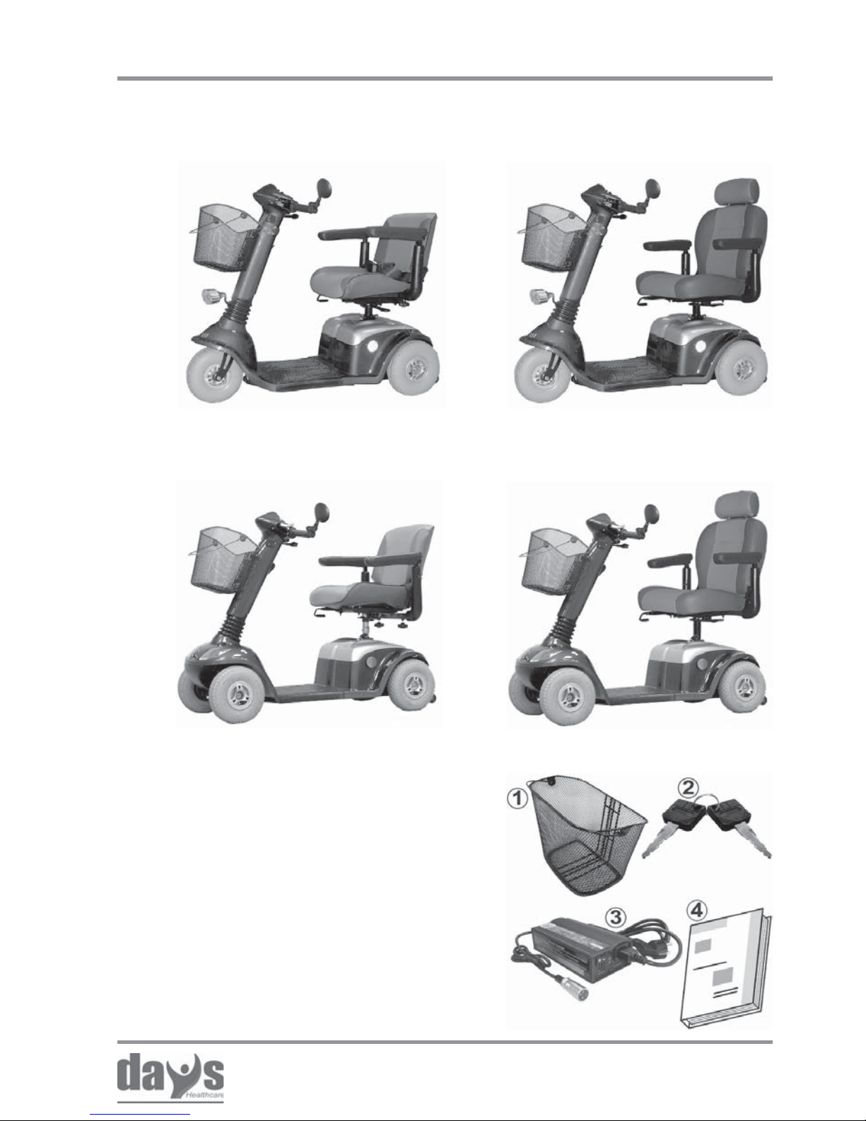
2.0 Versions
The following items are included in
delivery in addition to the Strider:
1. Shopping basket
2. Two vehicle keys for switching
the Strider on
3. Battery Charger
4. Operating Manual
3.0 Extent of delivery
3-wheel version with standard
seat
4-wheel version with
standard seat
3-wheel version with captain’ s
seat
4-wheel version with captain’ s
seat
14
Issued: 24.02.2005
STRIDER MD
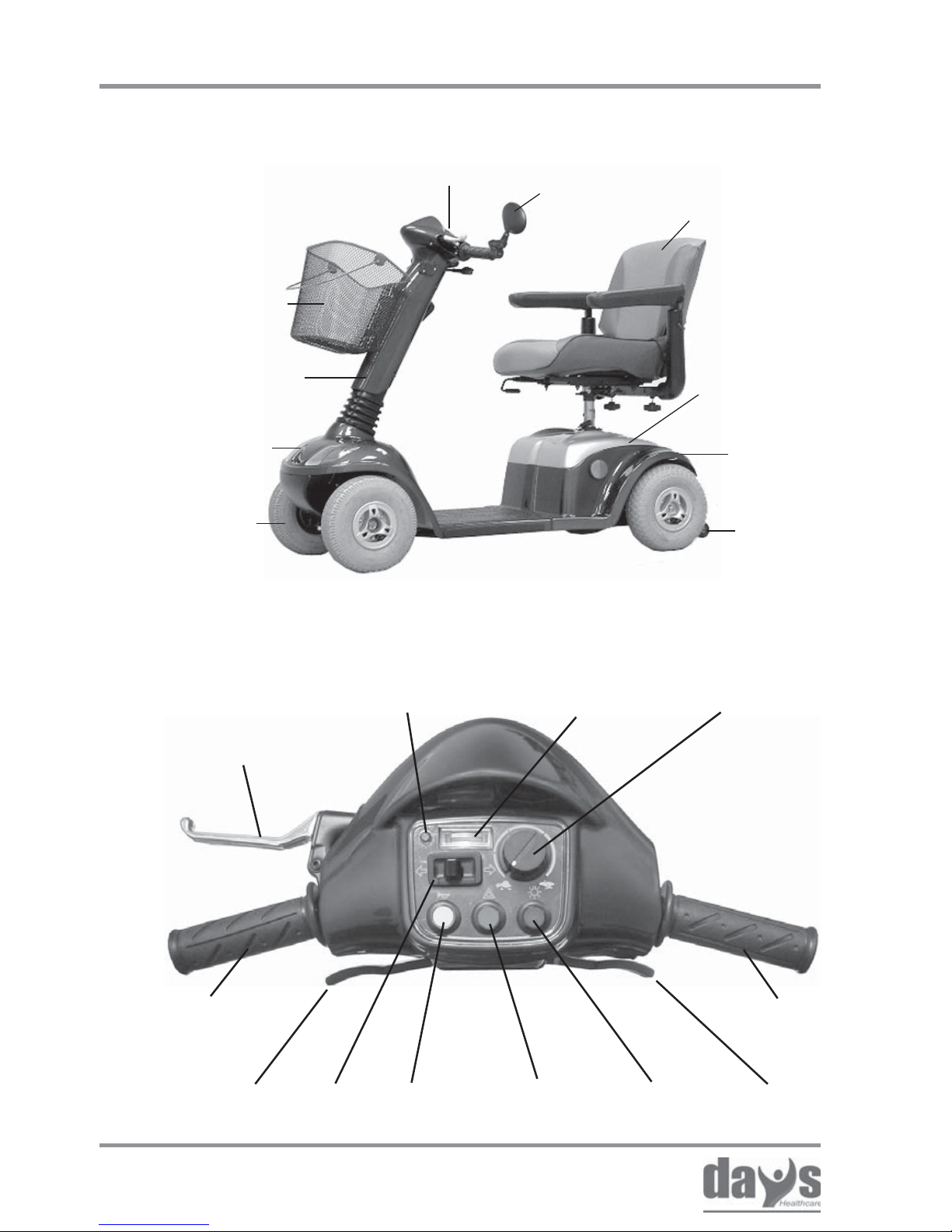
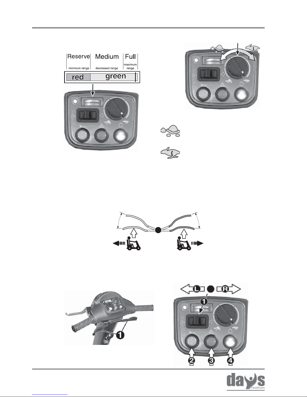
Operation indicator
(fault display)
Components
4.0 Components
4.2 The dashboard - displays and controls
Brake lever for
handbrake and
wheel lock
(4-wheel version
only)
Speed
contoller
Battery charge
display
Drive lever
(reverse)
Drive lever
(forwards)
Horn
button
Hazard
indicator switch
Headlight
switch
Indicator
switch
Anti
tipper
Shopping
basket
Tiller
Steering
wheel
Indicators and
headlight
Dashboard
with controls
Indicators
and rear
light
Drive unit
covers
Rear view
mirror
Seat unit with
armrests
Handle Handle
4.1 The Strider
15
Issued: 24.02.2005
STRIDER MD
ON
Brief instructions
5.0 Brief instructions
The following brief instructions should enable people to quickly get used
to operating the scooter after a long period of non-use and to refresh
existing knowledge of operation.
It is imperative that you follow the instructions given in the main
manual!
1.) Turn the seat to the outside.
NOTE
Before starting driving, adjust the seat height, the
backrest and the armrests to a comfortable position.
Your specialist dealer would be very glad to help.
5.1 Driving the Strider
4.) Switch on the Strider
2.) Get in - turn the seat in the
direction of travel
3.) Fasten the seat belt.
16
Issued: 24.02.2005
STRIDER MD
1
= lowest possible driving
speed (approx. 1.5 mph)
= highest possible driving
speed (approx. 4 mph)
The drive lever position controls the
speed variably right up to maximum
driving speed.
Reverse
Forwards
Max. driving speed
Max. driving speed
Standstill
(brake engaged)
Standstill
(brake engaged)
5.) Check the battery
charging state
6.) Set the maximum speed
7.) Driving
Operate the drive lever slowly until the required speed has been reached
8.) Braking = release drive
lever (1)
9.) Direction indicators (1), Horn (2)
Lights (3) / Hazard lamps (4)
Brief instructions
17
Issued: 24.02.2005
STRIDER MD
5.2 T ransporting the Strider
5.) Remove the battery belts and
batteries
6.) Fold the tiller down
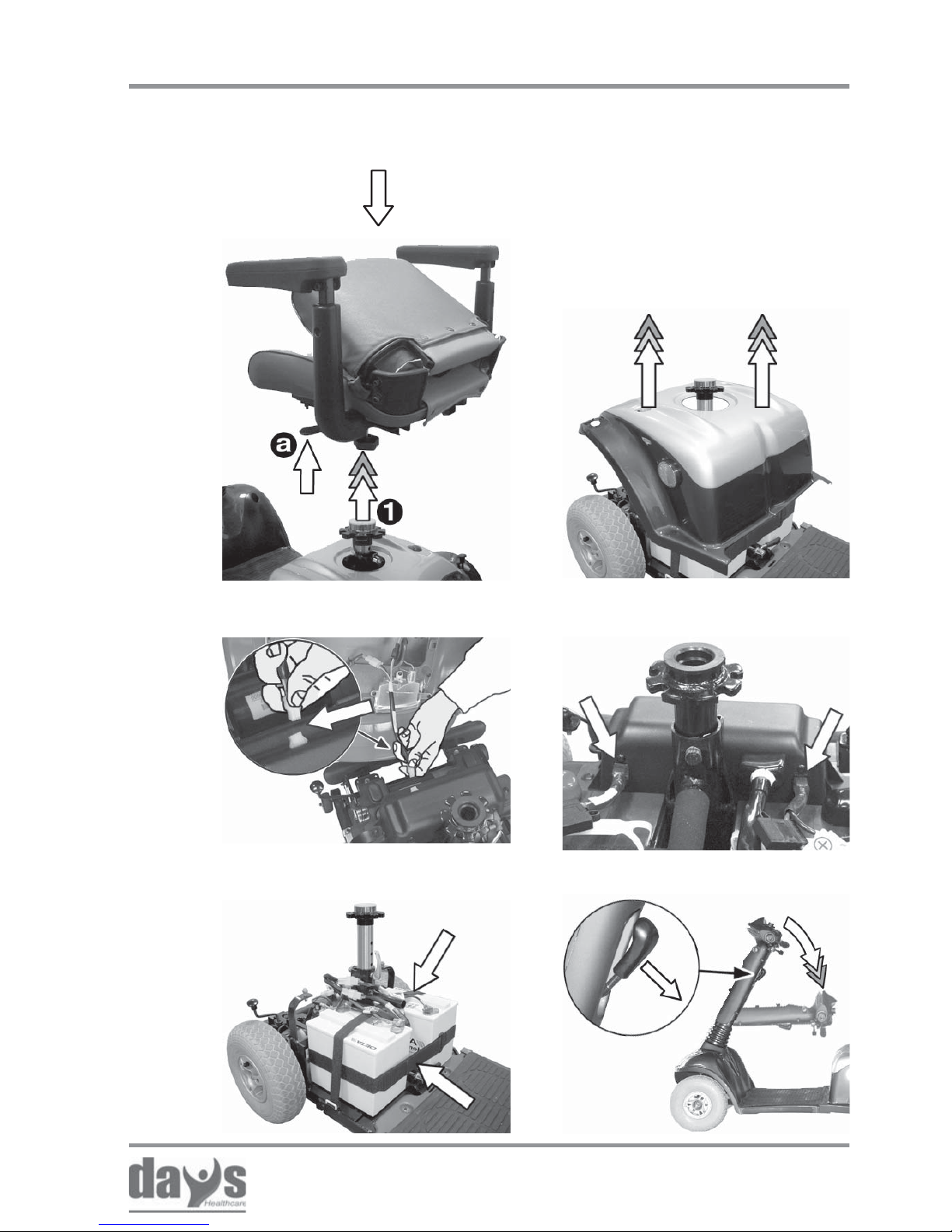
1.) Remove the seat
2.) Remove the rear panelling
3.) Remove the lighting cable
Dismantling the Strider (stages 1 to 10)
4.) Remove the battery plug
Brief instructions
18
Issued: 24.02.2005
STRIDER MD
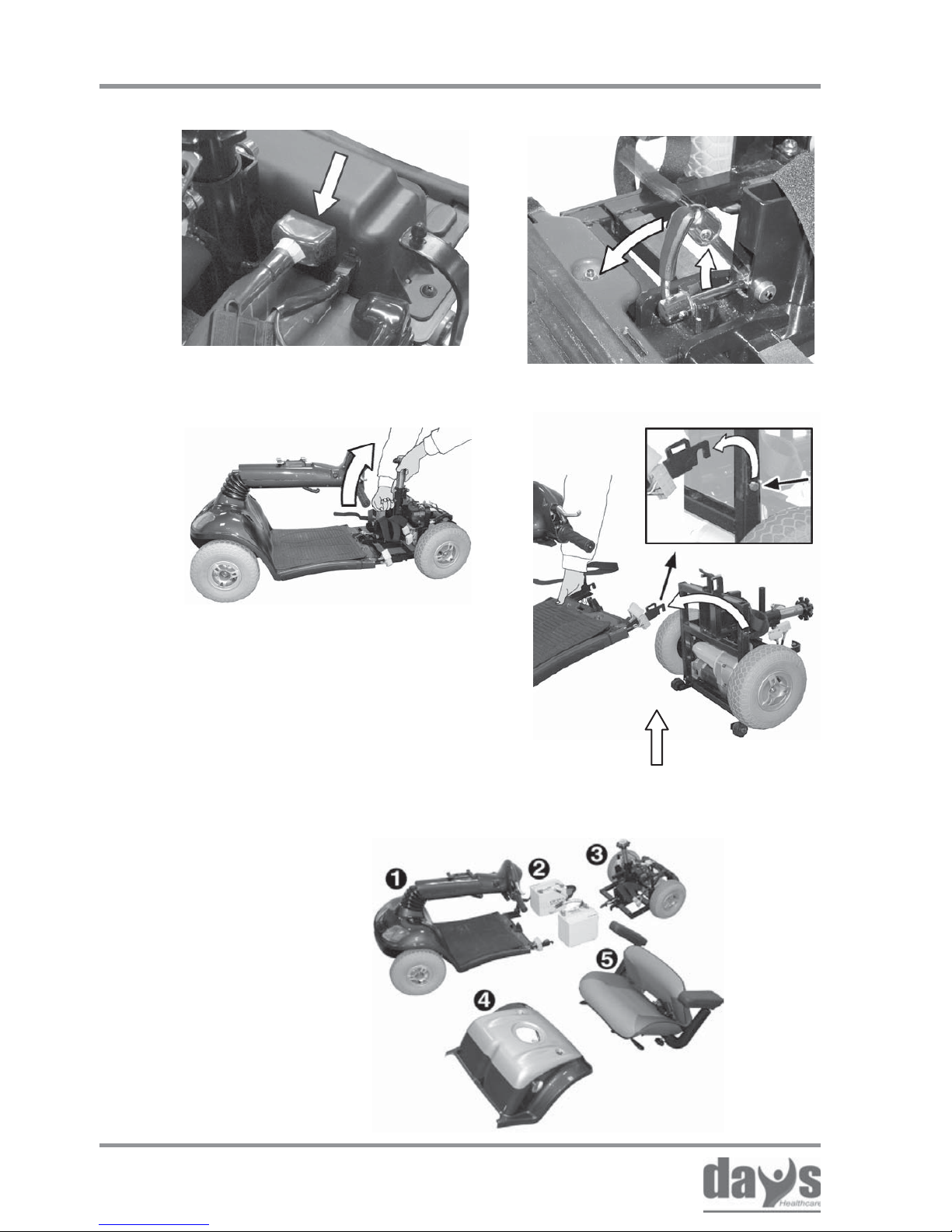
7.) Separate the front connector 8.) Un l ock the drive unit
9.) Tilt the drive unit away 10.) Remove the chassis
Reassembling the Strider
(Stages 10 to 1)
Brief instructions
The Strider dismantled:
1. Chassis
2. Batteries
3. Drive unit
4. Rear panelling
5. Seat unit
19
Issued: 24.02.2005
STRIDER MD
The following passage describes how to set up your Strider in order to
ensure that you hav e a comf ortable and saf e drive .
6. 0 Setting up the Strider
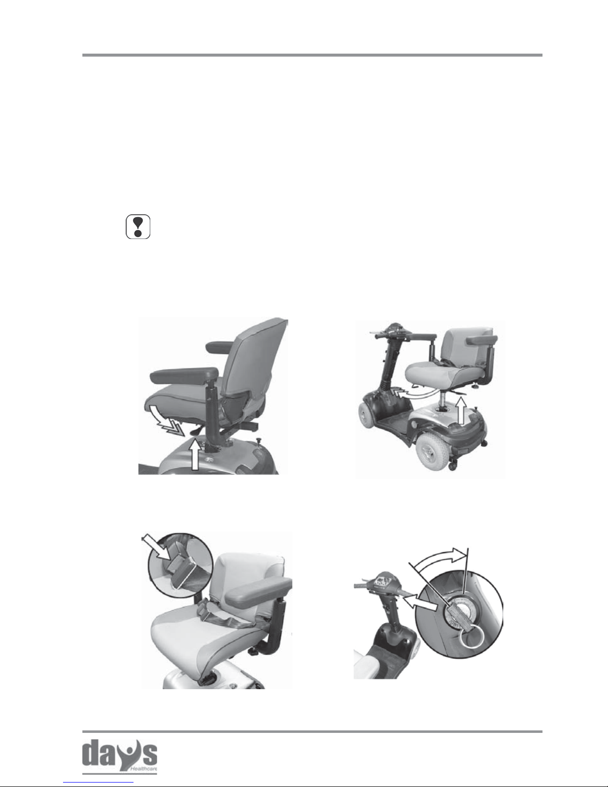
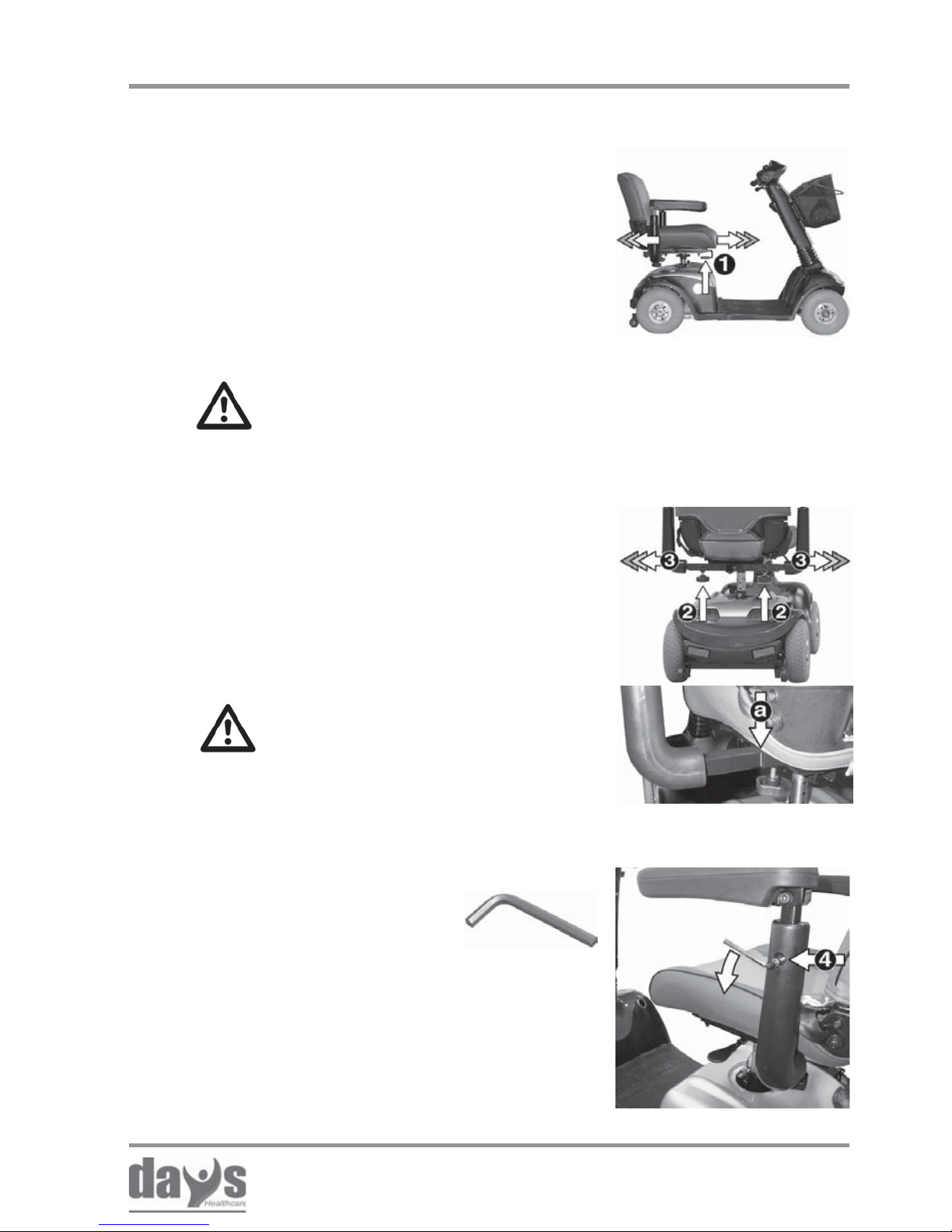
6.1 Adjusting the seat height
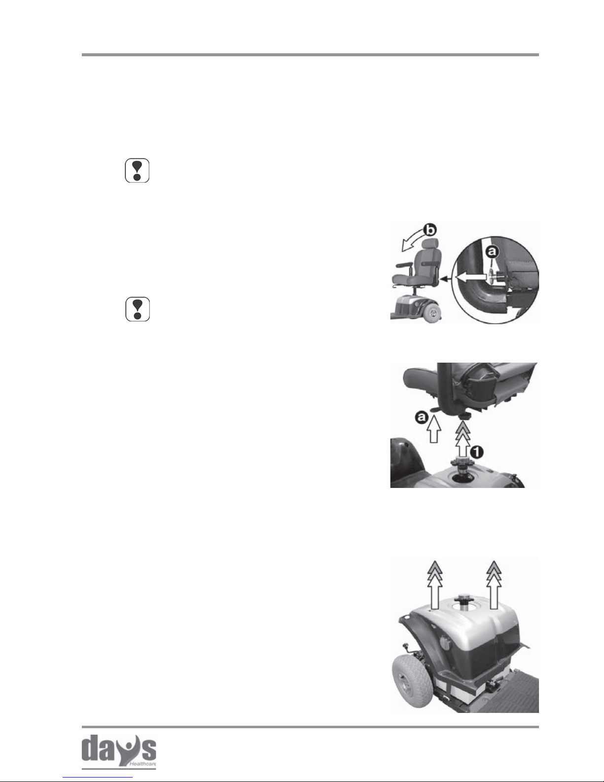
Tilt the backrest forwards.➨
NOTE!
The seat must be removed from the
Strider in order to adjust the seat height.
You should try to get help from a second
person if possible or contact your dealer .
Removing the seat
Removing the seat:
Lift the seat while pulling the seat lock
(a) out of the seat support (1).
➨
Adjusting the seat height
NOTE
If a captain’s seat is fitted, first pull
out the locking device (a) and then
fold the backrest forward (b).
Captain’ s seat
Pull the rear panelling off the Strider
upwards.
➨
Removing the rear
panelling
Removing the rear panelling:
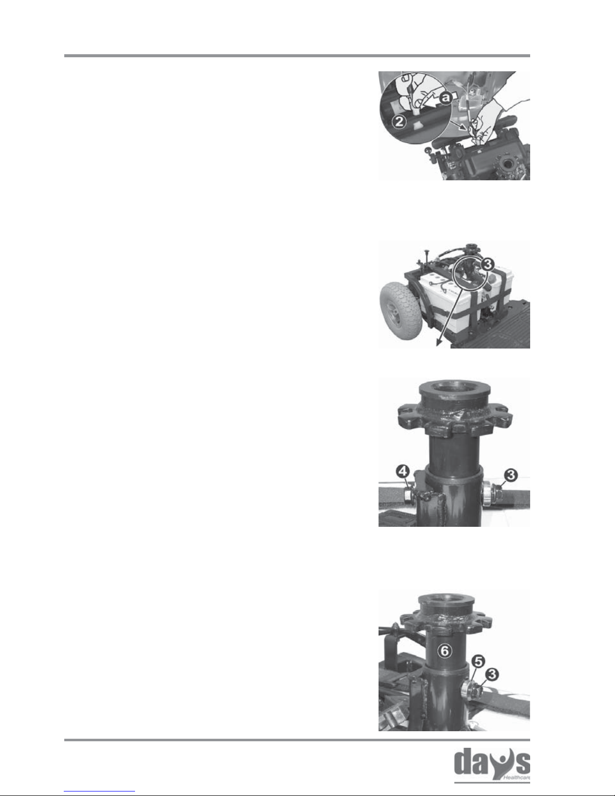
20
Issued: 24.02.2005
STRIDER MD
Adjusting the seat height
Pull the clamping bolt (3) with the form
shim (5) out of the seat support (6).
➨
Removing the clamping
bolt
Adjusting the seat height:
T ools required:
2 x ring spanner, size 12 mm
Hold the clamping bolt (3) with a ring
spanner (size 12 mm) and unscrew the
self-locking nut (4) with the other ring
spanner (size 12 mm).
➨
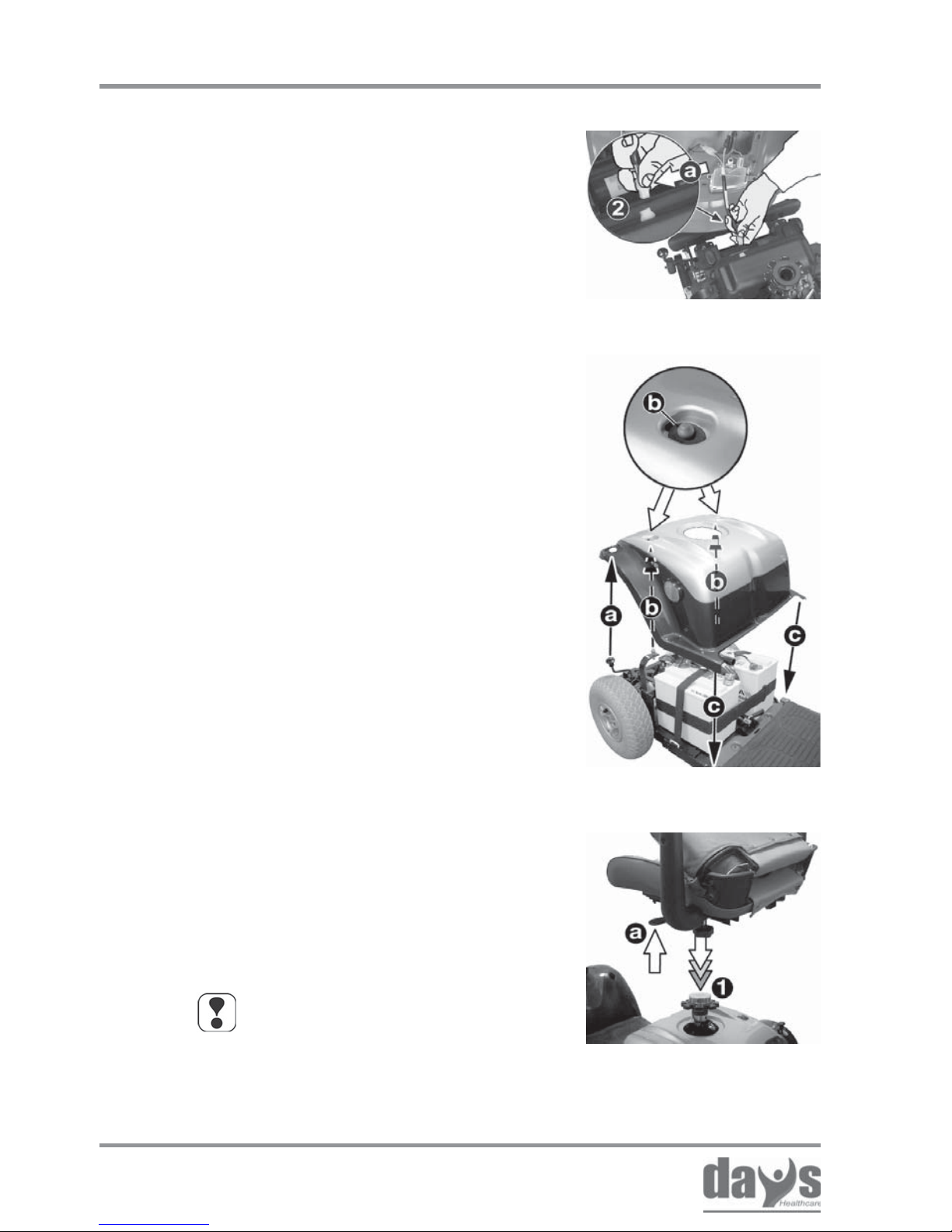
Remove the rear panelling.➨
Press the locking device (a) on the
plug and disconnect the electric cable
connecting plug (2) to the rear lights
and rear indicators.
➨
21
Issued: 24.02.2005
STRIDER MD
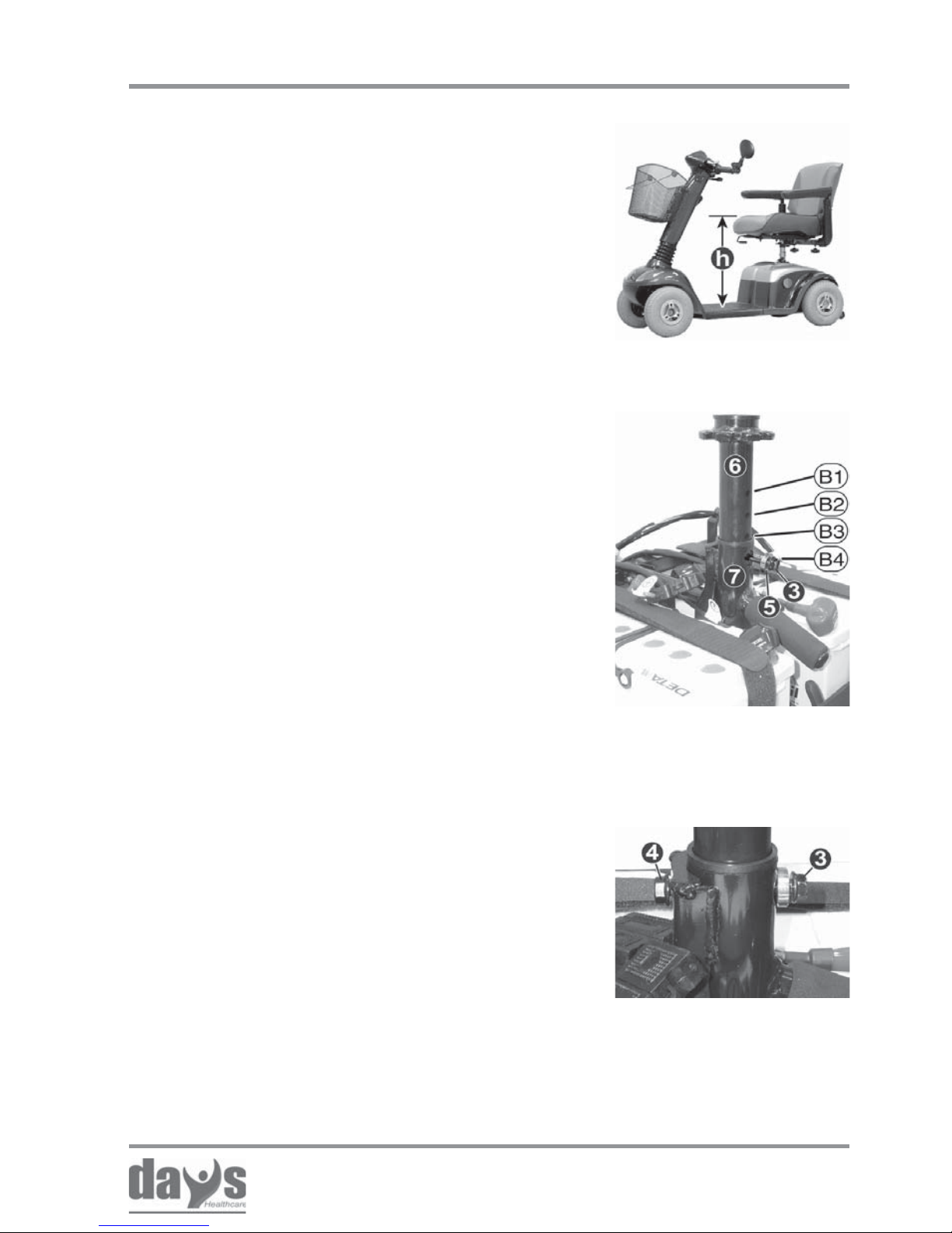
The seat height (h) is adjusted using the
four holes (B1 - B4) in the seat support.
Pull the seat support (6) out as far as
the required height until the correct
hole (B1-B4) appears in the seat tube
hole (7).
Push the clamping bolts (3) with the
form shim (5) into the seat tube from
the front.
➨
➨
Adjusting the seat
support
tighten the clamping
bolt
Screw the self-locking nut (4) and tighten
it (size 12 mm). While doing this, pre vent
the clamping bolt (3) from turning using a
second ring spanner (size 12 mm).
➨
Adjusting the seat height
22
Issued: 24.02.2005
STRIDER MD
Adjusting the seat height
Inserting the seat:
Inserting the seat
Pull the seat lock (a) and guide the seat
into the seat support (1) from above.
Let go off the seat lock and engage the
rotational adjustment by turning the seat
a little one way then the other.
➨
➨
NOT E
If after inserting the seat it is
not possible to turn the seat or
to pull the seatlock, the seat is
not properly locked.
Place the rear panelling onto the drive
unit from above.
While doing this:
- Introduce the engaging lever (a) into
the appropriate hole.
- Engage the rear panelling onto the
mountings (b) on the drive unit.
- Align the rear panelling to the
strider chassis (c).
➨
Plug in the light and indicator cable
connecting plug (2).
➨
Fixing the rear panelling
Fixing the rear panelling:
Connecting the light cable
23
Issued: 24.02.2005
STRIDER MD
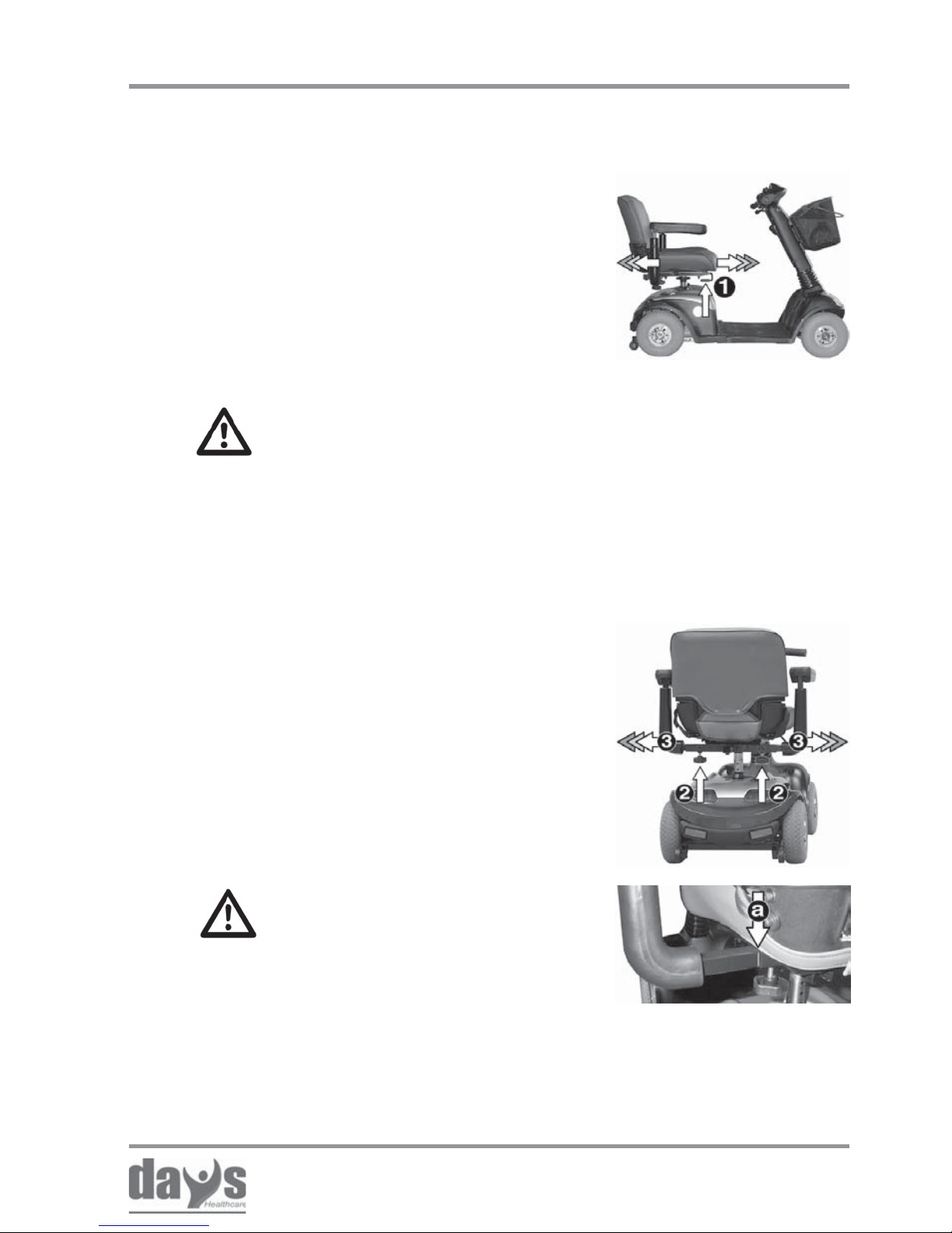
Loosen both clamping screws (2).
Pull both armrests (3) simultaneously to
the required width.
Secure the armrests by tightening the
clamping screws.
➨
➨
➨
Accident hazard due to
non-engaged seat!
• Ensure that the seat is properly
engaged after adjustment by
pushing the seat slightly forwards
and then backwards.
CAUTION!
• Do not pull the armrests further
out than the marking (a) for
maximum armrest width.
Moving the
seat
Adjusting the armrest
width
Pull the locking lever (1) upwards and
move the seat forwards or backwards to
the required distance.
Let go of locking lever and engage the
locking mechanism by pushing the seat
slightly forwards and backwards.
➨
➨
Adjusting the seat position
6.2 Adjusting the seat position - standard seat
6.2.1 Adjusting the distance between seat and
tiller
6.2.2 Adjusting the armrest width

24
Issued: 24.02.2005
STRIDER MD
T ools required:
1 x Allen key (size 5 mm)
Loosen the Allen screw (4) and remove.➨
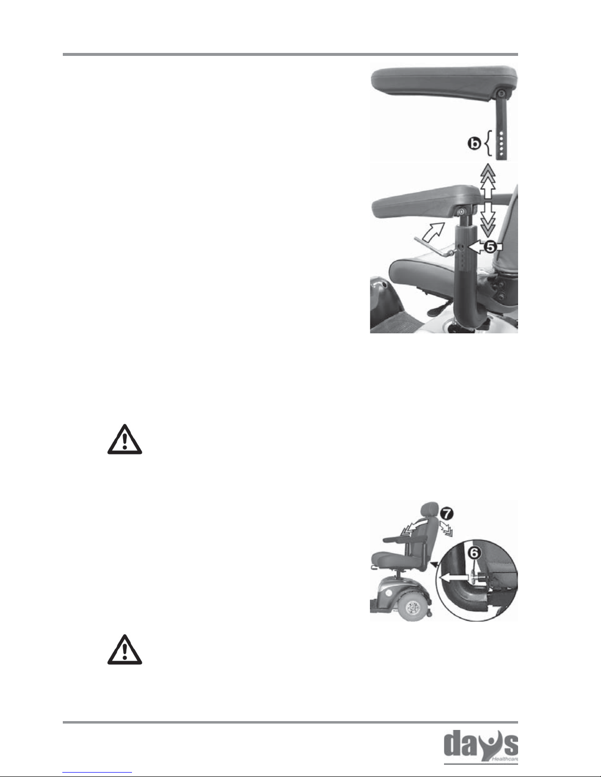
6.2.3 Adjusting the armrest height
The armrest height is adjusted using
four holes in the armrest support (b).
The height can be adjusted in stages
of 10 mm.
Pull the armrests upwards to the required
height until the hole in the armrest
support appears through the hole in the
seat tube (5).
Reinsert the Allen screw and tighten.
➨
➨
Loosening the fixing
Adjusting the armrest
height
Adjusting the seat position
25
Issued: 24.02.2005
STRIDER MD
T ools required:
1 x Allen key (size 5 mm)
Loosen the Allen screw (4) and remove.➨
6.3.3 Adjusting the armrest height Loosening the fixing
Loosen both clamping screws (2).
Pull both armrests (3) simultaneously to
the required width.
Secure the armrests by tightening the
clamping screws.
➨
➨
➨
CAUTION!
• Do not pull the armrests further
out than the marking (a) for
maximum armrest width.
Accident hazard due to non-engaged seat!
• Ensure that the seat is properly engaged after adjustment
by pushing the seat slightly forwards and then backwards.
Moving the
seat
Pull the locking lever (1) upwards and
move the seat forwards or backwards to
the required distance.
Let go of locking lever and engage the
locking mechanism by pushing the seat
slightly forwards and backwards.
➨
➨
Adjusting the seat position
6.3.2 Adjusting the armrest width
6.3.1 Adjusting the distance between seat and
tiller
6.3 Adjusting the seat position - captain´s seat
26
Issued: 24.02.2005
STRIDER MD
The armrest height is adjusted using
four holes in the armrest support (b).
The height can be adjusted in stages
of 10 mm.
Pull the armrests upwards to the required
height until the hole in the armrest
support appears through the hole in the
seat tube (5).
Reinsert the Allen screw and tighten.
➨
➨
Adjusting the
armrest height
Adjusting the seat position
6.3.4 Adjusting the backrest inclination
The backrest inclination can be adjusted in
three locking stages.
1st stage = drive setting
2nd stage = drive setting
3rd stage = not for driving!
Adjusting the backrest
Tipping hazard!
• Only adjust the seat adjustment to the third
position when the vehicle is not travelling!
Pull the locking lever (6) and move the
backrest forwards or backwards to the
required position (7).
Let go of the locking lever and engage
the locking mechanism by pushing the
backrest slightly forwards and
backwards.
➨
➨
Accident hazard if backrest is not
properly engaged!
• Ensure that the backrest is properly engaged
after adjustment by pushing it slightly forwards
and then backwards.
27
Issued: 24.02.2005
STRIDER MD
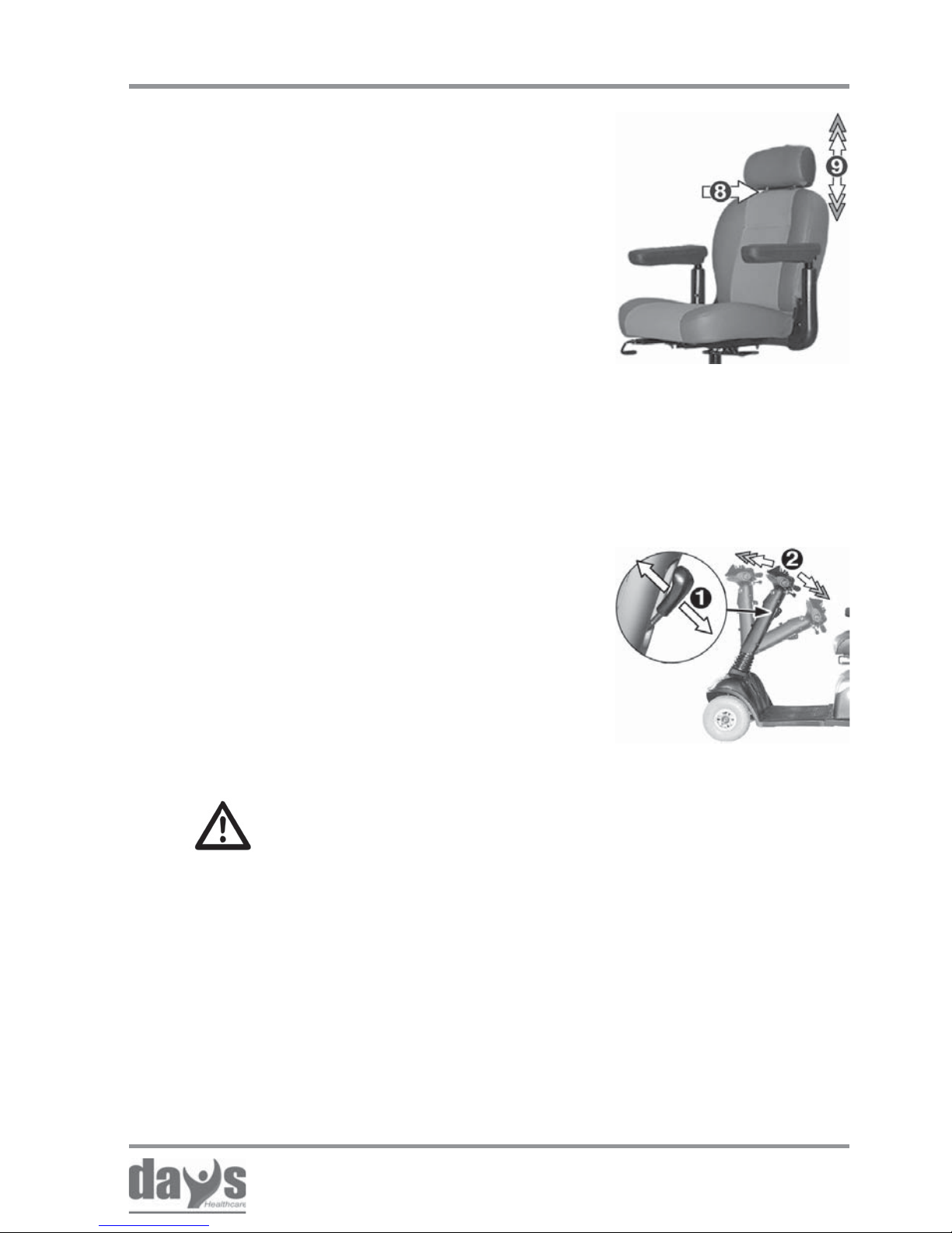
Always adjust the tiller so that you can
reach all displays and controls easily at any
time. The tiller can be v ariably adjusted.
Push or pull the locking lever (1).
Push the tiller forwards or backwards
into the required position.
Release the locking lev er .
Ensure that the tiller is engaged correctly
by moving it backwards and forwards.
➨
➨
➨
➨
Accident hazard due to
non-engaged tiller!
• Ensure that the tiller is properly
engaged after adjustment by
pushing it slightly forwards and
then backwards.
adjusting the tiller
Adjusting the seat position
Adjusting the
headrest
6.3.5 Adjusting the headrest hight
6.4 Adjusting the tiller angle
Press the locking device (8) and push
the headrest upwards or downwards into
the required position (9).
➨
28
Issued: 24.02.2005
STRIDER MD
Driving information
7.0 Information about safe Strider driving
Always carry out the safety information
described in chapter 1.5 “Safety during driving“!
Driving the Strider is very simple and after a few practice sessions you
will find it very easy.
The following information should help you to drive safely through traffic:
• always match your speed to the driving situation in which you find
yourself.
• always reduce the speed when you are driving through:
- unclear areas
- narrow gaps
- tight curves
- inclines
- ramps
• take a trial run with the Strider in an area with no pedestrians,
or in a closed-off area
• always steer the Strider using both hands on the handlebars
• always keep your feet in the foot area while driving the Strider
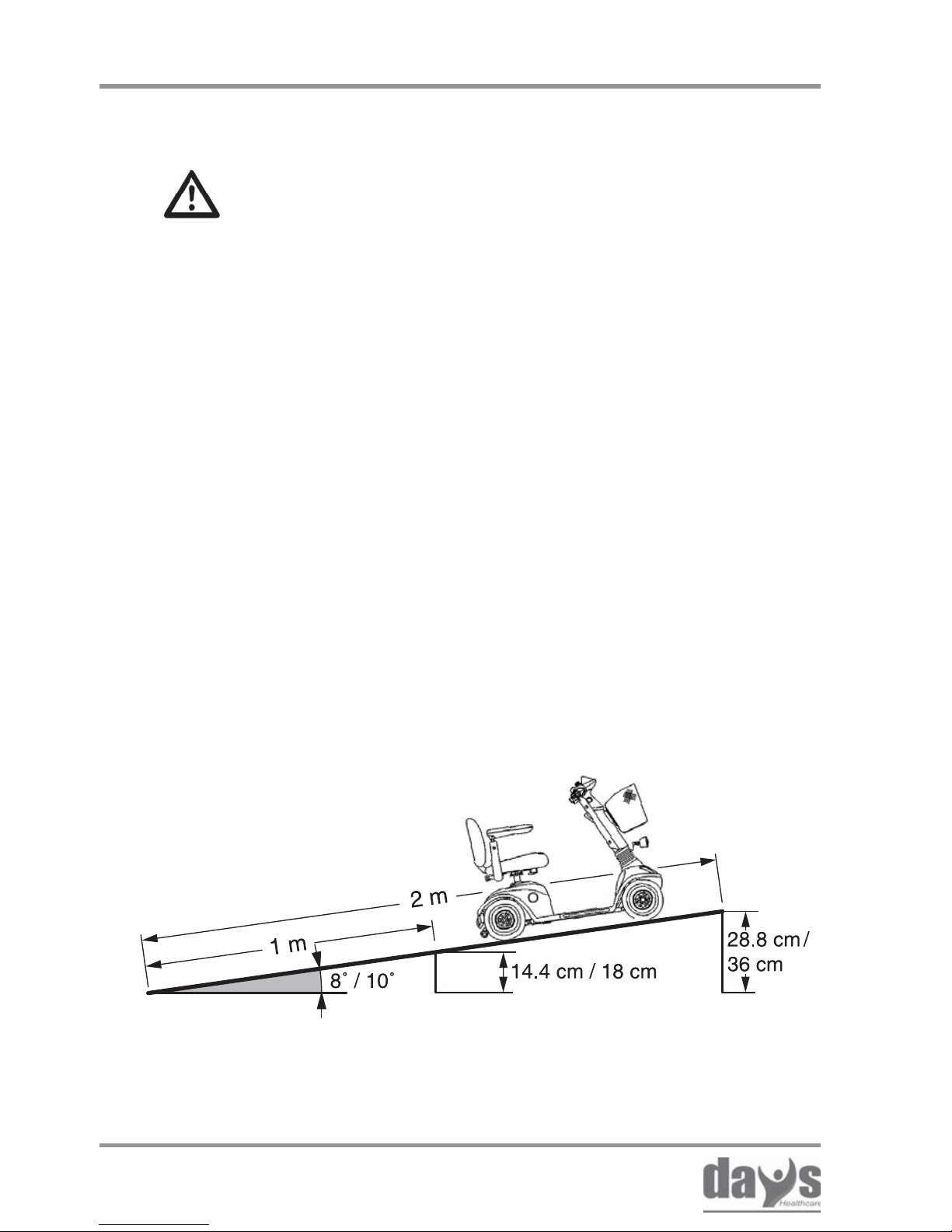
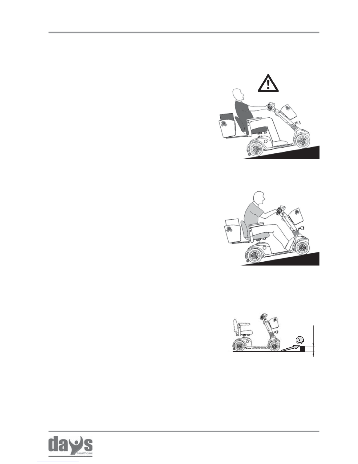
7.1 Driving up inclines and down slopes
Climb angle examples:
a 1 metre long ramp should not be higher than 14.4 cm (MD 3) /
18 cm (MD 4)
a 2 metre long ramp should not be higher than 28.8 cm (MD 3) /
36 cm (MD 4)
The Strider can climb up
inclines of up to 8° (MD 3) or
10° (MD 4) without danger .
29
Issued: 24.02.2005
STRIDER MD
8 cm
7.2 Overcoming obstacles
The Strider can climb over obstacles such
as kerbstones up to height of 8 cm without
any problem.
Driving information
You can achieve increased tipping saf ety if:
• you adjust the seat in a more forward
position.
• you adjust the backrest (captain’ s seat)
to be vertical
• you lean your upper body slightly forwards
(see sketch)
There is an increased danger of tipping
when climbing or descending gradients if:
• the Strider is loaded at the back and
additionally
• the backrest (captain’s seat) is leant
towards the back and
• the seat has been adjusted to its rear
position.
Increased
tipping safety
Tipping
hazard!
• Avoid driving across an incline
(always try to drive in the direction
of the incline / decline).
 Loading...