

Page 1
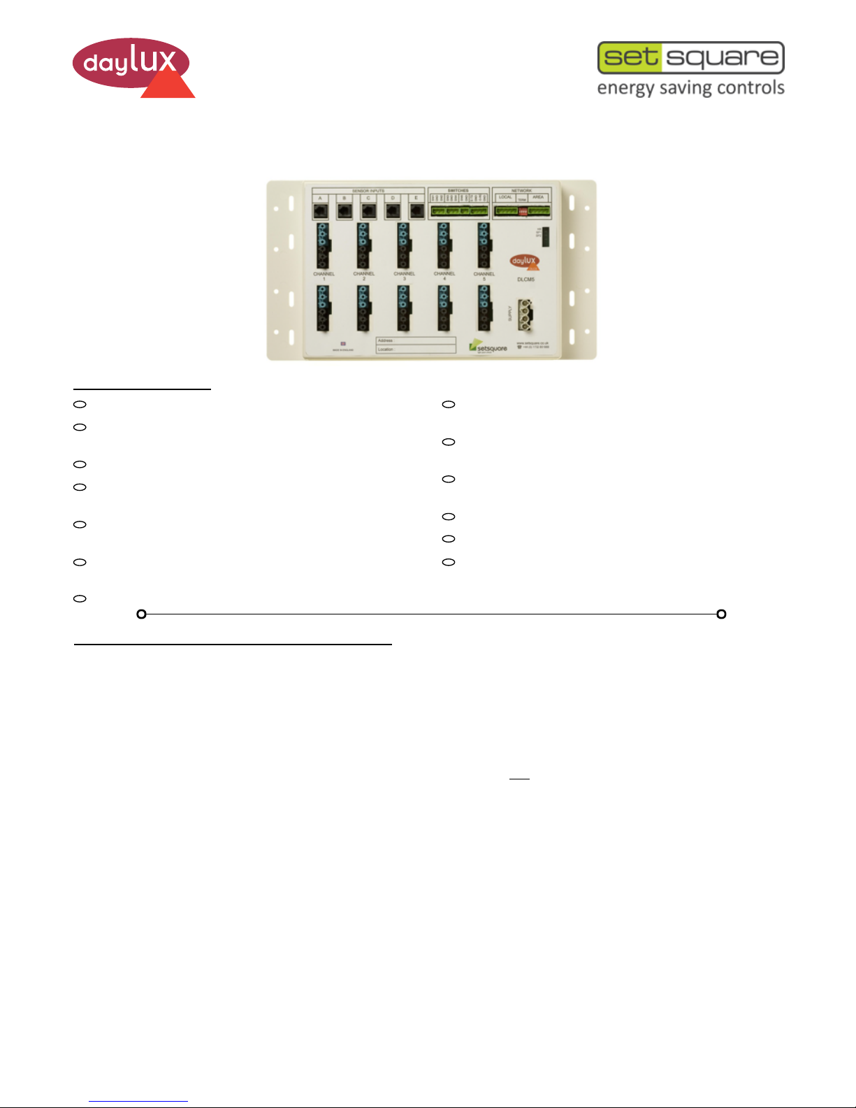
DLCS
SET-DLCM3,5 (A,D)
10 WAY PLUGGABLE LIGHTING CONTROL MODULE
1 of 4
PRODUCT FEATURES
BASIC USER GUIDE
SELF CONFIGURATION AND FACTORY DEFAULTS
The SET-DLCM 3 or 5 run through a unique, automatic, simply
intelligent self-configuration process once powered up. This allows a
system to be fully functional ‘out of the box’ without the need for initial
setup and programming. The self-configuration process is activated
every time the DLCM is powered up, until it has been either programmed
or settings have been changed/modified and stored.
How a system self configures is dependant on various factors.
Such as:-
Whether the SET-DLCM is either a 3 or 5 channel lighting control
module. If occupancy sensors are attached, how many and which input
port they are plugged into.
If light level sensors are attached, how many and which input port they
are plugged into.
If SET-DFP type faceplates are attached.
If more than one SET-DLCM or other ‘Output’ devices are networked
together.
The self configuration process is dependant on a set of preprogrammed
‘Factory Defaults’. These defaults are as follows:-
Occupancy Delay: The SET-DLCM will switch its output channels off
after occupancy ceases. Time delay is 10 minutes by default.
Dimming Protocols: SET-DLCM3-D and SET-DLCM5-D outputs are
DSI (default). SET-DLCM3-A and SET-DLCM5-A outputs are 1-10v
Analogue.
Dimming Channels: Configure depending on which sensor inputs
light level sensors are plugged into. (See ‘Channel Self -Configuration
Table on page 3).
Network Control: When multiple ‘Output’ devices are networked
(connected) together, how they configure will be dependant on
whether each output device has its own sensors or not. If sensors are
connected to only one output device ALL other output devices on that
network will mirror the output device with the sensors directly
connected to it. If sensor(s) are connected to multiple output devices,
then ALL output devices will operate independently for occupancy
and light level.
Please note: ALL commands and triggers from faceplates or switches
are broadcast across the network and ALL output devices will
respond.
3 or 5 Channel control and lighting distribution.
10 x Outputs to luminaries using industry standard
‘Wieland’ connectors.
Capable of Dimming and / or Switching from one unit.
All common dimming protocols supported (DSI, DALI
‘Broadcast’ and 1-10v Analogue).
Automatic light level dimming or switching (daylight linking).
Maintains a specific Lux level and saves energy.
Manual dimming or switching - via faceplates or momentary
switches for scene selection, off, raise and lower.
Presence and / or absence detection.
Unique automatic, simply intelligent self-configuration detects sensors and configures itself accordingly.
Programmable - allows the flexibility of re-configuration for
any future changes to the controlled area’s use.
Standalone or multiple, fully networked systems using
RS485 networking. Fully scalable.
Override facility.
Emergency Lighting test facility.
Easy integration with BMS (Building Management) and AV
(Audio/Visual) systems.
Presence/Absence: The SET-DLCM’s can operate as either a presence
or absence detection system. In presence detection mode the lighting
will automatically switch on when someone enters an area where there
are occupancy detectors. In absence mode the lighting will only switch
on when someone operates a switch or scene button on a faceplate. The
lighting can also be manually turned off by the same switch or by the
‘Off’ button on a faceplate. By default, presence mode is set to ‘On’.
Scenes: When a faceplate is on a system, scenes can be selected
by operating a ‘Scene’ button on the faceplate. If a light level sensor
is also on the system, the default ‘Scenes’ will be as follows:-
Scene 1 = Automatic (Daylight linked). Output Level = High
Scene 2 = Automatic (Daylight linked). Output Level = Low
Scene 3 = Manual (Fixed Output). Output Level = High
Scene 4 = Manual (Fixed Output). Output Level = Low
If a faceplate is fitted without any light level sensors, then Scene 1 &
2 are as per scenes 3 & 4 above.
Manually Changing Light Levels: It is possible to manually adjust
light levels temporarily for your convenience by using the ‘Raise’ or
Page 2
2 of 4
‘Lower’ functions either on a faceplate and/or a switch on input 1. Once
the system has been allowed to ‘time out’, light level will revert to the
default light level setting as above.
SWITCH INPUTS - OPERATION & DEFAULTS
The SET-DLCM3 and SET-DLCM5 have 5 x switch inputs which can be
used for various manual control options. There are also specific inputs
for ‘Emergency Test’ and ‘Override’. See ‘Inputs/Outputs And Status
LED’s’ on page 3 and the ‘Switch Functions Table’ below for further
details.
Switch 1: By default, this switch input is programmed to operate as ‘On’,
‘Off’, ‘Raise’ and ‘Lower’ using a momentary push switch.
Switch 2: Test Mode. A momentary switch wired to this input can be
used to activate ‘Test Mode’. The switch can be used to toggle between
on and off. With test mode on, the system will time out after occupancy
has ceased and switch lighting off after 10 seconds. A secondary
function of this switch is to allow you to invoke a ‘System Reboot’. Press
and hold the switch for more than 5 seconds then release. The device
will restart without losing any previously programmed settings.
Switch 3: Programming Mode. A momentary switch wired to this input
will allow some quick and simple programming options to be selected. A
short press on this switch will toggle between DSI & DALI dimming
modes. A long press will store the currently selected scene’s output to
memory. Set your desired lighting output level by using the raise/lower
buttons on a faceplate or a switch wired to switch input 1. Store this level
with a long press on switch 3.
Another function of this switch is to enable a quick method of invoking a
‘Factory Reset’. Press and hold the switch for more than 5 seconds then
release. The device will reboot with all previously programmed settings
being cleared from memory.
Switch 4 & 5:
These switch inputs are not programmed on leaving the factory for any
particular function and can be programmed as required.
Switch 6: Emergency Test (E-TS): Input for standard ‘Keyswitches’ to
allow emergency lighting to be tested. By default the normal lighting will
turn off whilst discharging the emergency lighting. (Can be programmed
to keep the normal lighting on whilst discharging the emergency lighting)
This function affects all ‘Output’ devices on the same network.
Switch 7: Override (O-RD): By default this input is programmed to allow
for a complete system override either from a switch or volt-free contact.
On operation, the lights will go to full output with all inputs from any input
devices or sensors being ignored. May be used for interfacing with alarm
or BMS systems etc.
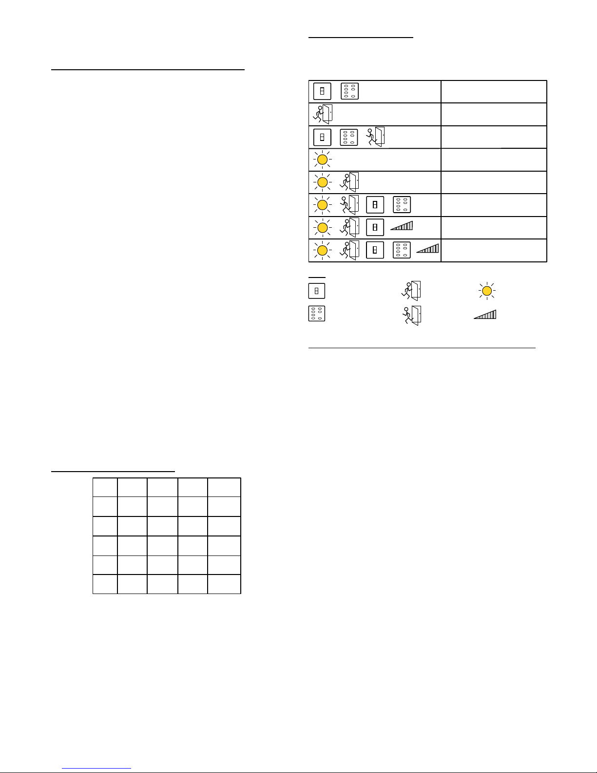
MODES OF OPERATION
The following table describes some basic ‘Modes Of Operation’
based on types of input, such as occupancy sensors, light level
sensors, switches and faceplates.
All methods connect to the RS485 network, either by direct connection at a specific device or through a SET-DPP (Daylux Programming
Port). The SET-DHPP also has the ability to use an IR (Infra-Red)
Link as a means of connecting to the network. Please see the
‘SET-DPP User Guide’, the ‘SET-DFP User Guide’, the ‘SET-DHHP
User Guide’ and the ‘SET-DPCS User Guide’ for further information
and programming instructions. Please contact Setsquare for any
programming requirements. (Contact details on back page).
Once the systems have been commissioned, the default settings
most likely would have been changed to specific requirements for the
site. If Setsquare undertake the commissioning, these settings are
recorded in an engineer’s report which is issued in the handover
documentation for the project.
CHANGING DEFAULTS SETTINGS - PROGRAMMING
The SET-DLCM is part of the DLCS range of products which are fully
networkable and programmable. It is possible to change any of the
default settings (program) for time delay, automatic light level,
dimming protocol change between DSI and DALI (SET-DLCM3-D
& SET-DLCM5-D only), manual scene levels and associated channel
selection, occupancy inputs and associated channels, switch input
configuration, network commands (such as corridor hold, group
control and interaction between devices).
There are various methods which can be used to program the
SET-DLCM. These are:- SET-DFP (faceplates), a SET-DHHP
(Daylux Hand Held Programmer) and the SET-DPCS (Daylux PC
Software).
The method used will determine what level of programming can be
achieved. The SET-DFP is the most basic means of programming
and the SET-DPCS is the most advanced.
MIN
MAX
MANUAL (ON OFF)
PRESENCE
ABSENCE
DAYLIGHT
DAYLIGHT / PRESENCE
DAYLIGHT / ABSENCE
DAYLIGHT / PRESENCE / DIMMING
DAYLIGHT / PRESENCE / SCENES /
DIMMING
MIN
MAX
KEY:
Daylight Link
Switch
Absence
Dimming
Scenes / Faceplate
Presence
MIN
MAX
Notes: A ‘short press’ is less than half a second. ‘Press and hold’ is for
longer than half a second. *Raise and Lower will only function when
dimmable lighting is being controlled.
SWITCH FUNCTIONS TABLE
SHORT
PRESS
SW1
SW2
SW3
SW7
LIGHTS
ON
LIGHTS
OFF
SHORT
PRESS
PRESS
HOLD
PRESS
HOLD
INCREASE
LEVEL*
DECREASE
LEVEL*
TEST
ON
TEST
OFF
OVERRIDE
ON
OVERRIDE
OFF
SW6
EM TEST
ON
EM TEST
OFF
For >5s
RESTART
DSI/DALI
TOGGLE
>0.5s
STORE
SCENE
>5s
FACTORY
DEFAULTS
Page 3

3 of 4
Sensor Inputs and Channel Outputs.
Sensors will control the desired output channels through unique, automatic self-configuration on light level according to the table above.
Movement detection is ‘linked’ across all channels by default (This feature is re-programmable).
CHANNEL SELF CONFIGURATION TABLE.
CH A
LIGHT LEVEL SENSOR INPUTS
CH B CH C SET-DLCM5
OUTPUT CHANNELS
ü
ü
ü
ü
ü
ü
ü
CH D CH E
1 2 3 4 5
1 2 3 4 5
1 2 3 4 5
1 2 3 4 5
1 2 3 4 5
1 2 3 4 5
1 2 3 4 5
1 2 3 4 5
ü
ü
ü
ü
ü
ü
ü
ü
ü
ü
ü
ü
ü
ü
1 2 3
SET-DLCM3
1 2 3
1 2 3
1 2 3
Lighting Outputs.
The SET-DLCM3 has 4 x outputs for channel 1, 4 x for channel 2 and 2 for channel 3. The SET-DLCM5 has 2 x outputs per channel.
DLCS
NETWORK
AREA
TERM
SET-DLCM3
HB
SP1
SP2
www.setsquare.com
+44 (0) 1732 851888
F
CHANNEL
3
SW2
SW3
GND
SW4
SW5
GND
E-TS
GND
O-RD
GND
SWITCHES
LOCAL
SUPPLY
SW1
GND
CHANNEL
2
E
CHANNEL
1
SENSOR INP UTS
C D
MADE IN ENGLAND
BA
Address:
Location:
ON
1
4
SET-DLCM3 - 3 Channel Unit Shown
STATUS LED’s
HB, SP1 & SP2
RS485 NETWORKS
Local and Area
SWITCH INPUTS
1 to 5 + Emergency Test
and Override
SENSOR INPUTS
A to E
OUTPUT CHANNELS
1 to 3 (SET-DLCM3)
MAINS SUPPLY
INPUT
INPUTS/OUTPUTS & STATUS LED’s.
Page 4

4 of 4
01920 462121
01920 466881
sales@modelighting.com
www.setsquare.com
SET-DLCM3-5 - Basic User Guide 19/04/2016
DS329-V1.0
MADE IN
ENGLAND
Setsquare Energy Saving Controls
The Maltings
63 High Street
Ware
Hertfordshire
SG12 9AD
United Kingdom
These LED’s, (HB = Yellow), (PSU’s = Green) which can be seen from
the front of the SET-DLCM, will give an indication of the current status
of the unit.
The ‘HB’ LED will flash at different rates to indicate the current status of
the system and the ‘SP1 & SP2’ LED’s will be either on or off to indicate
the internal power supply status. See ‘Inputs/Outputs & Status LED’s’ on
page 3 for their location and the ‘LED Status Tables’ opposite for further
information.
In the event that the PSU LED’s indicate a ‘Power Fault’ or ‘No Power’
status, please contact Setsquare for advice. See below for contact
details.
SP1 SP2 STATUS
POWER
GOOD
POWER
FAULT
POWER
FAULT
NO
POWER
STATUS LED’s - HEARTBEAT (HB) & POWER SUPPLIES
(SP1 and SP2)
LED STATUS TABLES
NOTES:
GLOSSARY OF TERMS.
Output Device - Lighting control module which can switch lighting
on/off/dim such as the SET-DLCM3,5 or SET-DDC1,2,4.
Input Device - SET-DFP (Faceplate), Occupancy Sensor, Light Level
Sensor, Remote Control IR Receiver, Switch.
Channel - A single output or group of outputs that are controlled
together.
Group - Multiple output channels, which can be on different ‘Output’
devices which are controlled together.
Scene - The output level of one or more channels at any given time
which is activated by the same input, such as a button on a faceplate or
switch.
Network - Carries communication data between devices connected to it.
Addressable - Each device connected to a network has a unique
address which enables communication directly to that device.
LED - Light Emitting Diode.
PSU - Power Supply Unit.
Daylight Linking - Ambient light level (Lux) is monitored by the means
of a sensor. If the Lux level is above a preset level, lighting output will be
decreased to save energy and to maintain a constant level in the
working area. When the ambient light level falls below the preset level,
the lighting output will be increased to maintain the desired level.
On non-dimmable lighting the lights can be switched off and on
according to a preset level.
Dimming Protocols - DSI, DALI, 1-10v Analogue. Low voltage lighting
interface which allows lighting to be controlled/regulated to a different
level other than maximum output. With DSI and DALI, it is also possible
to turn lighting off through this interface.
Presence Detection - (Fully Automatic). Upon entry to an area with
presence detection, the lighting will switch on automatically through
occupancy sensors and remain on all the time the area is occupied.
Once the area is vacated, the lighting will turn off automatically after
a preset time delay.
Absence Detection - (Semi-Automatic). Lighting in an area which
has absence detection has to be initially switched on manually upon
entry. After this, the occupancy sensors in the area will keep the
lighting on whilst the area is occupied. When the area is vacated, the
lighting will turn off automatically after a preset time delay. Lighting
can also be turned off by operating a momentary switch or the ‘Off’
button on a faceplate as applicable.
STATUS
HB
SLOW
MED
FAST
SELF
CONFIGURATION
DECREASING
LIGHT LEVEL
NORMAL
OPERATION
INCREASING
LIGHT LEVEL
ON
 Loading...