

Page 1
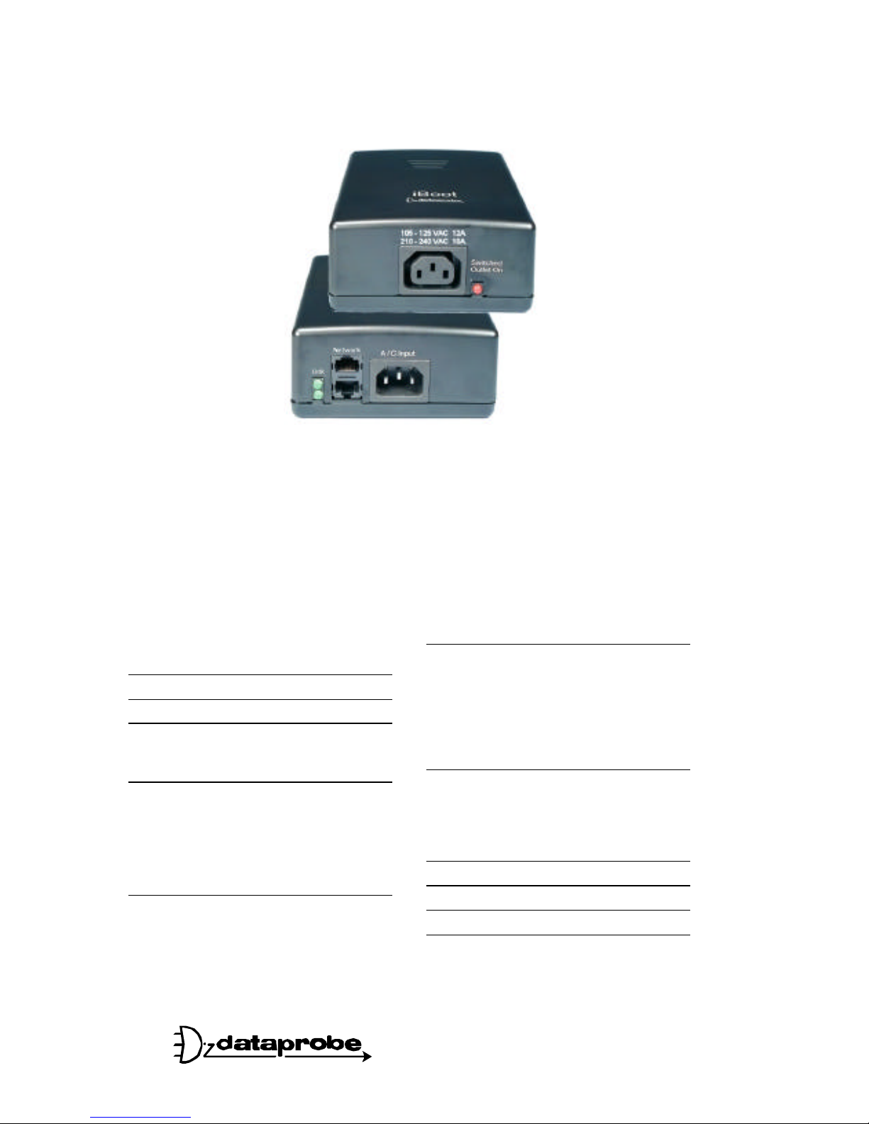
iBoot
Web Enabled Remote Power Control
Table of Contents
Important Safety Information 2
General Description 3
Hardware Installation 5
Ethernet Connections
A/C Power Connections
iBoot Configuration 8
Setting IP Address
Using DHCP
Using Web Browser Access
Using ibootrst.exe
Using ARP / Ping
Web Browser Operation 11
Password Protection
Control & Status Page
iBoot Setup
13
Device Settings
TCP/IP Settings
Auto-Ping
Heartbeat
Passwords
Forgotten Password
Advanced Operation 16
Auto Ping
Heartbeat Monitor
Control Programs
Direct TCP Control
Specifications 22
User Settings 22
Tech Support & Warranty 23
More Power Control Solutions 24
Ver: 2.0 and up
11 Park Place / Paramus, NJ 07652
201-967-9300 www.dataprobe.com
Page 2

Ver 2.0 and up iBoot Page 2
IMPORTANT SAFETY INSTRUCTIONS
When using this product, basic safety precautions should always be followed
to reduce the risk of fire, electric shock, and injury to persons, including the
following:
1. Read and understand all instructions.
2. Follow all warnings and marked on the product.
3. Unplug this product from the wall outlet before cleaning. Do not use liquid cleaners or aerosol
cleaners. Use a damp cloth for cleaning.
4. Do not use this product in an outdoor environment or near water, for example, near a bath tub, wash
bowl, kitchen sink, or laundry tub, in a wet basement, or near a swimming pool.
5. Do not place this product on an unstable cart, stand, or table. The product may fall, causing serious
damage to the product.
6. Slots and openings in this product and the back or bottom are provided for ventilation to protect it
from overheating; these openings must not be blocked or covered. The openings should never be
blocked by placing the product on the bed, sofa, rug, or other similar surface. This product should
never be placed near or over a radiator or heat register. This product should not be placed in a builtin installation unless proper ventilation is provided.
7. This product should be operated only from the type of power source indicated on the marking label. If
you are not sure of the type of power supply to your home, consult your dealer or local power
company.
8. This product is equipped with a three wire grounding type plug, a plug having a third (grounding) pin.
This plug will only fit into a grounding type power outlet. This is a safety feature. If you are unable to
insert the plug into the outlet, contact your electrician to replace your obsolete outlet. Do not defeat
the safety purpose of the grounding type plug. Do not use a 3-to-2 prong adapter at the receptacle;
use of this type adapter may result in risk of electrical shock and/or damage to this product.
9. Do not allow anything to rest on the power cord. Do not locate this product where the cord will be
abused by persons walking on it.
10. Do not overload wall outlets and extension cords as this can result in the risk of fire or electric shock.
11. Never push objects of any kind into this product through slots as they may touch dangerous voltage
points or short out parts that could result in a risk of fire or electrical shock. Never spill liquid of any
kind on the product.
12. To reduce the risk of electrical shock, do not disassemble this product, but take it to a qualified
serviceman when some service or repair work is required. Opening or removing covers may expose
you to dangerous voltages or other risks. Incorrect re-assembly can cause electric shock when the
appliance is subsequently used.
13. Unplug this product from the wall outlet and refer servicing to qualified service personnel under the
following conditions:
a) When the power supply cord or plug is damaged or frayed.
b) If liquid has been spilled into the product.
c) If the product has been exposed to rain or water.
d) If the product does not operate normally by following the operating instructions. Adjust only
those controls that are covered by the operating instructions because improper adjustment of
other controls may result in damage and will often require extensive work by a qualified
technician to restore the product to normal operation.
e) If the product has been dropped or has been damaged.
f) If the product exhibits a distinct change in performance.
14. Avoid using a telephone (other than a cordless type) during an electrical storm. There may be a
remote risk of electric shock from lightning.
15. Do not use the telephone to report a gas leak in the vicinity of the leak.
16. Do not exceed the maximum output rating of the auxiliary power receptacle.
SAVE THESE INSTRUCTIONS
Page 3
Ver 2.0 and up iBoot Page 3
General Description
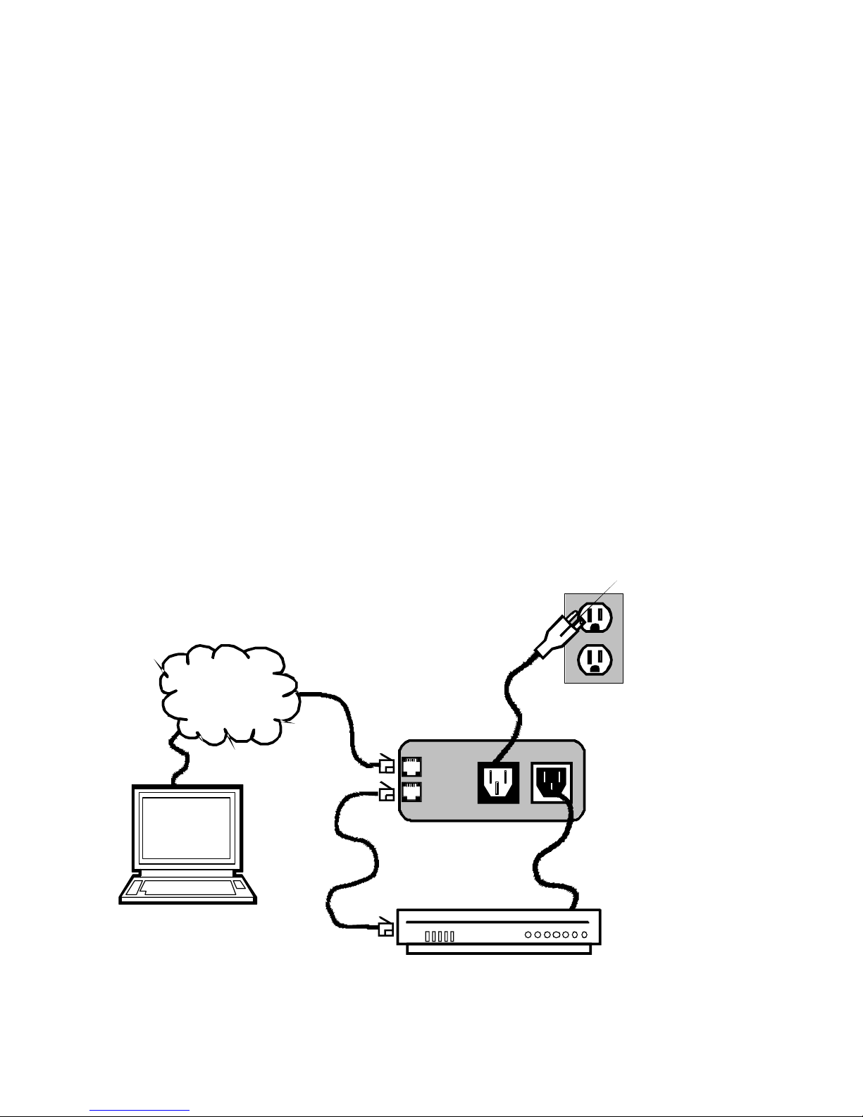
The iBoot is a network attached, IP addressed, Web Controlled AC power
switch. Anyone with a web browser can access iBoot to perform power On,
Off or Power Cycle (Reboot or Power Burst). iBoot is password protected for
security.
iBoot features international standard IEC320 connections and is compatible
with power mains worldwide. Dual Ethernet jacks with built-in hub make
installation of iBoot easy.
Uses for iBoot:
♦ Remote reboot of any device, routers, servers, kiosks, etc. The device to
be rebooted need not be network attached.
♦ Secure sensitive devices by keeping them powered off when not in use.
This prevents hackers from seeing them at all times.
♦ Power down equipment when not needed for power savings and to save
on wear and tear.
♦ Power up alert devices like sirens, lamps, messages; or control
environmental system like heaters, coolers pumps, etc.
Pwr Out
PC with
Web Browser
Inter- or
Intra- Net
Dual
10/100
Ethernet
Pwr In
iBoot
Web Controlled
Power Switch
Page 4

Ver 2.0 and up iBoot Page 4
Multiple Control Options
In addition to the Web control capabilities, iBoot features several other
means to operate automatically or under computer control. Each of these
methods is detailed in the Advanced Operation section on page 16.
Auto-Ping: The Auto-Ping feature allows iBoot to automatically detect failed
equipment and perform a timed reboot or other power control function (like
turning on an indicator or siren). You set any IP address to be periodically
Ping'ed. When iBoot no longer detects a response from the address, the
programmed power control function is actuated.
Heartbeat Monitor: Like the Auto-Ping in reverse, this feature uses a periodic
message sent to the iBoot from a device. When that message is not
received, the iBoot will perform the programmed power control function.
iBoot Control Programs: Dataprobe offers two applications to simplify
operation of the iBoot. The iBoot Control Program operates one iBoot from a
command line or application. The iBoot Control Center allows control of
multiple iBoots from one application, eliminating the need for multiple web
pages. This also allows for simultaneous control of multiple iBoots and
automation using time of day features.
Direct TCP Control: iBoot can be controlled directly via messages sent via
TCP. This feature allows programmers to add power control directly to their
application and build automated scripts in any language to operate iBoot.
The control protocol is downloadable from the Dataprobe website.
Page 5
Ver 2.0 and up iBoot Page 5
Hardware Installation
Ethernet Connections
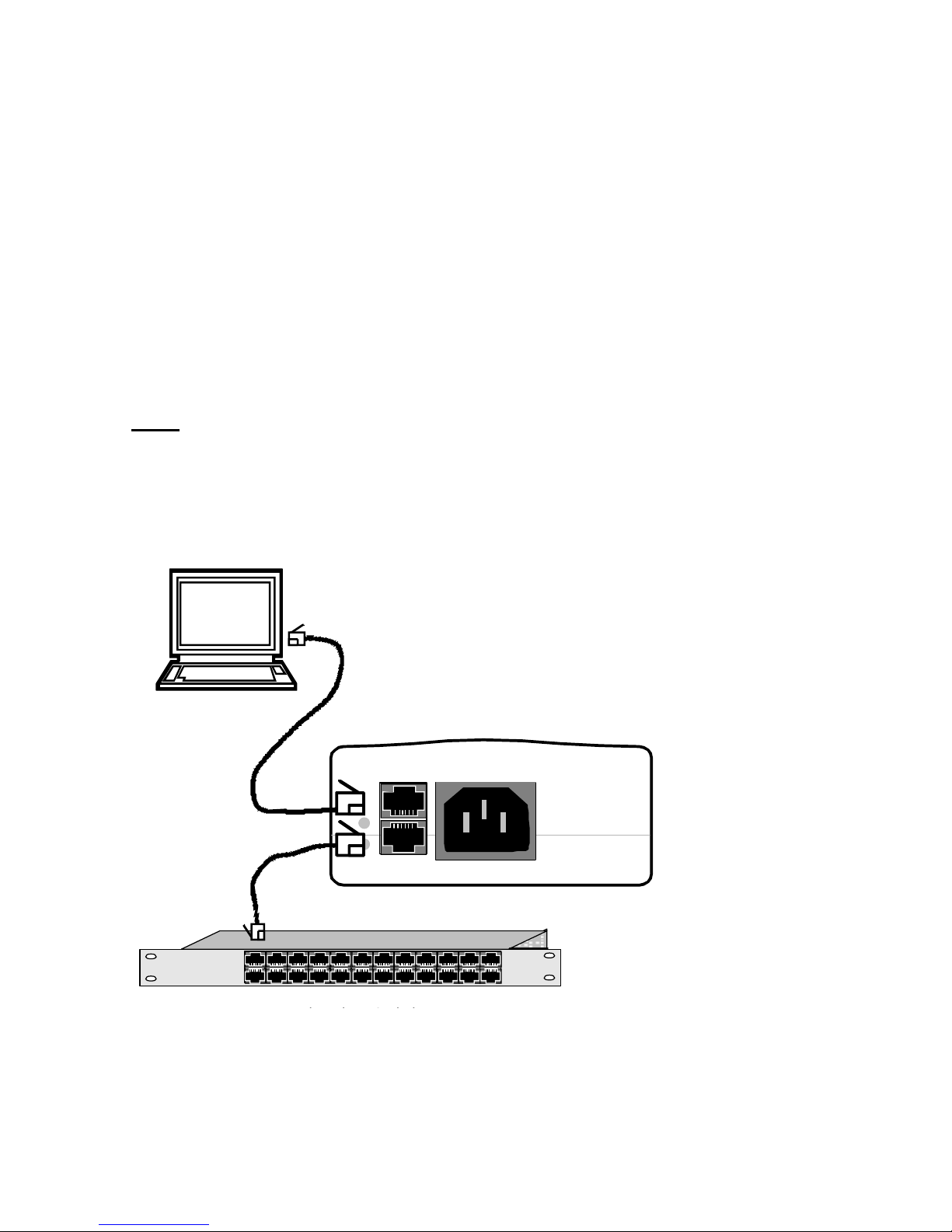
iBoot supports 10/100 Ethernet using unshielded twisted pair (Cat 5) cabling.
Two network jacks, with built-in hub are provided. They are auto-sensing for
10/100 and Uplink/Downlink. A Link LED next to each indicates when the
connection to the network is properly established. The built-in hub allows
one cable from the wiring closet to be used for both iBoot and the device it is
powering (or any other device). This greatly simplifies installation. Use of
both network jacks is optional.
Note: iBoot supports DHCP. If your network uses a DHCP server, it will
automatically assign an IP address when iBoot is firs powered up on the
network. If you do not use DHCP there are several other methods of
assigning an IP address. Please read the Configuration Section on page 8
for more details.
A/C Input
Networked Device
PC Workstation, Router Etc.
10/100 base-T
Unshielded
Twisted Pair
Page 6
Ver 2.0 and up iBoot Page 6
AC Power Connections
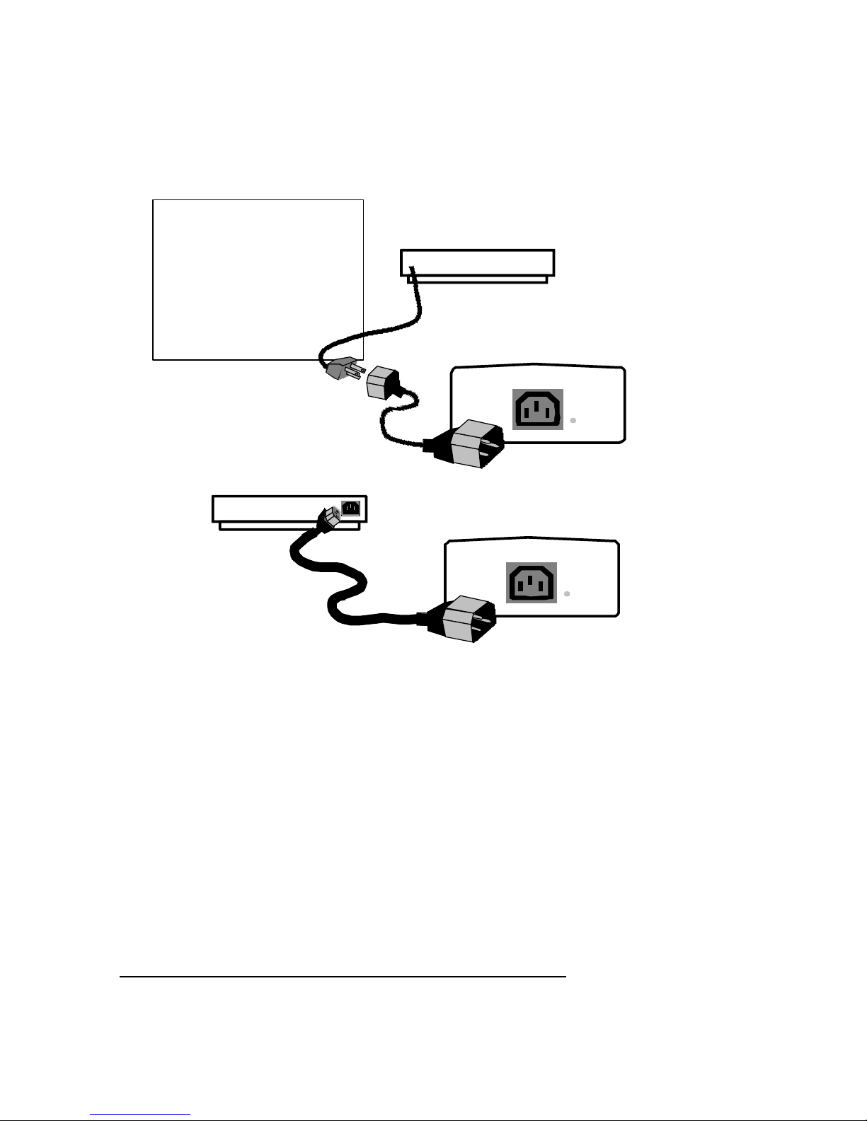
Connect the device to be powered ON and OFF to the IEC receptacle
marked Switched Outlet. A short IEC 320 to North American (NEMA 5-15)
power cord is included for connecting the iBoot outlet to the device to be
power controlled.
If a cord with a different terminating recepticle is required, be sure it is
properly rated and meets all the required local electrical standards. If the
device to be powered uses an IEC320 receipicle and detachable power cord,
an IEC to IEC extension cord can be used.
The iBoot can be connected to a power strip to allow simultaneous control of
multiple devices.
Make sure that the combined load of all controlled devices does not exceed
12 Amps for 105-125VAC or 10 Amps for 210-240VAC.
An LED Indicator next to the Switched Outlet will be On to indicate that the
power is On at that outlet. This LED will turn Off to indicate that the power to
the switched outlet is Off.
Switched
Outlet On
Connect Device to be Powered to iBoot
Use either:
IEC to NEMA Extension Cord
(supplied)
- OR IEC to your country specific
outlet (not supplied)
- OR IEC to IEC Extension Cord
(not supplied)
IEC to IEC
Extension Cord
Switched
Outlet On
IEC to NEMA
Extension Cord
Power Controlled Device
105-125 VAC 12A
210-240 VAC 10A
105-125 VAC 12A
210-240 VAC 10A
Page 7
Ver 2.0 and up iBoot Page 7
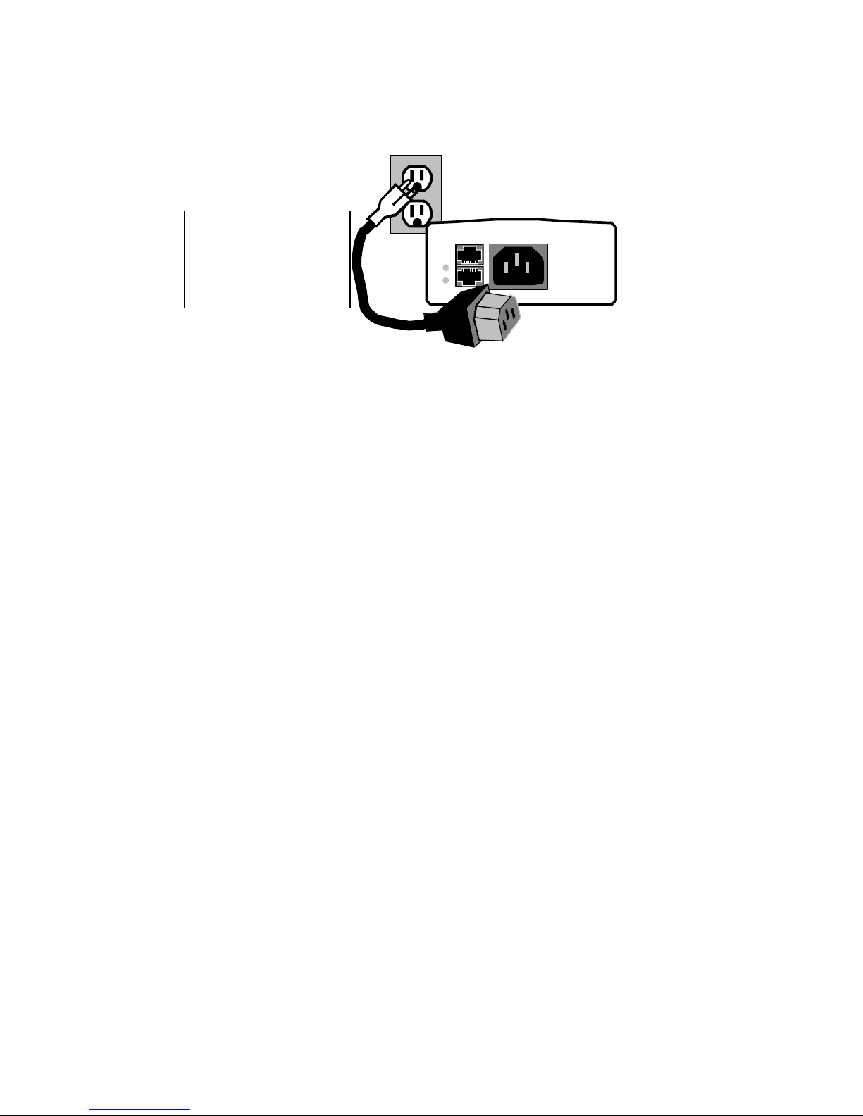
Connect the supplied power cord to the connector labeled AC Input, and the
other end to your AC source. If a power cord with a different terminating
plug is required, be sure it is properly rated and meets all the required local
electrical standards.
Uplink
Downlink
A/C Input
Connect to Power
Source
Use Included Cord for
North America. For other
locations, use locally
approved power cord.
Page 8

Ver 2.0 and up iBoot Page 8
iBoot Configuration
Setting I/P Address
Consult your Network Administrator to determine the appropriate IP address.
The IP address can be set in any of four ways:
1. Automatically from a DHCP Server
2. Web Browser via the Set-up Page
3. ibootrst.exe Program from Dataprobe
4. ARP / Ping
iBoot comes with factory installed IP address 192.168.1.254. and ready to
accept a new IP address from a DHCP Server. If you network has a DHCP
server, it will automatically assign an IP address to iBoot the first time it is
connected and powered up.
1. Setting the IP address from a DHCP Server
A DHCP server will automatically assign an IP address (dynamic address) as
well as Subnet Mask and Gateway to the iBoot. If you power up iBoot
without a fixed (static) IP address, the DHCP server will be able to assign an
IP address. This is the factory default setting for iBoot. Once an IP address
is assigned, you must check the DHCP server to see what address is
assigned to iBoot.
If you set the IP address using another method, the address becomes static.
To return iBoot to dynamic addressing using DHCP, change the IP address,
using the web browser to 0.0.0.0
2. Setting the IP address using Web Browser
To set the IP address using a Web Browser, connect the ethernet connection
to your local network and apply power to iBoot.
Open your browser and access iBoot by entering the default (192.168.1.254)
or current IP address into your browser's Address window. Enter the
password (the factory default is PASS). Click on Setup and follow the
instructions on Page 13.
Page 9
Ver 2.0 and up iBoot Page 9
3. Setting the IP address using the ibootrst.exe
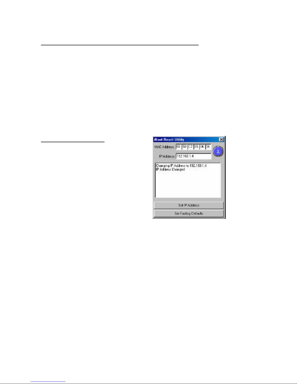
Dataprobe provides an iBoot Reset Program; ibootrst.exe to easily reset the
IP address, as well as set the factory defaults in the event the security code
is lost. Obtain ibootrst.exe from Dataprobe’s web site.
All iBoot tools are available at: www.dataprobe.com/power/iboottools.html
To use ibootrst.exe, the computer running the program must be on the same
subnet and network segment as the iBoot is to be programmed to. Same
subnet can be directly connected or connected through Ethernet hubs. (NOT
routers or switches)
To use ibootrst.exe
Enter the MAC address found on the
underside of the iBoot and the desired IP
address. Click on the Set IP Address bar.
ibootrst.exe will confirm the proper setting
of the address. If you receive an error
message, check the MAC and IP
addresses.
Page 10

Ver 2.0 and up iBoot Page 10
4. Setting the IP address using ARP / Ping
The ARP technique uses a PC running a command line (DOS Window) to set
the IP Address. To set the IP address using ARP, connect the iBoot to your
local network and apply power. The IP address to be assigned to iBoot must
be use the same network segment as the computer assigning the address.
ARP does not work across routed or switched networks.
To set the IP address using ARP, the hardware (MAC) address must be
known. This address is located on the bottom of the unit. The syntax for the
MAC address is: nn-nn-nn-nn-nn-nn
Windows (98 and Later)
1. Open a DOS window. (Run:Command)
2. Type the following command:
arp -s <IP Address> <MAC Address>
Where <IP Address> is the desired IP address (in dotted decimal) for the
iBoot and the <MAC address> is the MAC Address of the iBoot. The
MAC Address of the iBoot is located on bottom of the unit.
Example: arp -s 63.211.86.165 00-50-c2-05-01-c1 <enter>
|- new IP addr. --| |----- MAC addr. ----|
3. Ping the iBoot to program the IP address into the iBoot.
Type: ping <IP Address>
If the ping command returns “host not responding” 4 times then the
address has not been programmed properly, or the IP or MAC Address
is incorrect. In either case repeat step 2. If the problem persists, contact
the Dataprobe Tech Support Hot Line.
4. Delete the entry from the ARP cache by typing:
arp -d <IP Address>
5. Ping the iBoot to confirm that it has been programmed.
If the iBoot fails to respond, repeat steps 2-4 above. If the problem
persists, contact the Dataprobe support hotline.
Unix, Linux, MAC and others
Consult your systems administrator for information on other means of setting
an IP Address. The unit should be pinged after the IP Address has been set
to confirm proper operation.
Page 11
Ver 2.0 and up iBoot Page 11
Web Browser Operation
Password Protection
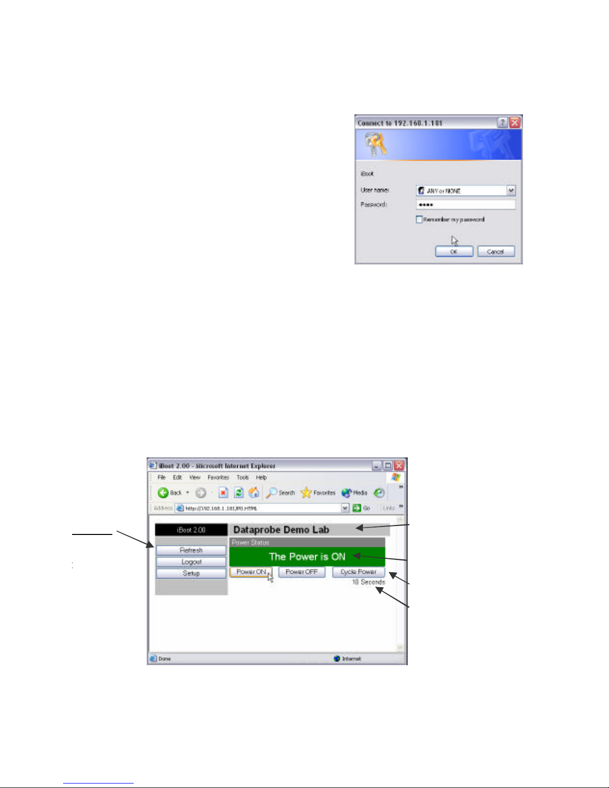
iBoot uses two passwords, one for normal
power control use and one that also provides
access to the setup functions. From the
factory, both passwords are the same.
(PASS)
Open your browser and enter the IP address
of iBoot into the address bar. If your have
changed the IP address by any of the
methods described, enter that address, otherwise, use the default IP address
192.168.1.254
Enter the default password PASS, or your password if it has been changed.
A Username is not required. When the proper password is received the
Control and Status Page is displayed.
Control and Status Page
Once the password is entered, the following page is displayed.
(Only one person can be connected to the iBoot at a time.)
Programmable
Device Name
Power Status
Action Buttons
Power Cycle
Time
(only seen if the
Page 12
Ver 2.0 and up iBoot Page 12
To control the power, click on the appropriate button. During power cycling,
the Power Status bar will indicate the temporary status, with a blue
background. Once the cycle is complete, the status bar will revert to its
original condition. To abort a power cycle, click on either Power On or Power
Off buttons. iBoot will assume the status selected.
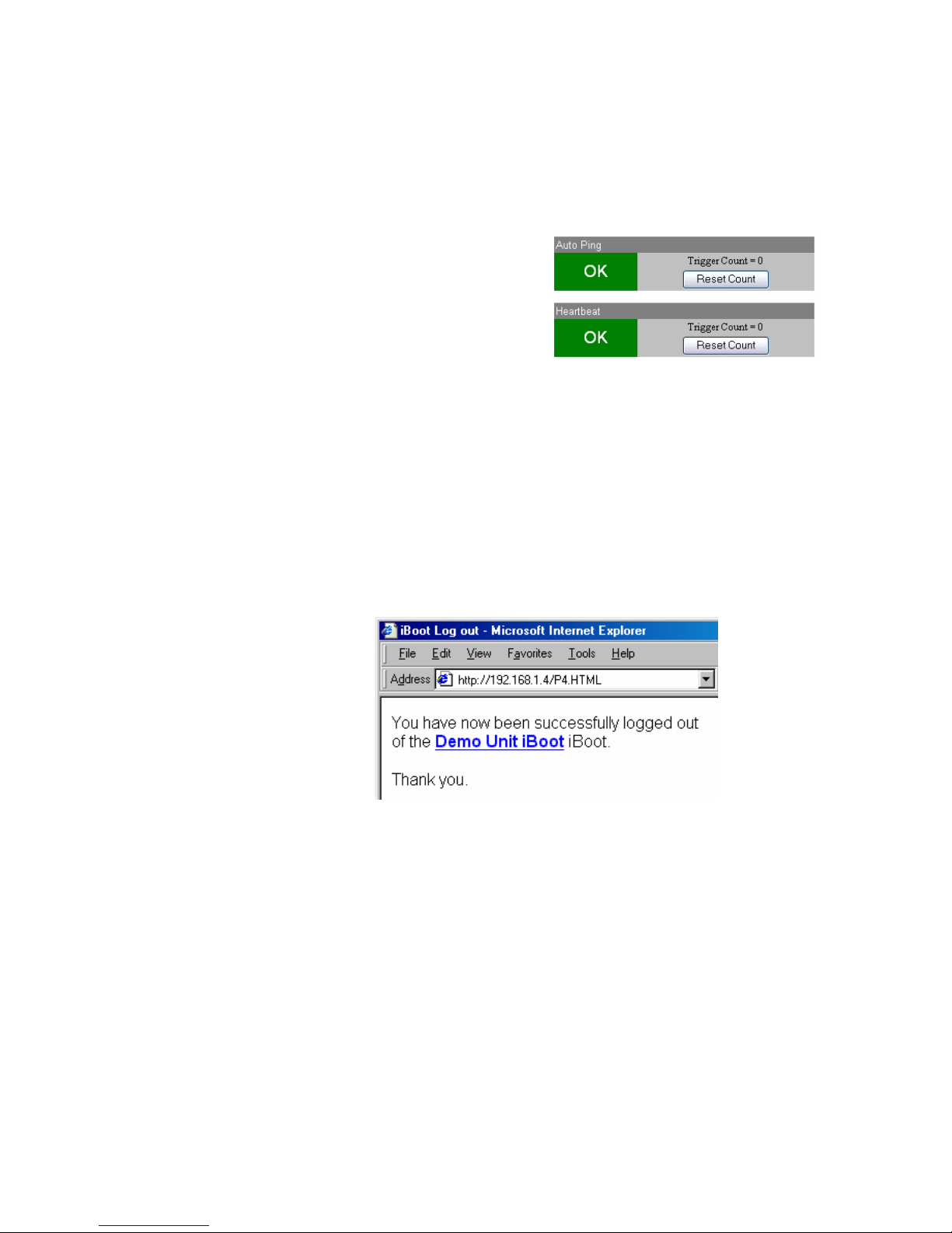
If the Auto-Ping or Heartbeat Features are in
use then the page will also display the
current status, OK or Triggered, for each,
with a counter of how many times that
feature was triggered. If connecting with the
Setup Password, a reset button for the
counter is provided. These features are described in greater detail in the
Advanced Operation section on page 16
Use the Refresh link to obtain the latest status of iBoot. Using your
browser's refresh button can lead to inadvertent power switching.
To access the Setup page, the Setup Password must be used for the initial
login. The factory default for the Setup Password, as well as the operation
password is PASS. Both passwords can be changed in Setup.
When you are finished with
iBoot, click on Logout. A
confirmation page will be
displayed. If you close your
browser window without first
clicking Logout, there will be a two
minute delay before you can reaccess iBoot.
iBoot uses an inactivity timer for security. When there is no activity for 2
minutes, the user is logged out and the password will need to be entered
again for access. This is to prevent accidental lockout by leaving the user
logged in.
Page 13
Ver 2.0 and up iBoot Page 13
iBoot Setup
iBoot setup section consists of several pages. Access any page via the
buttons on the left of the page. Each time a setting is changed click on the
Apply button for that page to save the changes in iBoot.
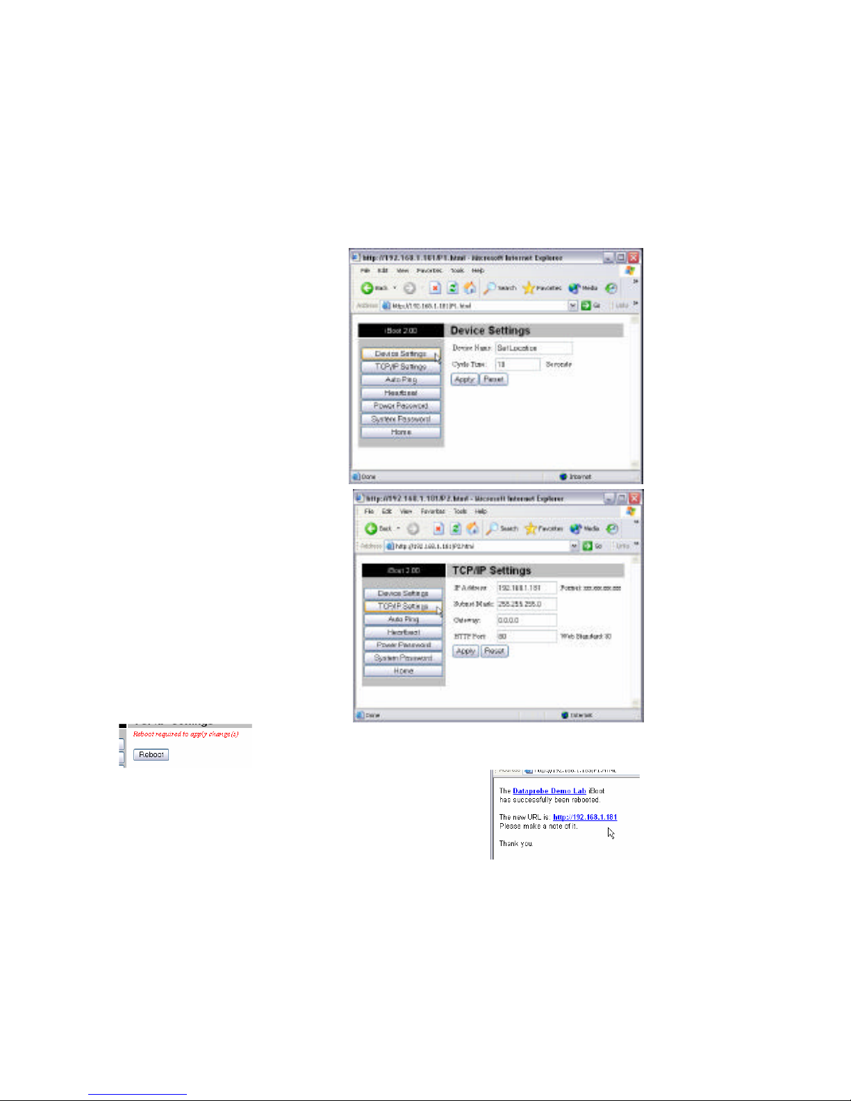
Device Settings
Device Name: Set a 20 Character
name to be displayed on the top of the
Home page. This assists in
identifying which iBoot is being
accessed.
Cycle Time: 0 to 999 seconds
power cycle time. This is the length of
time the power will be off during a
reboot, or on during a power burst.
TCP/IP Settings
IP address: Enter either a new IP
address, or address 0.0.0.0 to enable
Automatic IP addressing via DHCP.
Once you click Apply for this section,
also click the Reboot button that will
appear at the top of the page. The new
IP address will not take effect until the
unit is rebooted.
Upon Clicking Reboot, a page indicates the new URL for
the device. Use this new URL to access iBoot.
Subnet Mask: Change if required. Consult your network manager for more details.
This will be automatically set if using DHCP
Gateway: Change if required. Consult your network manager for more details. This
will be automatically set if using DHCP
HTTP Port: This setting is used to allow access to iBoot on a port other than the
Web standard Port 80. If the port is changed, you will need to identify the port
Page 14
Ver 2.0 and up iBoot Page 14
number when you enter iBoot's IP address into your browser: if the new port is 9100
then use address http://192.168.1.254:9100 to access iBoot.
After changing the port, a reboot is necessary. Consult your Network Administrator
for available port assignments. Click on the Reboot button at the top of the page to
install the new port.
Auto-Ping Setup
See Advanced Operation for Auto-Ping Setup
Heartbeat Setup
See Advanced Operation for Heartbeat Setup
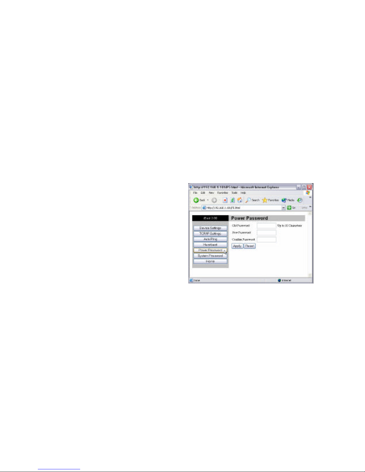
Power and System
Passwords
Two passwords are provided. The Power
Password allows access to the control of
iBoot, but not to the Setup functions.
When this password is used, the main
screen will not have a link to Setup. The
System Password allows access to both
the Main Screen and the Setup Screen.
The default for both Passwords is PASS.
Passwords can be up to 10 characters
long and is case sensitive.
Enter the current password then the new password twice to confirm. Click Apply for
each password being changed.
Page 15
Ver 2.0 and up iBoot Page 15
OOPS - I forgot my Password
Well, we told you to remember it, but we understand. You can reset iBoot to
its factory default conditions.
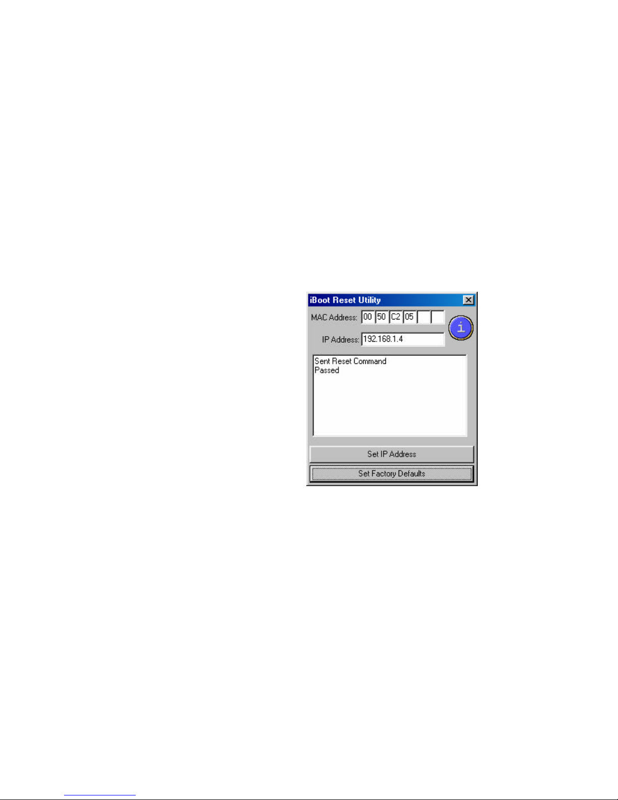
Dataprobe provides an iBoot Reset Program for Windows™. You will need
to have physical access to the iBoot as well as network access.
To reset the factory defaults including the password, use ibootrst.exe
All iBoot tools are available at: www.dataprobe.com/power/iboottools.html
For security purposes, you will need to power up the iBoot and complete the
reset to factory defaults within two minutes.
1. Run ibootrst.exe. Enter the
current IP address of
iBoot.
2. Remove and replace the
power to iBoot. You have 2
minutes to complete step 3.
3. Click on the Set Factory
Defaults button.
This process does not change the IP
address. It will change all other
settings, including Location Name, AutoPing and Heartbeat to their factory
defaults.
Page 16
Ver 2.0 and up iBoot Page 16
Advanced Operation
Auto-Ping
The Auto-Ping feature allows iBoot to automatically detect failed equipment
and perform a timed reboot or other power control function (like turning on an
indicator or siren). You set any IP address to be periodically Ping'ed. When
iBoot no longer detects a response from the address, the programmed power
control function is actuated.
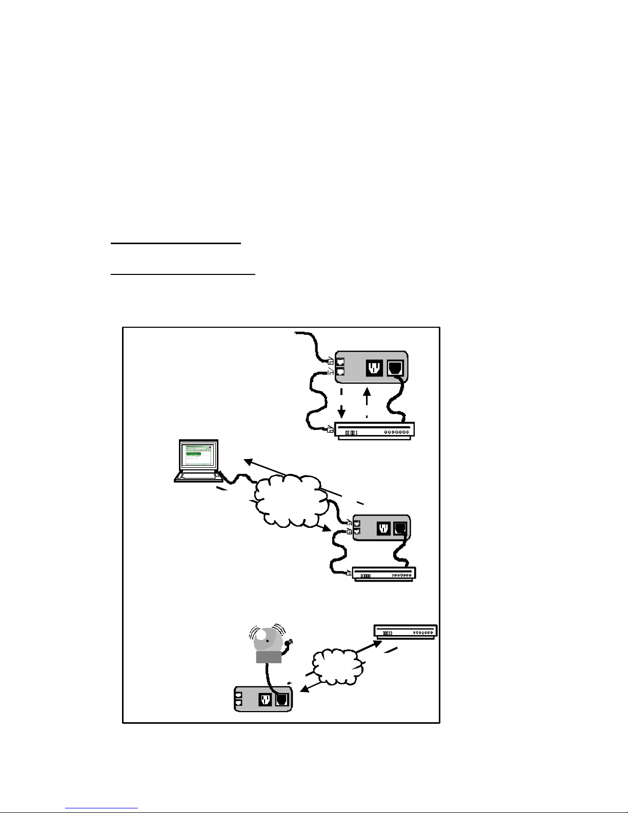
♦ Use Auto-Ping Locally: Put iBoot next to the device to be monitored and
reboot it automatically when it no longer responds.
♦ Use Auto-Ping Remotely: Put iBoot at a central facility to monitor a
remote system and power up an alert when the remote device no longer
responds.
Uplink
Downlink
Pwr Out
Pwr In
Local Ping
Example:
iBoot monitors local device
and automatically reboots
it if there is no response
Ping
Response
Uplink
Downlink
Pwr Out
Pwr In
Ping
Response
Remote Ping
Example 1:
iBoot monitors network
connection and reboots
when there is no response
Example 2:
iBoot monitors remote
device and powers up
alarm when there is
no response
Inter- or
Intra- Net
Uplink
Downlink
Pwr Out
Pwr In
Response
Ping
Page 17
Ver 2.0 and up iBoot Page 17
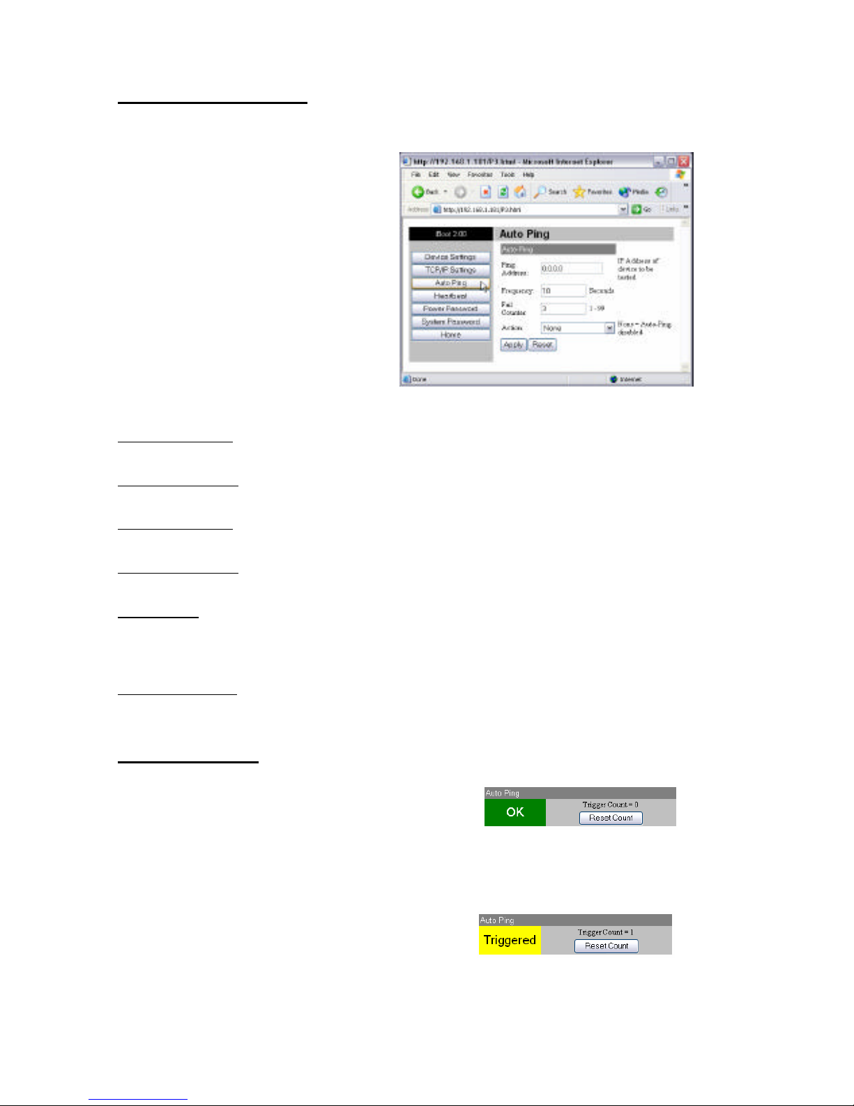
Auto-Ping Setup Page
Ping Address: Enter the IP address of the device to be pinged.
Ping Frequency: Enter 1 to 999
seconds. The ping will go out to the
selected device this often.
Fail Counter: Enter 1-99 times the ping
needs to fail consecutively before the
selected action is taken.
Action: select from
♦ None (Auto Ping not used)
♦ Power On – Latch
♦ Power On – Follow
♦ Power Off – Latch
♦ Power Off – Follow
♦ Power Cycle
♦ Power Cycle Once
Power On – Latch: Upon loss of ping response, iBoot will power on and remain so until changed
via the web, ibootctl.exe or direct messaging.
Power On – Follow: Upon loss of ping response, iBoot will power on. When the ping response
returns, iBoot will power off.
Power Off – Latch: Upon loss of ping response, iBoot will power off and remain so until changed
via the web, ibootctl.exe or direct messaging.
Power Off – Follow: Upon loss of ping response, iBoot will power off. When the ping response
returns, iBoot will power on.
Power Cycle: Upon loss of ping response, iBoot will cycle the power. iBoot will wait the Ping
Frequency; if the response does not return, the power will be recycled again. This will continue
until the ping response returns or Auto Ping is turned off. Make sure your Auto Ping frequency is
longer than the time required to reboot your device.
Power Cycle Once: Upon loss of ping response, iBoot will cycle power one time. It will not cycle
again automatically until the ping response returns and is lost again.
Using Auto-Ping
With Auto-Ping operational, the main iBoot
page will display the current status of this
feature. The status will be OK to indicate
that iBoot is receiving responses to the ping, or that the fail counter has not
yet been exceeded.
If the fail count has been exceeded, the
status will change to Triggered. The
Trigger Counter indicates the number of
times the Auto-Ping feature has been triggered. A counter reset button is
provided when logging in with the System password.
Page 18
Ver 2.0 and up iBoot Page 18
Heartbeat Monitor
Like Auto-Ping, the Heartbeat monitor allows iBoot to monitor one or more
devices and take action when these devices fail. With the Heartbeat monitor
enabled, iBoot will expect a network message on a regular interval. When it
misses a user defined number of intervals, it will perform its programmed
action.
Use the heartbeat to insure that you server is running. When it crashes, it
will be automatically rebooted.
The
heart
beat
can
be
gene
rated
in
any
of
seve
ral
ways
;
• A Windows executable program that will run as a tray applet that will
transmit either continuous heartbeats to an iboot.
• A Windows .dll file is also available for use by Windows™ applications.
• A Windows executable that will run as a tray application, monitor a
specific process. If the monitored process stops responding the application
will stop transmitting the heartbeat to the iBoot.
• The Heartbeat Protocol will allow developers to imbed this capability
directly into their software products.
All heartbeat tools are available at
http://www.dataprobe.com/power/iboottools.html
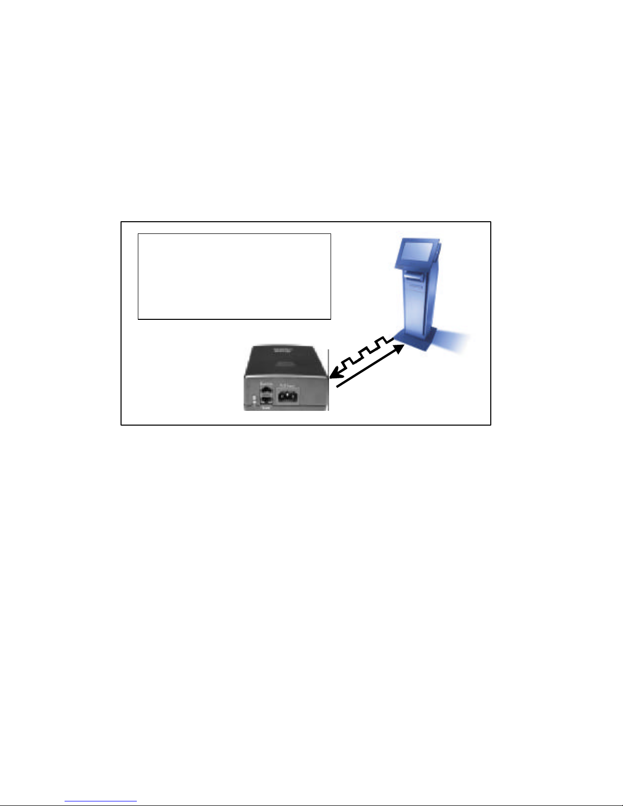
Heartbeat
Confirmation
Example:
Kiosk generates heartbeat at a regular
interval to inform iBoot that operations
are normal. When kiosk crashes,
heartbeat stops and iBoot automatically
reboots the kiosk
Page 19
Ver 2.0 and up iBoot Page 19
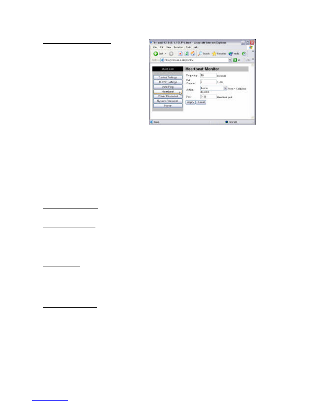
Heartbeat Setup Page
Frequency: Enter 1 to 999
seconds. If the heartbeat is not
received within this time it will
increment the counter.
Fail Counter: Enter 1-99 times
the heartbeat needs to fail before
the selected action is taken.
Action: select from
♦ None (Heartbeat not used)
♦ Power On – Latch
♦ Power On – Follow
♦ Power Off – Latch
♦ Power Off – Follow
♦ Power Cycle
♦ Power Cycle Once
Power On – Latch: Upon loss of heartbeat, iBoot will power on and remain
so until changed via the web, ibootctl.exe or direct messaging.
Power On – Follow: Upon loss of heartbeat, iBoot will power on. When the
heartbeat returns, iBoot will power off.
Power Off – Latch: Upon loss of heartbeat, iBoot will power off and remain
so until changed via the web, ibootctl.exe or direct messaging.
Power Off – Follow: Upon loss of heartbeat, iBoot will power off. When the
heartbeat returns, iBoot will power on.
Power Cycle: Upon loss of heartbeat, iBoot will cycle the power. iBoot will
wait the Frequency time; if the heartbeat does not return, the power will be
recycled again. This will continue until the heartbeat returns or Heartbeat
Monitor is turned off. Make sure your Frequency is longer than the time
required to reboot your device.
Power Cycle Once: Upon loss of heartbeat, iBoot will cycle power one time.
It will not cycle again automatically until the heartbeat returns and is lost
again.
Page 20
Ver 2.0 and up iBoot Page 20
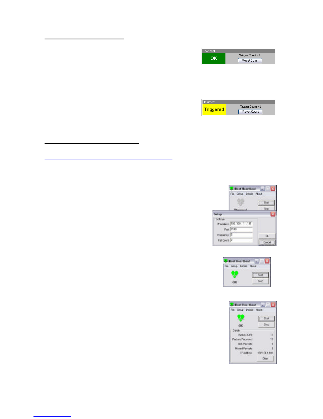
Using Heartbeat Monitor
With Heartbeat operational, the main iBoot page will display the current
status of this feature. The status will be OK to
indicate that iBoot is receiving heartbeats, or that
the fail counter has not yet been exceeded.
If the fail count has been exceeded, the status will
change to Triggered. The Trigger Counter
indicates the number of times the Heartbeat
feature has been triggered. A counter reset
button is provided when logging in with the
System password.
Using the Heartbeat Program
Download the Heartbeat program at
www.dataprobe.com/power/iboottools.html
This program will generate heartbeats to one iBoot at regular intervals. It will
also monitor a response back from iBoot to insure proper communication.
Run the program. To begin use, first click Setup.
Enter the IP address for the iBoot, the Port configured
for the Heartbeat in iBoot, the frequency of
heartbeats, and a Fail Count. This fail count does not
affect the performance of the iBoot. It is used to
indicate when the iBoot has stopped responding to
the heartbeats.
To begin sending heartbeats, click Start.
The heart icon will change to green to indicate
responses received back from iBoot, or red, to
indicate a failure of communication.
Detail about the communication between iBoot and
the Heartbeat program can be viewed by clicking on
the Details menu. The following information is
presented:
• Packets Sent: The number of heartbeats set
to iBoot
• Packets Received: Number of valid
responses received back from iBoot.
• NAK Packets: Response from iBoot
indicating that the packet was received, but corrupted.
• Missed Packets. Heartbeats that were not responded to by iBoot.
To stop the heartbeats, click Stop. To reset all the counters, click Clear.
Page 21

Ver 2.0 and up iBoot Page 21
Control Programs
Dataprobe provides a remote control program to control iBoot directly. This
program is useful for creating simple desktop icons for specific power
functions for one or more iBoots. It can also be run from a command line
and can be called by other programs. (Batch files etc.)
For example, ibootctl.exe can be called from server monitoring programs
such as WhatsUp Gold™, Servers Alive™ or any program that provides for
an external program to be run upon loss of a server.
The iBoot Control Center program allows control of multiple iBoot units. This
program provides the ideal means of monitoring and managing a large
number of iBoots distributed throughout your organization.
Both programs are available from Dataprobe at
www.dataprobe.com/power/iboottools.html
Direct TCP/Telnet Control
For application developers, iBoot also supports control via direct TCP
communications. To control iBoot in this manner requires opening a socket
to iBoot and sending specific commands. Information on the required
techniques and protocol are available at Dataprobe's web site at
www.dataprobe.com/power/iboottools.html. Dataprobe can provide perl
scripts and other programmer resources to assist in integration of iBoot into
any system.
Page 22

Ver 2.0 and up iBoot Page 22
Specifications
Model
iBoot A/C Power Control Module Ver 2.x SKU: 1410010
Physical
Height 2.25 in.
Width 4.50 in.
Depth 6.00 in.
Weight 1.25 lb.
AC
Input: 3 Prong, Male, IEC 320 input connector.
Input Cord Spec...16AWGX3C 10A 250 UL/CSA/VDE Rated
(1.25mm2X3C)
Voltage Range: Auto Sensing 105-240 VAC
Switched Receptacle: 3 Prong Female IEC
Capacity: 12 Amps Max at 105-125 VAC,
10 Amps Max at 210-240 VAC
Network
Dual 10/100 Unshielded Twisted Pair Ethernet Jacks.
Dual Jack Hub Built-in
IP Addressed
Internal HTTP Web Server,
Forms Processing Browser required
User Settings Record your Setup here for reference
Location
MAC Address
IP Address
Subnet Mask
Gateway
HTTP Port
Auto-Ping Address
Auto-Ping Port
Heartbeat Port
Notes:
Page 23

Ver 2.0 and up iBoot Page 23
TECHNICAL SUPPORT, RETURNS and WARRANTY
Dataprobe Technical Support is available 8:30AM to 5:30PM ET to assist you in the installation
and operation of this product. To obtain Technical Support call our Tech Support Hotline at 201967-8788, or Email us at [email protected]. Please have the following information available
when you call:
• Model of Product
• Serial, Lot and/or Version Numbers
• Data of Purchase
• Name of Seller (if other than Dataprobe)
If you purchased this product through an Authorized Dataprobe Reseller, you should contact
them first, as they may have information about the application that can more quickly answer your
questions.
WARRANTY
Seller warrants this product, if used in accordance with all applicable instructions, to be free from
original defects in material and workmanship for a period of One Year from the date of initial
purchase. If the product should prove defective within that period, Seller will repair or replace
the product, at its sole discretion.
Service under this Warranty is obtained by shipping the product (with all charges prepaid) to the
address below. Seller will pay return shipping charges. Call Dataprobe Technical Service at
(201) 967-8788 to receive a Return Materials Authorization (RMA) Number prior to sending any
equipment back for repair. Include all cables, power supplies and proof of purchase with
shipment.
THIS WARRANTY DOES NOT APPLY TO NORMAL WEAR OR TO DAMAGE RESULTING
FROM ACCIDENT, MISUSE, ABUSE OR NEGLECT. SELLER MAKES NO EXPRESS
WARRANTIES OTHER THAN THE WARRANTY EXPRESSLY SET FORTH HEREIN.
EXCEPT TO THE EXTENT PROHIBITED BY LAW, ALL IMPLIED WARRANTIES,
INCLUDING ALL WARRANTIES OF MERCHANT ABILITY OR FITNESS FOR ANY
PURPOSE ARE LIMITED TO THE WARRANTY PERIOD SET FORTH ABOVE; AND THIS
WARRANTY EXPRESSLY EXCLUDES ALL INCIDENTAL AND CONSEQUENTIAL
DAMAGES.
Some states do not allow limitations on how long an implied warranty lasts, and some states do
not allow the exclusion or limitation of incidental or consequential damages, so the above
limitations or exclusions may not apply to you. This warranty gives you specific legal rights, and
you may have other rights which vary from jurisdictions to jurisdiction.
WARNING: The individual user should take care to determine prior to use whether this device is
suitable, adequate or safe for the use intended. Since individual applications are subject to
great variation, the manufacturer makes no representation or warranty as to the suitability of
fitness for any specific application.
Dataprobe Inc.
11 Park Place
Paramus, NJ 0765
Page 24
More Power Control Solutions
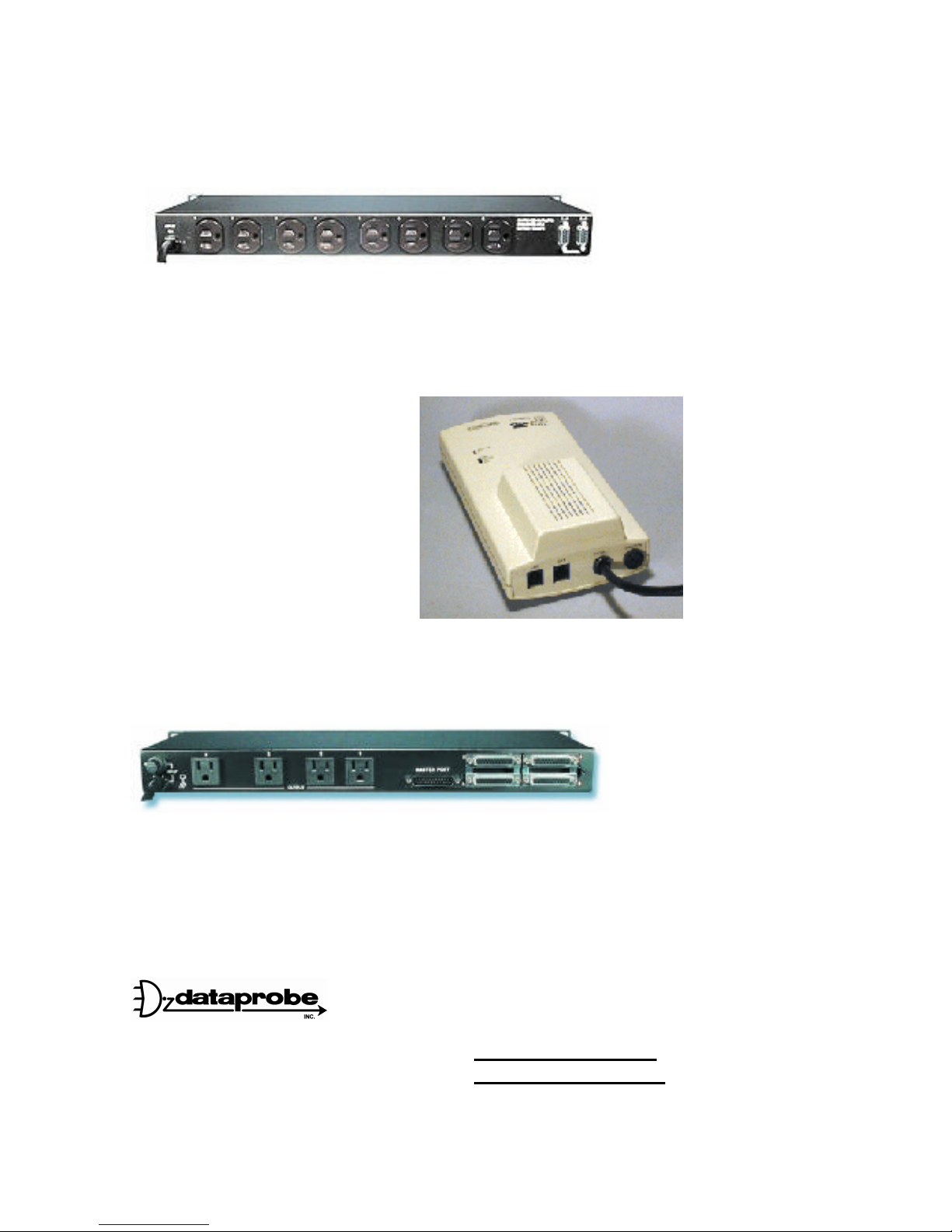
8 Outlet Remote Control Power Strips
Rack Mounted 8 outlet power strips can be controlled by Web / Telnet / Modem / Serial or
DTMF dialing tones. Visit www.dataprobe.com/power/8outlets.html
Phone Controlled Power Switch
PowerPAL offers remote control of a
single A/C outlet using any tone dial
telephone. PowerPAL connects to an
existing dial line, and any telephone
equipment; phone, fax, modem.
Normal calls pass transparently
through PowerPAL; only when
special access codes are detected by
PAL will the power control functions
be enabled. User selectable security,
call processing and power control
features are examples of such
capabilities. Visit www.dataprobe.com/power/ppal.html
Remote Power Control + Console Port Access
Access four console ports and reboot four devices with this integrated Remote Site Manager.
From one call you can switch between any of the four serial ports or access any of the A/C outlets
for complete access and control. The internal modem option turns this unit into a completely
integrated system that will minimize costly trips to remote sites. Visit
www.dataprobe.com/power/4pk415.html
11 Park Place
Paramus, NJ 07652
201-967-9300
www.dataprobe.com
[email protected]
Doc: iBoot20_v030731E
© 2003 Dataprobe, Inc. All rights reserved
 Loading...