


DAXOM boilers provide following sufficiency
Gas Appliances Directive 2009/142/EEC
Boiler Efficiency Directive 92/42/ECC
Electromagnetic Compability Directive 2004/108/CE
Low Voltage Directive 2006/95/CE

CONTENTS
1.SECURITY INFORMATIONS AND WARNINGS .......................................................................................... 4
1.1 Warnings ......................................................................................................................................... 4
1.2 Warnings .......................................................................................................................................... 4
2 GENERAL INFORMATIONS ...................................................................................................................... 5
2.1 General Information ................................................................. Hata! Yer işareti tanımlanmamış.
2.2 Giving Information to Customer While Deliver the Device ............................................................ 5
2.3 Description ...................................................................................................................................... 5
2.4 Device Dimensions .......................................................................................................................... 6
2.5 Boiler Installation Distances ............................................................................................................ 8
2.6 Inside Structure Of the Device ........................................................................................................ 9
2.7 Technical Specificitions .................................................................................................................. 10
3 INSTALLATION....................................................................................................................................... 12
3.1 Installation ..................................................................................................................................... 12
3.2 Plumbing ........................................................................................................................................ 12
3.3 Natural Gas Line ............................................................................................................................ 12
3.4 Electrical Installation ..................................................................................................................... 13
3.5 Pipe Line ........................................................................................................................................ 13
4 SAMPLE INSTALLATION DIAGRAMS...................................................................................................... 15
4.1 Heating System with Boiler ........................................................................................................... 15
4.2 Cascade Heating System Diagram with Solar System ................................................................... 16
5 PIPE IMPLEMENTATIONS ...................................................................................................................... 17
6 ELECTRICAL PROJECT ............................................................................................................................ 18
7. ACCESORIES ......................................................................................................................................... 21
8 FIRST OPERATION ................................................................................................................................. 23
8.1 Heating Mode Selection ................................................................................................................ 23
8.2 Setting Time Programme ............................................................................................................... 23
8.3 Setting Room Temperature ........................................................................................................... 23
8.4 Mannual Using ............................................................................................................................... 23
8.5 Reset .............................................................................................................................................. 23
9 MAINTENANCE ..................................................................................................................................... 23
9.1 Periodic Controls that Users Must Be Made ................................................................................. 24
9.2 Service Maintenance Prosedures .................................................................................................. 24
9.3 Maintenance Warning Codes ........................................................................................................ 25

1. SECURITY INFORMATION AND WARNINGS
1.1WARNINGS
- This user manual is inseparable piece of your
device Please keep it in a place near the device
that is immediately got. In case of any lost or
damage, please supply new one with Isı Cihazları
Company.
- DAXOM / Naviels wall hung condensing boiler
must be installed by authorized person according
to the closing rules.
- Boiler must not be used except production
purpose. Manufacturer Company rejects
responsibilities of injuries and economic damages
cause from wrong installation of boiler, wrong
setting or not maintenance timely.
- When you open the packet box of the device,
firstly control if any damage at the device or not. In
case of any problem contact with the seller
company.
- Before making the installation of the device,
firstly be sure that plumbing is cleaned. Dirtiness
that is occurring inside the heating cycle causes
low efficiency and noise operation.
- Please careful about leaving min space while
making installation for interfere the system.
- Control the water level periodically from water
level indicator occurs at the boiler. Indicator must
be over 1 bar.
- If you observe water leakage at the boiler, close
the water valve immediately and contact with
authorized service.
- If the boiler will not be used for a long time, cut
off the electric supply and gas inlet of the boiler. If
there is freezing risk at water installation or boiler
system, you need to discharge water inside the
plumbing.
- Control the operation of the air conditioner of the
place that the boiler is placed at regular intervals.
-Boiler is designed for using at interior place. It is
not suitable for using at open environment places.
- Because of boiler is condensing type, be careful
that the condensing discharge line is connected
and not blocked.
- Make the authorized service maintenance your
boiler at least once a year.
1.2 Warnings
- If gas or smoke smell are sensed, do not operate
any electrical devices in case of gas leakage,
ventilate environment by closing gas valve and
contact with authorized people. Do not smoke at
the environment in no sense.
- Do not touch cover of boiler with wet hands or
bare foot?
- Do not certainly pull and twist or force cables
connected to boiler even it is no energy.
- Freezing prevention system occurs at the boiler
Because of this, do not cut off electric and close
the gas valve of boiler when the external
environment is cold.
- Do not absolutely start boiler cleaning before cut
off main electric supply.
- Do not keep flammable or explosive materials at
the boiler room.
- Do not certainly interfere safety device occurred
on the boiler. Do not deactivate for short term or
continuously.
-Be sure that pipe fitting is made correctly and not
leak gas to the environment.
-Do not certainly operate heater without water
inside plumbing.

2 GENERAL INFORMATION
2.1 General Information
-The user manual which is given with condensing
boiler is inseparable piece of the device. Because
of this, it must be kept carefully and it must be
kept in a place near the device that is immediately
got. In case of any lost or damage, it must be
supplied from DAXOM Company.
Any person except authorized person or person
who had education from authorized service must
not interfere to device.
Considering warnings inside the manual is
important for both your safety and safe operation
of the device.
Device must be operated by installing stated inside
the manual under necessary conditions of safety
and operating. Under these conditions DAXOM
trade mark boiler is less than 2 years warranty
cover by Manufacturer Company.
Using the device out of its purpose, using different
from conditions stated inside the manual, interfere
by unauthorized person and problems which cause
because of external factors such as (gas, electric
and etc) are evaluated as out of warranty.
The lifetime of the device determined by Ministry
of Customs and Trade is 10 years in case of obey to
user instructions. In the meantime manufacturer
and Seller Company obliged to meet service and
spare parts of user.
The first operation and controls of boiler must be
done by authorized service and product guarantee
must be done. Devices which are using before
doing warranty start by authorized service will be
no warrantable.
2.2 Giving Information to
Customer While Deliver the Device
Tell consumer about operation of the device,
significant points that must be careful before
operation of the system or during operation of
system, importance of periodic maintenance in
terms of performance and efficiency of device and
inform about maintenance agreement.
Explain user that necessary services contact
information is found inside user manual.
Deliver the user manual to consumer and tell him /
her that are needed to keep near the boiler.
2.3 Description
DAXOM Navidens boilers are condensing boilers
that are used by installing wall are designed as
heating water inside heating system with NG or
LPG and also meet the need heat demand of a
boiler through this water.
DAXOM Navidens condensing boilers are also
enable for coupled solar energy to boiler system.
On the other hand, they have necessary
substructure for heating swimming pools.
There is burner inside the boiler which provides
Combustion with aluminum casting hot bulb and
premix technology.
There is flow meter gas valve on the boiler which
determines and stops quantity of gas that obtains
necessary energy for heating. There are sensors at
the system for following inlet and outlet water
temperatures for the aim of determination of
boiler operation capacity.
On the other hand, for the aim of security control
of the system there are bottom water pressure
control wind pressure switch, drain valve, safety
thermostat and pipe gas temperature sensor.
Boilers’ ignition, flame monitoring, capacity
control, safety device and operation functions
occur by electronic control card.
It can be operated as connected external room
thermostat.
By the LCD panel on the boiler information can be
followed concerning to operation of the system.
(Instant operation capacity, boiler inlet, outlet
temperatures, etc)
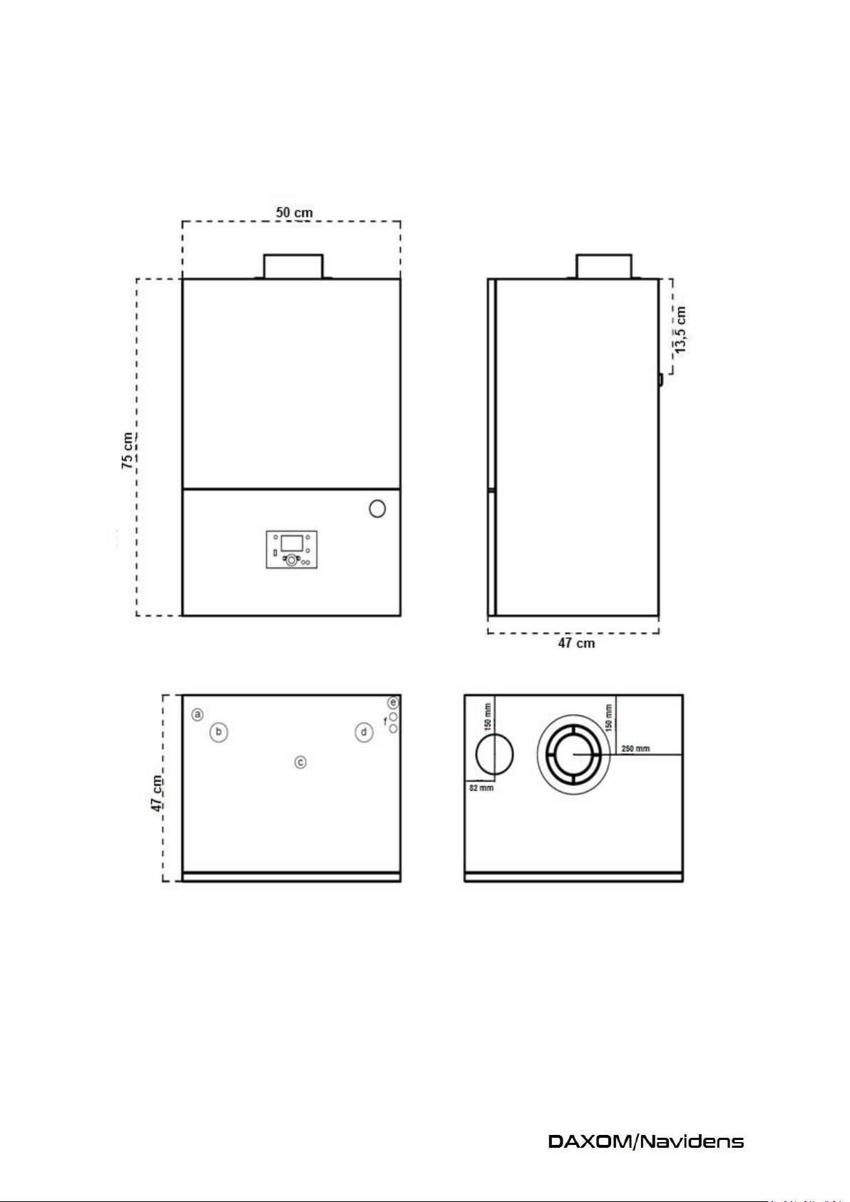
2.4 Dimension of Device
Navidens 50-70
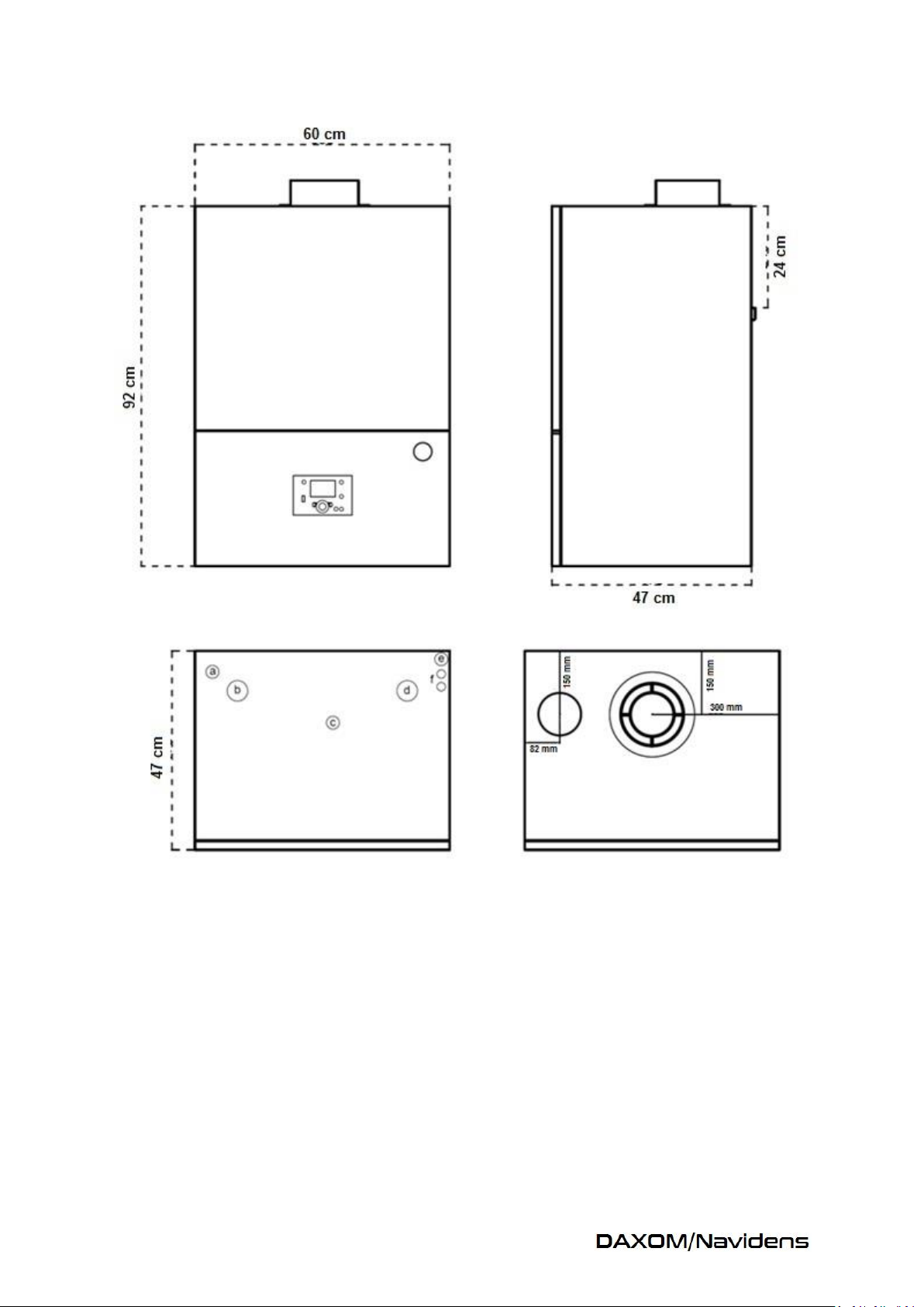
Navidens 125-145
a: Safety Valve Outlet
b: Plumbing Return
c: Gas Inlet
d: Plumbing Exit
e: Condensing Outlet
f: Cable Entry
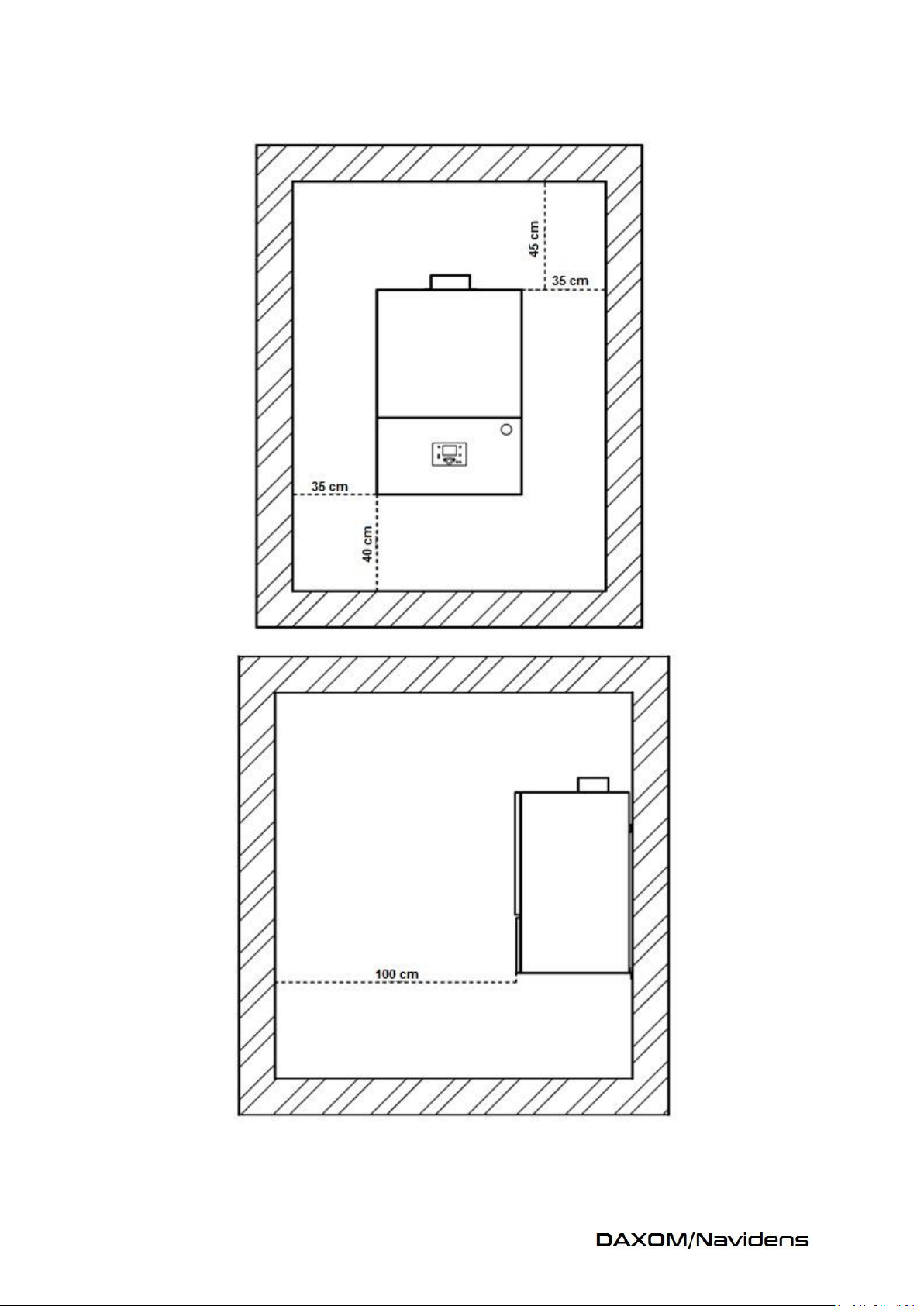
2.5 Boiler Installation Distances

2.6 Inside Structure of the Device
1- Automatic Air Relief Cock
2- Safety Thermostat
3- Manual Air Relief Cock
4- Outlet Water Temperature Sensor
5- Ionization Electrode
6- Ignition Electrode
7- Sight Glass
8- Combustion Space
9- Pipe Gas Temperature Sensor
10- Condensation Tank
11- Siphon
12- Electronic Control Card
13- Circulation Pump
14- Safety Valve
15- Return Water Temperature Sensor
16- Manometer Hour Connection
17- Pressure Switch
18- Pulse Ignition System
19- Gas Valve
20- Air Suction Inlet
21- Air Fan

UNIT
NAVİDENS50
NAVİDENS70
NAVİDENS125
NAVİDENS145
Fuel Type
G20/G30
Pipe Type
B23,C13,C33,C43,C83
Max Operation Pressure
bar 6 6 6 6
Maximum Operation
Temperature
⁰C
85
85
85
85
Fuel Consumption
max
lt/min
89,5
114,5
203
237
min
lt/min
18,3
20,9
29,5
38,3
Heat Input
max
kW/h
50
66
117
136,7
min
kW/h
10
12
17
22
Heat Power
Nominal Heat Load
30-50 ⁰C
kW/h
52,5
68
125
145
Nominal Heat Load
80-60 ⁰C
kW/h
48,5
64
112,5
131,15
Efficiency
Min Heat Load
30-50 ⁰C
%
107,6
108
106,4
106,7
Nominal Heat Load
30-50 ⁰C
%
105
104
103,7
102,8
Partial Load
30 ⁰C % 108
107
106,85
106,08
Nominal Heat Load
80-60 ⁰C
%
97
97
96,12
95,94
Min Heat Load
80-60 ⁰C
%
95
96
94
95
Efficiency Class
☆☆☆☆
Pipe Dates
Pipe Pressure
Pa
150
135
240
210
Exhaust Gas Flow Rate
Max
g/sec
22
29
51,5
60
Min
g/sec
4,5
5,4
7,5
9,7
Combustion Values
CO2 Emission ( G20 )
Max Load
%
9,3
9,9
9,4
9,5
Min Load
%
9,8
9,6
9,7
9,6
CO2 Emission ( G30 )
Max Load
%
10,9
11,1
11
11,2
Min Load
%
10,3
10,5
10,5
10,6
NO Emission ( G20 )
Max Load
ppm
14
19
15
15
Min Load
ppm 9 10 9 10
NO Emission ( G30 )
Max Load
ppm
14
19
13
14
Min Load
ppm
10
12 9 9
Pipe Gas Temperature ( G20
)
Max Load
⁰C
66
68
81
83
Min Load
⁰C
33
34
38
41
Pipe Gas Temperature ( G30
)
Max Load
⁰C
68
71
83
85
MinLoad
⁰C
35
37
40
44
Electric
Electric Supply
V/Hz
230/50
Fuse
A
2
6
Power Consumption
W
275
550
2.7 Technical Specifications

Plumbing Connections
Heating Cycle Exit
inch
1 1/4"
1 1/4"
1 1/2"
1 1/2"
Heating Cycle Circulation
inch
1 1/4"
1 1/4"
1 1/2"
1 1/2"
Gas Line
inch
3/4"
3/4"
1"
1"
Condensing Outlet
mm
30
30
30
30
Safety Discharge Outlet
mm
30
30
30
30
Fresh Air Inlet
mm
125
125
150
150
Exhaust Gas Outlet
mm
80
80
100
100
Specifications
Cascade Connections
256
Freezing Prevention
CURRENT
Hour
CURRENT
Holiday Programmer
CURRENT
Ip Class
IP44
Dimensions 500X750X450
600X920X470
Weight
45
84

3 INSTALLATION
3.1 Installation
- Installation of the device must be done
concerning installation distance determined
inside user manual.
- While installs the device; obey installation
distances determined above for making necessary
interferences easily in the future.
- The installation surface of the device must be
durable for carrying weight of device with water.
- Do not keep materials having risk such as
inflammable, explosive at the same place with
the device.
- In case of device installation wall is made of low
heat durable material (wood, etc), wall isolation
must be made suitable.
3.2 Plumbing
- Plumbing water hardness scale must not be
higher than 20F. In case of higher hardness scale
must be reduced. Damages that occur because of
hardness scale will make device out of warranty.
- Condensing outlet of boiler is located lower left
corner of the boiler. Condensing siphon must be
absolutely filled water before operation of the
boiler. Otherwise, exhaust gas that is formed
while combustion will leak to environment.
- Condensing outlet must be connected to
discharge line. Metal material must not be used
for discharge line. It must completely make of
from plastic materials. It can be followed by eye
that water inside the condensing line flows from
discharge. Any blockage inside condensing line
causes breakdown by failure of boiler. Do not
forget that this condition will be evaluated as out
of warranty.
- Be sure that plumbing is completely cleaned
before making plumbing connections.
- Installing valve to heating inlet and outlet of
boiler will provide convenience for processes that
will be made in the future.
- Your boiler’s operation pressure can be set max
6 bars. Be sure that plumbing pressure is at the
necessary range before operation.
- Internal circulation pump is located inside
boiler.
- In case of plumbing pressure is higher, it is
needed to put hydraulic separator between
plumbing and boiler.
- It must be expansion tank on the plumbing that
is chosen suitable to line. It must have automatic
air relief cock on the hydraulic separator and
discharge valve at bottom of hydraulic separator.
3.3 NATURAL GAS LINE
- Your device is compatible with NG and LPG
operation. At the product label it is written
about which gas it is needed to operate. Control
the correction of the gas type.
- Be sure that gas line pressure is at allowable
range.
- Be sure that gas pressure coming from plumbing
is at allowable range. In case of it is high, you
need to use pressure reduce regulator for
plumbing.
- There must be 1 pcs filter on the line for
protecting from dirt that may be come from line.
- Before first operation of the boiler, air of the
line must absolutely be taken.

3.4 Electrical Installation
Your device operates with 220V 50 Hz electric
supply.
Prefer 3*1,5mm2 cable for electrical installation.
On the other hand, 2A fuse is needed on electric
wiring that is control the boiler electric supply.
You must be sure correction of phase and neural
connection ways.
Ground connection absolutely has to be
connected to boiler.
Do not definitely use water or natural gas line for
grounding. In case of using, do not forget that
your device will be out of warranty for damages
that can occur.
3.5 Pipe Line
- Pipe line must be made suitably to legal
regulations.
- You must be sure that all connection points of
pipeline are leak proof.
- Pipe line must be durable to heat, condensing
water and mechanical stress.
- Pipe installation must be made as 1⁰ inclined
through the boiler.
- In case of combustion air is taken from
environment, maximum pipe length is 20m.
90⁰bend correspond with 2 meter pipe and
45⁰bend correspond with 1,5m pipe.
- Do not forget that extra connection accessories
that will be used for line will also create
resistance and will reduce allowed total pipe
length distance.
- Your boiler must be together with an internal
pipe gas temperature sensor. In case of any
temperature exceed, it stops the system for
security.
- In case of combustion air is taken from
environment, necessary environment ventilation
must be suitable to boiler capacity.
- The operating temperature of boiler is between
-15, and + 60 ⁰C. Environment temperature must
be between these values.
- There is freezing prevention function in your
boiler. When environment temperature
decreases less than 5 degree, this function start
to operate separately from operating
programme. Boiler heating function becomes
active and operates until boiler return water
temperature reaches to set temperature then it
stops.
- Your device is produced as concentric pipe but
according to demand it can be supplied with
double pipe or later it can be converted to double
pipe with necessary accessories.

Concentric Pipe System
Double Pipe System

4 Sample Installation Diagram
4.1 Heating System with Boiler

4.2 Cascade Heating Diagram with Solar Energy

5 Pipe Implementation
B23 When combustion air is taken from environment, exhaust gas transfer to outside with pipe.
C13 Combustion air and exhaust gas transfer to outside by pipes which their outlets are
interwoven or it can be transferred by separate pipes as maximum 50 cm distance between them.
C33 Vertical exit is made from roof by interwoven pipes
C43 Connection to common pipe outlet by interwoven pipes.
C53 Exit from wall or roof with separate pipes outlets at areas that have different pressure values.
While exiting from wall, it must not be exit from opposite walls.
C83 While fresh –air intake is being made from external environment by wall passing, exhaust gas
pipe can be directly taken out to outside or can be connected to common pipe system.

6 ELECTRIC PROJECT
Navidens 50/70

Navidens 125/145

INTERIOR CONNECTION
DESCRIPTIONS
IS
Boiler Return Sensor
OS
Boiler Exit Sensor
PS
Pressure Switch
CS
Pipe Gas Sensor
TL
Safety Thermostat
M
Fan Motor
P
Circulation Pump
CLEMENS DESCRIPTION
QX2
Boiler Cycle Pump
QX3
Heating Cycle Pump
H5
Room Thermostat
B9
Outside Environment Sensor
B3/38
Optional Sensor Inlet
BX3
Optional Sensor Inlet
BX2
Optional Sensor Inlet

7. ACESSORIES
PRODUCT DESCRIPTION
PHOTO
Cascade Communication Module
Three Way Valve Connection Module
Outlet Air Sensor
Room Thermostat
Cascade Sensor

PRODUCT DESCRIPTION
PHOTO
Pipe Set
Ø 80/125 mm
Ø 100/150 mm
45-90 Degree Bends
Ø 80/125 mm
Ø 100/125 mm
Exhaust Gas Pipe
Ø 80 mm
Ø 100 mm
Additional Pipe
Ø 80/125 mm
Ø 100/125 mm
Fresh Air Inlet Accessory
Ø80mm
Ø 100mm
( For double pipes system)
Exhaust Gas Outlet Accessory
Ø 80mm
Ø 100mm
( For Double Pipes Systems)

8 FIRST OPERATION
1
Boiler Selection Knob
2
Computer Connection Inlet
3
Exit 4 Reset
5
Manual Control Knob
6
Pipe Function Knob
7
Confirm Button
8
Set Button
9
Information Button
10
Operation Mode Selection
Button
11
LCD Display
OFF Concort Mode
Night Mode
Automatic Mode
8.1 Heating Mode Selection
When you press operation mode selection
(number 10) knob, you can make passing
between modes that are explained in the
following.
Modes are;
1- It is entered to submenu by pressing
confirm button (number 7) while it is in
home screen of device.
2- It is entered to “Time program of heating
cycle 1” menu by pressing OK button.
3- Firstly, it is chosen for which day’s
program will make. You can make
passing between options with Set Button
(number 8). When you come to your
demanded days, make your choosing
with OK button.
4- Set the operation start hour and press
the OK button.
5- Then set operation finish hour and press
OK button.
6- Return to home screen by ESC button
after you chose AUTO, your device will
start to operate according to set
operation hour.
8.3 Room Temperature Setting
While the device is in home screen, turn the
number 8 button. Temperature values will be
appearing at the display. Exit from menu with OK
button after you bring your demanded value.
8.4 Manual Using
It is used for operating device independent from
auto operation mode. Manual control can be
activated or passivity with number 5 knob.
Intended boiler temperature can be set from info
menu.
8.5 Reset
When your device goes out of order, error
description is written on the display and passes to
standby mode. Do not forget that, this device can
be gone out of order at gas leakage and
installation failures. After making control of
these, try restart again by pressing number 4
reset knob. After trying 3 times if the device has
still not operated, contact with authorized
service.
OFF: Device waits in standby mode. Except
freezing prevention it does not operate any
function.
Comfort Mode: Operates according to set
temperature.
Night Mode: Operates according to set
temperature.
Automatic Mode: Enables to operate depending
hour time. General operation mode of the system
will be this.
8.2 Setting Time Hour
9. MAINTENANCE
As well as it changes using place and using
conditions, it is preferred to have your device
maintenance done once a year.
It is importantly preferred, have your boiler
maintenance done by authorized service agency
and using original parts while changing necessary
parts. Do not forget that your device will be out
of warranty in case of intervention of authorized
personnel or using parts which are not original.
It is needed to have your installation control
made together with boiler maintenance for
unproblematic operation of the system.

9.1Periodic Controls That User
Must Be Made
Installation pressure must be made within year.
Operation pressure must be between 1-5 bars. If
installation pressure reduces frequently, it can be
leakage at your installation or breakdown occurs
at expansion tank. It must be controlled that if
any block at air-suction outlet / inlet of boiler.
There must not be loosening or leakage at the
pipeline which is used for discharge of exhaust
gas. Please control if there is blockage at the
point of the pipe that opens the external
environment.
9.2 Service Maintenance
Procedure
*Close device electric supply, gas line and heating
system inlet and outlet valves.
* If it is needed, discharge water inside the boiler.
* It must be controlled that if there is loosening,
leakage or blockage at boiler pipes or not.
* It must be controlled that if any intervention to
gas installation or not.
* It must be controlled that if any blockage or
removing from its place at condensing outlet
under the heat exchanger.
* By removing fan motor, it must be controlled
that if any dirt or residual occurred at the fan
steering fin or not. Then it must be cleaned
sensitively.
* By opening hot bulb, seal between burner and
heat exchanger must be controlled and if it is
needed it must be changed.
* Ignition and ionization electrodes must be
cleaned by emery. If it is needed it must be
changed with new one.
*It must be checked if any dirt or residue inside
heat exchanger which causes blockage. If it is
needed it must be cleaned by pressure water by
removing from its place.
* Combustion setting of the device must be made
after maintenances of device are finished and
install parts to their places.
* Because of fan cycle of device is load according
to capacity at the factory, after fan cleaning is
made, you will not need to make any air setting.
According to air quantity, necessary gas quantity
will be pulled from gas valve by venturi.
Capacity control from meter according to capacity
information inside product label.
After that, make control of calorific values with
pipe gas analyze device.
At the result of analyze CO2 value must be
between 9, 3 and 9, 8.
* Information about faults that are seen in the
system but irrelevant with boiler must be given to
customer.
** After maintenance is finished, write processes
that are done to service form and deliver analyze
result to customer by printing out.
** Faults that are seen related to system and
notified to customer must also noted to service
form.

Maintenance
Code
Description
Priority
1
Burner operation hour is exceeded.
6
2
Burner starting quantity is exceeded.
6
3
Maintenance interval is exceeded.
6
5
Heating cycle water pressure is too low.
9
Bottom water pressure limit is reduced
under1.
10
Change battery of outside air sensor.
6
18
Heating cycle water pressure 2 is too
low.
9
Bottom water pressure limit is reduced
fewer than 2.
22
Heating cycle water pressure 3 is too
low.
9
25
bottom water pressure limit is reduced
under 3
3
Automatic water filling is activated.
9.3 MAINTENANCE WARNING CODES
 Loading...