

Pen-Type Digital Multimeter
User’s Manual
DDM350
CONTENTS CONTENTS
Out of the Box................ .............................1
Accessories........................... ........ ...2.........
Safety Information...................... ................2
INTRODUCTION ............. .............. ... ........4.
Overview ................. .................. ...4.............
Buttons and Components ............ ...4............ .
Display Descrip tion........... ...6.......................
USING THE METER............. ........... ........7....
Preparation .......... ...7........................ ..........
DC/AC Voltage Meas urement........ ...7...........
DC/AC Current Measurement......... ...8..........
Resistance Measurement.......... ...9...............
Diode Test .......... ...9........................ ............
LIMITED WARRANTY AN D
LIMITATION OF LIABILITY. .... ...... .... ....... 1. ......
Safety Symbols ................................ ......3....
Certification......................... ....... ......4.........
Capacitance Mea surement. .10......................
Continuity.......... .10........................ .............
Frequency/Duty Cycle.......... .11....................
Data Hold . ...... ... ..12. ...................................
SPECIFICATIONS................ ........ ...... 13... ...
General Specification ......... .13.....................
Technical Specifi cation..............................14
MAINTENANCE AND REPAIR......... .......18...
Repair.......... ..18........................ ..................
Test Leads Replacem ent ........ ..18.................
Replacing the bat teries ........ .18....................
CONTACT DAWSON................... ..... .. ....19...
Backlight .......... .12........................ ..............
Work light.......... .12........................ ..............
NCV (Non-Contac t Voltage). ..12..... ...............
Auto Off. ......... ...12. .....................................
01 02
LIMITED WARRANTY AN D
LIMITATION OF LIABILITY
This i nstrume nt from Daw son Tools Inc. wi ll be free
from d efects in w orkmans hip and mat erial for t hree
year s from the da te of origi nal purch ase.Thi s warrant y
does n ot cover de fects res ulting fr om damage c aused
by the u ser such as d rops, neg lect, mis use,
unau thorize d alterat ion, usag e outside o f specifi ed
cond itions, c ontamin ation, or i mproper r epair/
main tenance .To receive s ervice on t he instru ment if it
beco mes neces sary duri ng the warr anty peri od,
cont act your ne arest Daw son autho rized ser vice cent er
at (80 0) 898-69 91 or visit w ww.Dawso nTools.co m to
obta in a return a uthoriz ation (wi thin the US o nly).
A retur n authori zation is n ecessar y before re turning
any in strumen t to Dawson ; no servic e will be pro vided
with out a retur n authori zation. The user is r esponsi ble
for pr operly pa cking the u nit and cha rges such a s
ship ping, fre ight and in surance c harges. The exten t of
Daws on's liab ility is li mited sol ely to the re pair/
repl acement o f the instr ument.T he above wa rranty in
its en tirety is i nclusiv e and no othe r warrant ies, writ ten
or ora l, are expr essed or im plied.
Out of the Box
Chec k the meter a nd access ories tho roughly b efore
usin g the meter. C ontact yo ur local di stribut or if the
mete r or any comp onents ar e damaged o r malfunc tion.
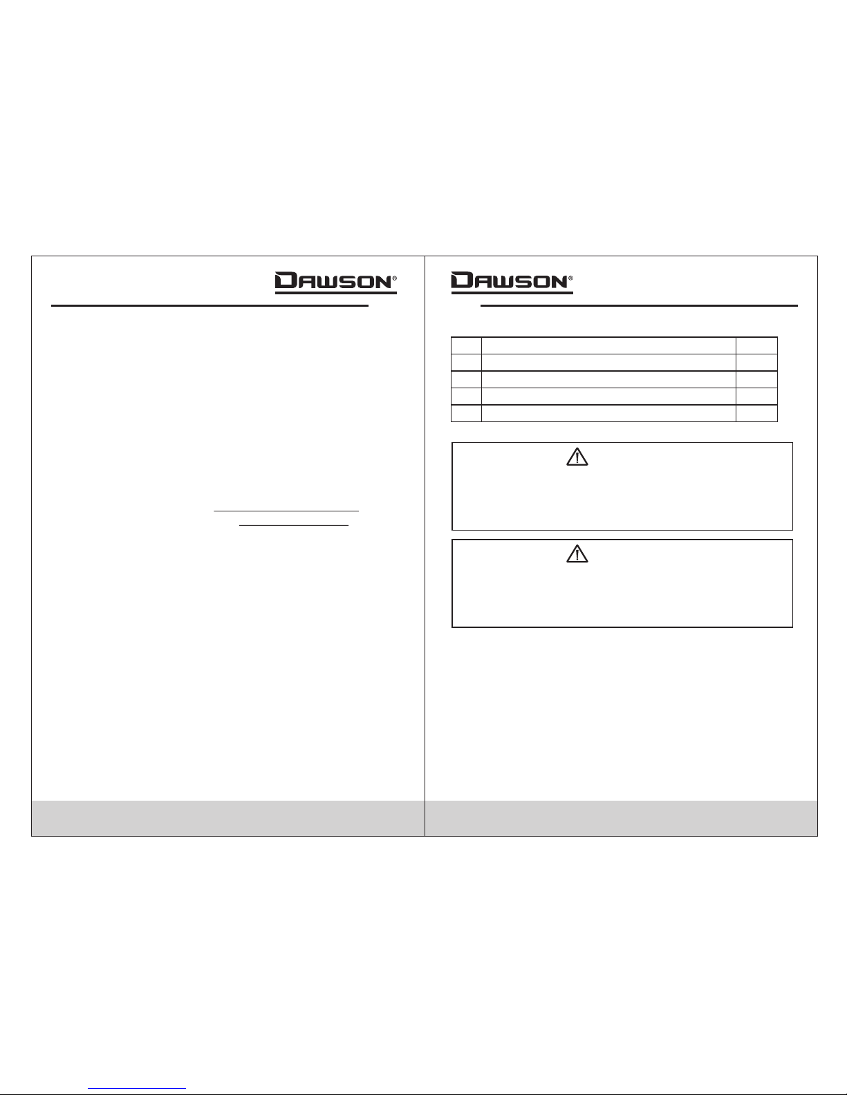
Accessories
Test Lea d
1.5V AA A Battery
Case
1
2
3
4
1 pcs
1 pcs
2 pcs
1 pcs
Safe ty Inform ation
To reduce t he risk of fi re, elect rical sho ck, produ ct
dama ge or perso nal injur y, pl ease foll ow the safe ty
inst ruction s describ ed in the use r ’s manua l. read
the ma nual befo re using th e meter.
Warning
To ensure s afe opera tion and li fe of the met er, do
not pl ace the met er in any env ironmen t with high
pres sure, hig h tempera ture, dus t, explos ive gas
or vap or.
Warning
1.Avoi d shaking , droppin g or any kind o f impacts w hen
usin g or transp orting th e meter.
2.To avo id electr ic shock or p ersonal i njury, repai rs or
serv icing not c overed in t his manua l should be
perf ormed onl y by qualif ied perso nnel.
3.Avoi d direct ex posure to s unlight t o ensure ex tended
life o f the meter.
4.Do n ot place me ter in a stro ng magnet ic field; t his may
caus e false rea dings.
5.Us e only the ba tteries i ndicate d in the Technica l Spec.
User ’s Manual
5
1 pcs
Alli gator Cli p & cable
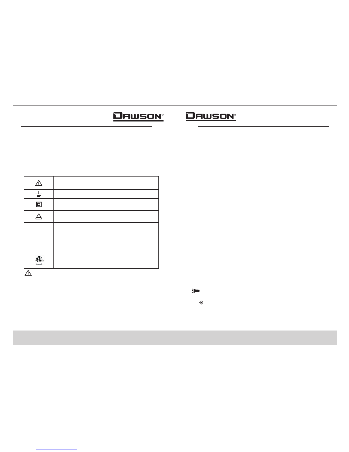
Impo rtant saf ety infor mation, p lease
refe r to the user ’s manual
Eart h ground
Indi cates com pliance w ith requi rements
for do uble insu lation
03 04
6.Avoi d exposin g batteri es to humid ity. Replace batteries
as soo n as the low ba ttery ind icator ap pears.
7.Pl ease keep t he origin al packin g for futur e shippin g
purp oses (ex. C alibrat ion)
8.Af ter openi ng the box, c heck for an y damage du ring
deli very.
Safe ty Symbol s
Impo rtant Saf ety Infor mation
• Repa ir or maint enance sh ould be imp lemente d by
trai ned perso nnel only.
Certification
CAT I :Thi s meter has m et IEC101 0-1 stand ard with an
over voltage c ategory ( CAT III) and pollution degree of 2.
The me ter comp i es to EMC req uiremen ts.
II
l
Fuse m ust be repl aced with r atings
spec ified in th e manual.
Conf orms to IEC 1010-1 st andards f or
over voltage i n categor y III insta llation s
with a p ollutio n degree of I I.
Comp lies with E uropean U nion (EU)
stan dards
CE
CATIII
Comp lies with U .S. and Can adian saf ety
stan dards.
• Neve r use the met er to measu re voltag es that mig ht
exce ed 600V DC/ AC above ea rth groun d in catego ry
III in stallat ions.
• Alway s be carefu l when work ing with vo ltage abo ve
60V DC o r 30VAC RMS. Kee p fingers b ehind the p robe
barr iers whil e measuri ng.
• Insp ect test le ads and pro bes for cra cks, brea ks or
craz es on the ins ulation b efore usi ng the mete r.
Introduction
Over view
The DD M350 is a por table pen -type dig ital mult imeter
feat uring DC/ AC voltag e and curre nt measur ements,
resi stance, c apacita nce, cont inuity, diod e testing ,
freq uency and d uty cycle , auto/ma nual rang e, workli ght,
and an L CD w/back light for e asy readi ng. The slim an d
ligh tweight d esign is mo bile and id eal for bot h
prof essiona ls and hobb yists.
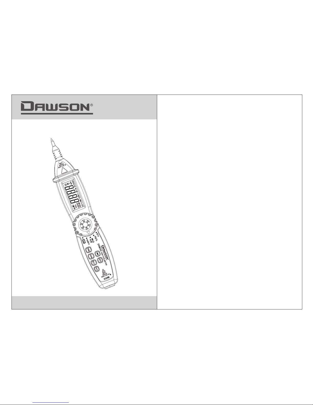
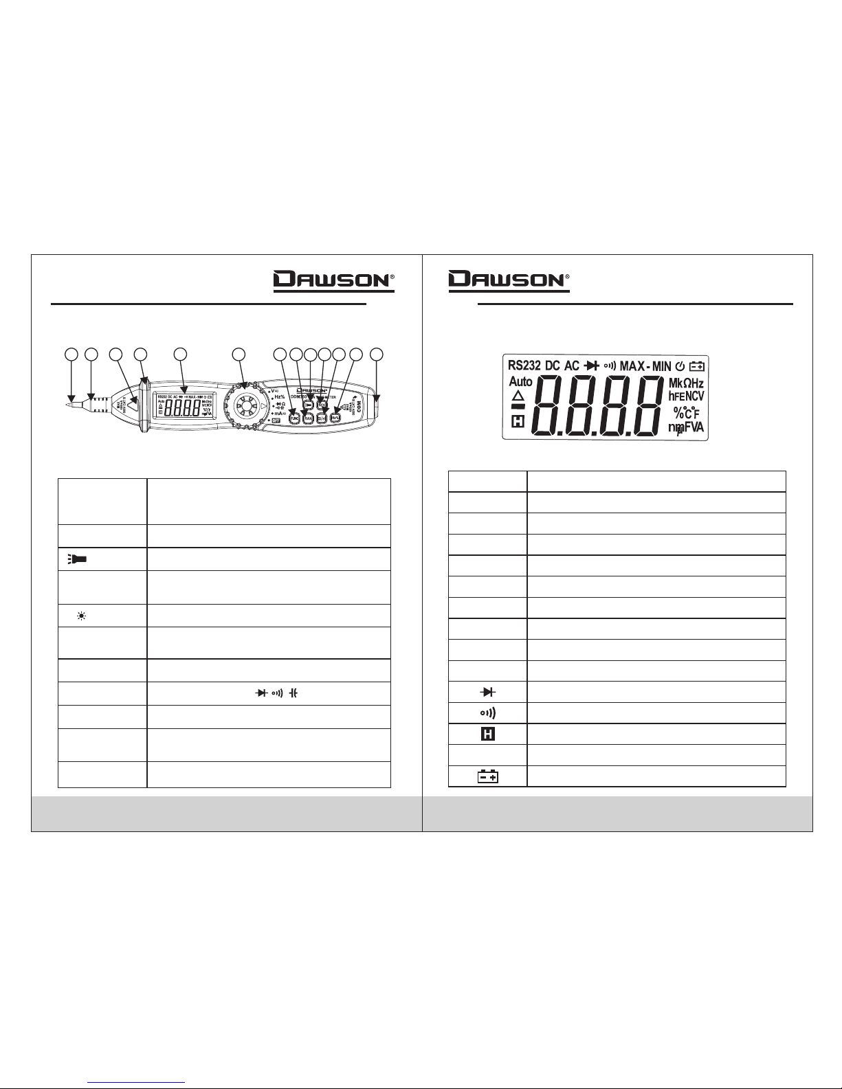
Figu res and Com ponents
Butt ons and Com ponents
1.Test P robe (+)
2.Pr obe Cap
3.NC V Indicat or
4.Pr otectiv e Ring
5.LC D Display
6.Ro tary Swit ch
7.FU NC (Funct ion) Butt on
8.RA N (Range) B utton
9. (Work l ight) But ton
10.N CV (Non-C ontact Vol tage) But ton
11.H/ (Ho ld/Back light) Bu tton
12.H z/% (Freq uency/D uty Cycle ) Button
13.C OM Jack (-)
03
05 06
Butt ons and Com ponents D escript ion
+ Inpu t for V/A/Ω / / / /Hz/ %
COM
Comm on termin al
Prob e Cap
Protective cap to be used when making
CAT III or above measurements
Protective Ring
Keep h and behin d the ring fo r safety
FUNC B utton
Swit ch betwee n AC/DC or bet ween
resi stance, c ontinui ty, diode or
capa citance
RAN Bu tton
Choo se auto or ma nual rang e
Butt on
Hold t o turn on the w ork light
Hold data reading/turn on/off backlight
NCV Bu tton
Hold t o activat e Non-Con tact Volta ge
meas urement
H/ But ton
Swit ch betwee n frequen cy/duty c ycle
func tions
Hz/% B utton
Sele ct differen t functio ns
Rota ry Switch
Prob e
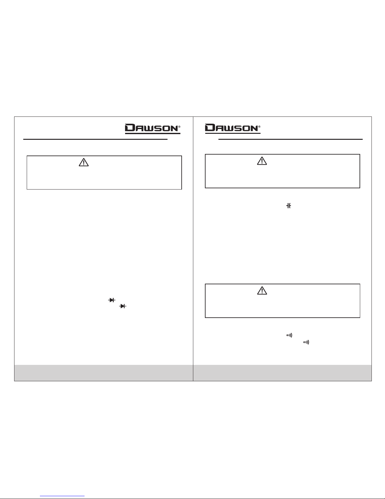
Disp lay Descr iption
°C°F
n,µ, m,k,M
nano , micro, mi lli, kilo , mega
Ω
Ohms ( resista nce)
F
Fara d (capaci tance)
A
V
Ampe re (curre nt)
Volt (v oltage)
Diod e
Buzz er
Data h old
AUTO
Auto r ange
Low ba ttery ind icator
AC
Alte rnating C urrent
DC Dire ct Curren t
%
Duty C ycle
Freq uency
Hz
Cels ius/Fah renheit
1
2
3
4
5
6
7
8
9
10
111213

07 0 8
Using the Meter
Prep aration
• Sele ct a functi on and a rang e for the ite m to be
meas ured usin g the rotar y switch an d “RAN” but ton if
nece ssary. In manu al range if t he range to b e measure d
is unk nown, sta rt with the h ighest ra nge.
• In man ual range , “OL” is dis played wh en overlo ad
occu rs. Choos e a higher ra nge.
• To perfo rm measur ement, fi rst conne ct the test l ead to
comm on (COM) in put then co nnect the p robe tip of t he
Mete r to the circ uit to be tes ted.
• If the b attery vo ltage is le ss than 2.4 V,“ ”is displayed.
Plea se change t he batter ies.
DC/A C Vol tage Meas urement
Use ca ution whe n measure ing high vo ltage cir cuits
to avo id electr ical shoc k and injur y. do n ot test
volt ages high er than dc/ ac 600v.
Warning
•
or hig her measu rements .
• Inse rt the blac k test lead o r lead with t est clip in t he
“COM ” jack.
• Set th e rotary sw itch to the “ V ”positi on.
• Pres s the “FUNC ” button to s witch bet ween DC and AC
meas urement s. Manual r ange can be s elected b y
pres sing the “R AN” butto n. Hold “RA N” to go back t o
Auto ra nge.
• Conn ect the pro be tip of the m eter and ti p of the test l ead
(or te st clip) ac ross the vo ltage sou rce or load .
• Read t he measur ement on th e display. The polarity of
the me ter ’s “+” probe will be indicated.
Make s ure the pro be cap is scr ewed on if ma king CAT III
NOTE :
At sma ll voltag e ranges th e meter may s how unste ady
read ings when t est leads a re not conn ected to th e circuit ,
this i s normal be cause of th e sensiti vity of the m eter.
When t he meter is c onnecte d to the circ uit, true r eadings
will b e display ed.
DC/A C Current M easurem ent
Use ca ution whe n measure ing high vo ltage cir cuits
to avo id electr ical shoc k and injur y. do n ot test
volt ages high er than dc/ ac 600v.
Warning
• Make s ure the pro be cap is scr ewed on if ma king CAT III
or hig her measu rements .
• Inse rt the blac k test lead o r lead with t est clip in t he
“COM ” jack.
• Set th e rotary sw itch to the “ mA ”posi tion.
• Pres s the “FUNC ” button to s witch bet ween DC and AC
meas urement s. Manual r ange can be s elected b y
pres sing the “R AN” butto n. Hold “RA N” to go back t o
Auto ra nge.
• Conn ect the pro be tip of the m eter and ti p of the test
lead ( or test cli p) across t he power so urce or loa d.
• Read t he measur ement on th e display. The polarity of
the me ter ’s “+” probe will be indicated.
09 10
Resi stance Me asureme nt
To avoid el ectrica l shock and i njury, power off t he
circ uit and dis charge th e capacit ance befo re
meas uring res istance .
Warning
• Inse rt the blac k test lead o r lead with t est clip in t he
“COM ” jack.
• Set th e rotary sw itch to the “ ” positi on. Manua l range
can be c hosen by pr essing th e “RAN” but ton. Hold
“RAN ” to go back to Au to range.
• Conn ect the pro be tip of the m eter and ti p of the test
lead ( or test cli p) across t he resist ance or cir cuit unde r
meas urement a nd read the m easured v alue on the
disp lay.
Ω
NOTE :
•
read ing if the me asured re sistanc e is above 1M Ω.
• When t he input is n ot connec ted (i.e. a n open circ uit)
“OL” w ill be disp layed.
The me ter may tak e a few secon ds to reach s teady
Diod e Tes t
•
• Set th e rotary sw itch to the “ ” positio n. Press “F UNC”
to cho ose diode m easurem ent; “ ”is di splayed .
• Conn ect the pro be tip of the m eter and ti p of the test
lead ( or test cli p) across t he diode un der measu rement
and re ad the meas ured valu e on the disp lay.
Inse rt the blac k test lead o r test clip i n the “COM” j ack.
NOTE :
The Me ter shows t he forwar d voltage d rop. If the l ead
conn ection is r eversed , “OL” is dis played.
Capa citance M easurem ent
To avoid el ectrica l shock and i njury, power off t he
circ uit and dis charge th e capacit ance befo re
meas uring cap acitacn e.
Warning
• Inse rt the blac k test lead o r lead with t est clip in t he
“COM ” jack.
• Set th e rotary sw itch to the “ ”
• posi tion.Pr ess “FUNC ” twice to ch oose capa citance
meas urement .There is n o manual ra nge avail able in
capa citance m ode.
• Conn ect the pro be tip of the m eter and ti p of the test l ead
(or te st clip) ac ross the ca pacitan ce or circu it under
meas urement a nd read the m easured v alue on the
disp lay.
NOTE :
The me ter may tak e a few secon ds to reach s teadyea ding
when m aking hig h capacit ance meas urement s.
Cont inuity
To avoid el ectrica l shock and i njury pow er off the
circ uit and dis charge th e capacit ance befo re
meas uring con tinuity.
Warning
•
“COM ” jack.
• Set th e rotary sw itch to the “ ” positio n. Press “F UNC”
3 time s to choose c ontinui ty test; “ ”i s display ed.
• Conn ect leads t o the circu it termin als.
• If con tinuity e xists (i. e. resist ance is les s than 50Ω) , the
buil t-in buzz er will sou nd.
Inse rt the blac k test lead o r lead with t est clip in t he
11 12
Data H old
• If the r esult is an o pen circu it (or the me asured ci rcuit
resi stance is h igher tha n 200Ω) “0L ” is displa yed.
Freq uency/D uty Cycle
Use ca ution whe n measure ing high vo ltage cir cuits
to avo id electr ical shoc k and injur y. do n ot test
volt ages high er than dc/ ac 600v.
Warning
• Make s ure the pro be cap is scr ewed on if ma king CAT III
or hig her measu rements .
• Inse rt the blac k test lead o r test clip i n the “ jack.
• Set th e rotary sw itch to the “ Hz%” posi tion; “Hz ” is
disp layed.
• Conn ect the pro be tip of the m eter and ti p of the test
lead ( or test cli p) across t he source o r load for
meas urement a nd read the m easured f requenc y on the
disp lay.
• Pres s “Hz%” to sw itch to dut y cycle mea suremen t; “%”
is dis played.
• Conn ect the pro be tip of the m eter and ti p of the test
lead ( or test cli p) across t he source o r load for
meas urement a nd read the m easured d uty cycle o n
the di splay.
• Alte rnative ly, while in AC vol tage or AC cur rent mode s,
pres sing the “H z%” butto n will swit ch to frequ ency
mode .Press th e button ag ain to swit ch to duty cy cle.
Pres s the butto n a third tim e to return t o voltage /curren t
mode .
COM”
To hold a re ading, pr ess the“ / ”b utton and t he curren t
read ing will be h eld on the di splay. Press t he button a gain
to ret urn to norm al readin g.
Back light
• Hold t he“ / ”butt on for two se conds to tu rn on
back light. The ba cklight w ill go off automatically after
10 sec onds.
• Hold t he“ / ”butt on again to m anual tur n off the
back light.
Work lig ht
Whil e the meter i s on in any pos ition, ho ld the “ ”
butt on to turn on t he work lig ht.Use th is in areas t hat are
poor ly illumi nated to ma ke measur ements ea sier.
NCV (N on-Cont act Voltage)
Whil e the meter i s on in any pos ition, ho ld the “NCV ”
butt on to turn ch eck for the p resence o f voltage . Move
the to p of the mete r toward th e voltage s ource and i f the
volt age detec ted is >110VAC, the meter will beep and
the NC V indicat or will fla sh.
NOTE :
Do not r ely solel y on NCV dete ction to de termine t he
pres ence of vol tage in a con ductor.S ocket des ign,
insu lation, i nterfer ence, etc . can affect de tection .
Auto O ff
When n ot in use, th e Meter wil l automat ically tu rn off after
appr ox. 15 minu tes. After a uto off, pres s “FUNC” to t urn
the po wer back on . Th e Meter wil l beep 5 time s 1 minute
befo re and a long b eep right a s it turns off.
Hold t he “FUNC” b utton whi le turnin g on the mete r to
disa ble auto off.

13 14
Specifications
Gene ral Speci ficatio ns
Envi ronment C onditio ns
600V C AT. III
Poll ution Deg ree
2
Maxi mum Opera ting Altit ude
7000 F t (2000m)
Oper ating Tempera ture
0~40 °C, 32°F~ 122°F
(<80 % RH, <10℃
non- condens ing)
Disp lay
20mm L CD
Max. ValueDisp lay
3999 ( 3 3/4 digit d isplay)
Pola rity Indi cation:
“-”i ndicate s negativ e
pola rity.
Over range Ind ication
Disp lay “OL .show s ”
Samp ling Time
appr ox. 0.4 sec ond
Unit D isplay
Disp lays func tion and
meas ured valu e.
Low Ba ttery Ind ication “ ”dis played
Fuse P rotecti on:
FF40 0mA/600 V
Stor age Temperatu re
-10~ 50 °C, 14°F ~122°F
(<70 % RH, batte ry
remo ved)
Max. Vo ltage Bet ween
Termin als And Eart h Ground
600V D C or AC
Auto Ranges and Manual Range
Auto p ower off time
15 min .
Powe r Supply
1.5V ×2 AAA batter y.
Dime nsion
8.9x 1.6x1.4 i n.
(227 ×40×35m m)
Weight
appr ox. 4.48o z (127g)
incl uding bat tery sss
Technic al Specif ication s
DC vol tage
Reso lution
0.1mV
Accu racy
400mV
0.001V
0.01V
0.1V
1V
4V
40V
400V
600V
±(0.5% reading + 3 digits)
Rang e
-
-
-
Inpu t Impedan ce: 10MΩ
Over load Prot ection: 4 00mV rang e: 250V DC or AC r ms
4V to 60 0V ranges : DC 600V or AC 60 0V rms
Max. I nput Volta ge: 600V DC

Func tion
Rang e
If res istance i s lower tha n 50Ω , the bu ilt in
buzz er will sou nd.
- - Open c ircuit vo ltage: 1. 0V
Over load Prot ection: 2 50V DC or RMS AC
Reso lution
Func tion
Rang e
Disp lays diod e forward v oltage
0.001V
-
-
-
Forw ard DC Curr ent: 1mA
Reve rsed DC Volt age: 3.2V
Over load Prot ection: 2 50V DC or RMS AC
Resi stance
Reso lution
0.1Ω
Accu racy
400Ω
0.001kΩ
0.01kΩ
0.1kΩ
4kΩ
40kΩ
400kΩ
4MΩ
±(1.0% reading + 3 digits)
Rang e
±(1.0% reading + 5 digits)
- Open c ircuit vo ltage:1 .0V
- Over load prot ection: 2 50V DC or AC (RM S)
40MΩ 0.01MΩ
0.001MΩ
±(1.0% reading + 1 digits)
15 16
AC voltage
Reso lution
0.1mV
Accu racy
±(0.8% reading + 3 digits)
400mV
0.001V
0.01V
0.1V
1V
4V
40V
400V
600V
±(0.8% reading + 3 digits)
Rang e
±(1.0% reading + 3 digits)
- Inpu t Impedan ce: 10MΩ
Over load Prot ection: 4 00mV rang e: 250V DC or AC r ms
4V to 60 0V ranges : DC 600V or AC 60 0V rms.
-
- Freq uency ran ge: 40 to 400 hz
- Resp onse: True R MS
- Maxi mum input v oltage: 6 00V AC rms
Reso lution
0.01 mA
Accu racy
±(1.5% reading + 3 digits)
40mA
0 1 mA.400mA
Rang e
- Over load prot ection: r esettab le fuse 400 mA/600V
DC Cur rent
AC Cur rent
Reso lution
0.01 mA
Accu racy
±(2.0% reading + 3 digits)
40mA
0 1 mA.400mA
Rang e
-
- Freq uency Ran ge: 40 to 400 Hz
- Resp onse: True R MS
Over load prot ection: r esettab le fuse 400 mA/600V
Diod e
Cont inuity
17 1 8
- Over load Prot ection: 2 50V DC or AC RMS
Func tion
±(0.5% reading + 3 digits)
Hz
%
Rang e
0-10MHz
1-99 %
Freq uency/D uty Cycle
Accu racy
±(3.0% reading + 3 digits)
Capa citance
Reso lution
0.001nF
Accu racy
4nF
0.01nF
0.1nF
1nF
40nF
400nF
4µF
±(4.0% reading + 10 digits)
Rang e
0.01µF
40µF
0.1µF
400µF
1µF
4mF
0.01µF
40mF
- Over load Prot ection: 2 50V DC or AC RMS
Main tenance a nd Repair
Repa ir
Plea se follow t hese step s closely i f the meter i s not
func tioning p roperly :
• Chec k the batte ries; rep lace with n ew batter ies if low
batt ery indic ator “ ”app ears.
• Foll ow the user ’s manual to confirm all procedures.
• Befo re sendin g the meter b ack for rep air, inclu de a
desc ription o f the probl ems encou ntered. R emove
batt eries and p ack the met er well to av oid damag e
duri ng delive ry; Dawso n does not co ver damag e due to
deli very.
• Repa ir or servi ce not cove red in this m anual sho uld be
perf ormed onl y by the auth orized se rvice cen ter or
qual ified per sonnel.
Test Lead s Replace ment
Repl ace the tes t leads wit h identic al or compa tible
lead s. lead spe c:600V 10 A.
Warning
Repl ace new lea ds if the cur rent lead s are worn or
dama ged.
Repl acing the b atterie s
Foll ow these st eps to repl ace the bat teries:
• Turn off the meter.
• Loos en the batt ery cover a nd remove t he cover fr om
the ca se’s bottom .
• Remo ve the batt eries and r eplace th em with new o nes.
• Re-a ttach the b attery co ver to the ca se’s bottom a nd
tigh ten the scr ew.

19
Cont act Dawso n
Daws on Tools , Inc.
1142 S. Dia mond Bar Bl vd., #858
Diam ond Bar, CA 9 1765
Phon e:
www.D awsonTool s,com
(310 ) 728-622 0
Feat ures
• True RMS
• LCD Di splay
• Auto a nd Manual R ange
• Auto P ower Off
• Diod e Test
• Audi ble Conti nuity
• Non- Contact Vo ltage Det ection
• Work lig ht
• Back light
• Data H old
• Low Ba ttery Ind icator
00-05-3544
 Loading...