


Dawson DAN120
Analog Multimeter
User’s Manual

1
TABLE OF CONTENTS
LIMITED WARRANTY AND LIMITATION OF
LIABILITY ..................................................... 3
Out of the Box ............................................. 3
Accessories ................................................. 4
Safety Information ...................................... 6
Certification ............................................... 6
INTRODUCTION ........................................... 7
Overview ..................................................... 7
Figures and Components ............................ 7
USING THE METER ....................................... 8
Preparation ................................................ 8
Reading the Scale ....................................... 9
DC/AC Voltage Measurement ................. 10
Common AC Voltage Measurements ....... 11
DC Current Measurement (mA) ............... 12
Common DC mA Current Measurements. 12
DC 10A Measurement .............................. 14
Resistance/Continuity Measurement ....... 14
Extension Cords Continuity Test ............... 15

2
Fuses Test ................................................. 16
Switches .................................................... 16
Transistor Gain Measurement (dB) .......... 17
1.5V and 9V Battery Test .......................... 18
SPECIFICATIONS ........................................ 18
General Specification ................................ 18
MAINTENANCE AND REPAIR ..................... 19
Repair ....................................................... 19
Replacing Batteries ................................... 20
Replacing Fuses ........................................ 20
CONTACT DAWSON ................................... 21

3
LIMITED WARRANTY AND
LIMITATION OF LIABILITY
This instrument from Dawson Tools Inc. will be free from defects
in workmanship and material for three years from the date of
original purchase. This warranty does not cover defects resulting
from damage caused by the user such as drops, neglect, misuse,
unauthorized alteration, usage outside of specified conditions,
contamination, or improper repair/maintenance. To receive
service on the instrument if it becomes necessary during the
warranty period, contact your nearest Dawson authorized service
center at (800) 898-6991 or visit www.DawsonTools.com to
obtain a return authorization (within the US only). A return
authorization is necessary before returning any instrument to
Dawson; no service will be provided without a return
authorization. The user is responsible for properly packing the
unit and charges such as shipping, freight and insurance charges.
The extent of Dawson's liability is limited solely to the
repair/replacement of the instrument. The above warranty in its
entirety is inclusive and no other warranties, written or oral, are
expressed or implied.
Out of the Box
Check the Meter and accessories thoroughly before using
the Meter. Contact your local distributor if the Meter or
any components are damaged or malfunction.
4
Accessories
Test Leads
1 pair
1.5V AA Battery
1pc
Safety Information
WARNING
TO REDUCE THE RISK OF FIRE, ELECTRICAL SHOCK,
PRODUCT DAMAGE OR PERSONAL INJURY, PLEASE
FOLLOW THE SAFETY INSTRUCTIONS DESCRIBED IN THE
USER MANUAL. READ THE USER MANUALS BEFORE
USING THE METER.
Avoid shaking, dropping or any kind of
impacts when using or transporting the Meter.
To avoid electric shock or personal injury,
repairs or servicing not covered in this manual
WARNING
TO ENSURE SAFE OPERATION AND LIFE OF THE METER,
DO NOT PLACE THE METER IN ANY ENVIRONMENT WITH
HIGH PRESSURE, HIGH TEMPERATURE, DUST, EXPLOSIVE
GAS OR VAPOR.
5
should be performed only by qualified
personnel.
Avoid direct exposure to sunlight to ensure
extended life of the Meter.
Do not place Meter in a strong magnetic field;
this may cause false readings.
Use only the batteries indicated in the
Technical Spec.
Avoid exposing batteries to humidity. Replace
batteries as soon as the low battery indicator
appears.
Please keep the original packing for future
shipping purposes (ex. Calibration)
After opening the box, check for any damage
during delivery.
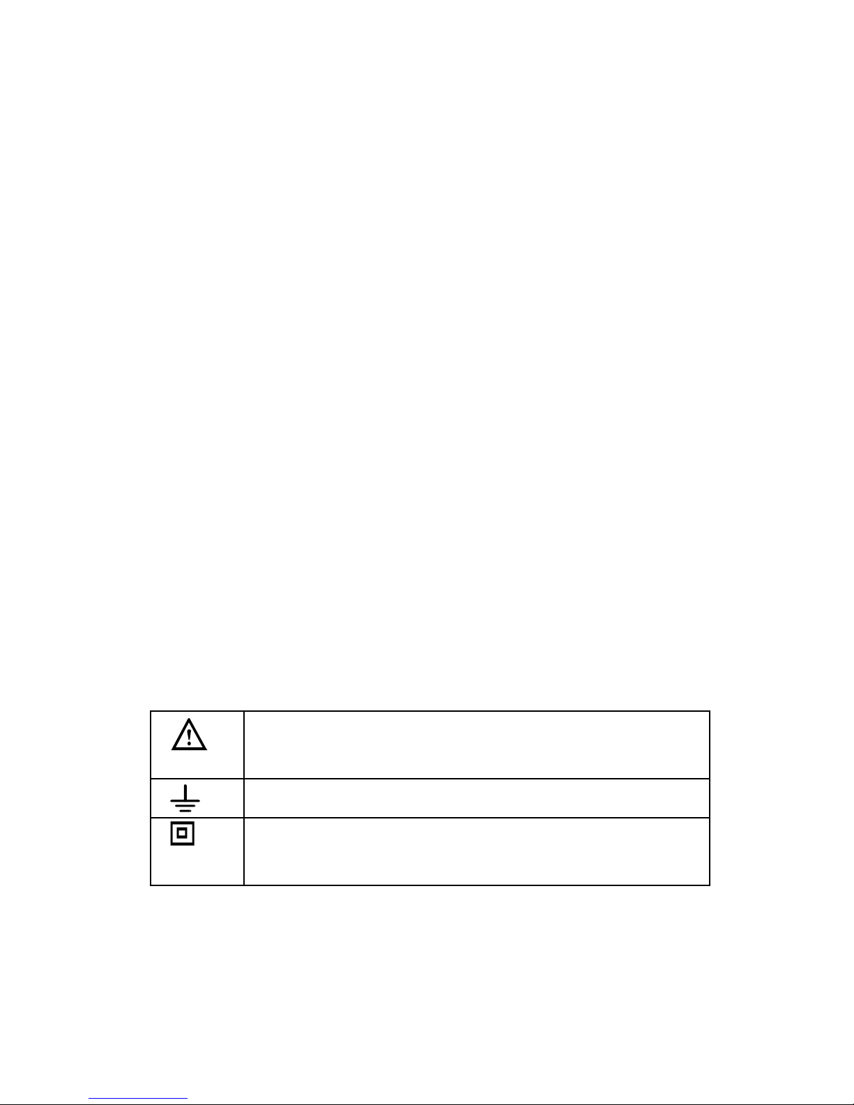
Safety Symbols on the Meter
Important safety information, please refers
to the user manual
Earth ground
Indicates compliance with requirements for
double insulation

6
Important Safety Information
Never use the Meter to measure voltages that
might exceed 1000V DC/AC above earth
ground.
Always be careful when working with voltages
above 60V DC or 30V AC RMS. Keep fingers
behind the probe barriers while measuring.
Never connect the Meter leads across a
voltage source while the rotary switch is in
the resistance, diode or continuity mode.
Doing so can damage the Meter.
Inspect test leads and probes for cracks,
breaks or crazes on the insulation before
using the Meter.
Repair or maintenance should be
implemented by trained personnel.
Certification
CAT II: This meter has meet IEC1010-1
standard with an overvoltage category (10
00V CAT II) and pollution degree 2.
The Meter is compiled to EMC
requirements.

7
Introduction
Overview
The DAN120 is a compact analog multimeter featuring
large analog scale. Functions include AC/DC voltage,
AC/DC current measurement, resistance measurement
and battery test. This DAN120 meter is ideal for both
professional and hobbyists.
Figures and Components
Front Panel

8
Using the Meter
Preparation
Fully plug the test leads into the input jacks. Red lead to
“VΩA+” input and black lead to “COM-“ input.
Calibration of the scale is needed before making
measurement. Use a small size flat tip screwdriver to
adjust the black knob located in the center of the Meter,
next to the Dawson logo. The needle on the scale should
align with “0” on the left side of the scale.
The “ ” symbol next to the input lead
shows that the input voltage or current should
not exceed the specified value in order to
protect the internal circuit from damage.
Turn the rotary switch to the required
function and range to be measured.
Choose the highest range when the value to
be measured is unknown.
When making connection, connect the
common test lead first and then the powered
test lead.
Remove the charged test lead first when
disconnecting.

9
Reading the Scale
General
Make sure to align the needle with the scale.
Resistance (Ohms - Ω)
Use the top scale (Green) to read resistance.
If the meter is set to X10, multiply the resistance value by
10, and in x1K multiply the resistance value by 1000.
DC Voltage (V DC)
Use the middle scale (Black). To read of the
measurement, first match the dial range setting to the
highest number on the scale to find out the according
scale.

10
NOTE:
For 2.5V range measurement, use the scale of
250V and divide by 100.
For 1000V range measurement, use the scale
of 10V and multiply by 100.
AC Voltage (V AC)
Use the same numbers and procedures used for DC
voltage measurement.
DC Current (mA)
Use the same scale (Black) and procedures as used for
the DC voltage setting.
Decibel Gain (dB)
Use the scale marked dB to read decibels for transistor
gain. Use the chart at the right of the scale for proper
conversion.
DC/AC Voltage Measurement
Plug the test leads in to input jacks.
Use rotary switch to select DCV or ACV and the
proper range (0~2.5 DC only, 0~10V, 0~50V, 0~250V
or 0~1000V). Choose the highest range when the
value to be measured is unknown.

11
Connect the test leads to the circuit in series, that is,
to let the current of the circuit to pass the Meter
through test leads. If the needle deflects to the left,
reverse the leads connection.
Read of the scale as described in Reading the Scale.
Common AC Voltage Measurements
Wall Receptacles
If the receptacle is controlled by a switch, make sure the
switch is ON. Set the rotary switch to 250 ACV. Touch the
red test lead to the “hot” and black to the “neutral” slots
of the receptacle (see fig. 3A). The needle indicator
should read 120V AC on the 0-250 scale. To test for
proper grounding of the receptacle, touch the red test
lead to the “hot” (narrow) side of the receptacle, and the
black test lead to the ground slot. The meter should read
120V AC as before.

12
DC Current Measurement (mA)
Plug the test leads in to input jacks.
Connect the test lead to the target, red to positive
and black to negative terminals.
Read of the scale as described in Reading the Scale.
NOTE:
For 5mA Range, use the 0-10 scale and then
multiply by 0.5mA
For 500mA Range, use the 0-250 scale and
multiply by 2mA
Common DC mA Current Measurements
WARNING
DO NOT APPLY VOLTAGE TEST WHEN ROTARY SWITCH
IS IN CURRENT MODE
WARNING
DO NOT APPLY VOLTAGE TEST TO THE TEST LEADS
WHEN ROTARY SWITCH IS IN CURRENT MODE

13
It is important to point out that milliamps can also be
expressed as thousandths of an Ampere; therefore 500
milliamps is 500 thousandths of one Amp. The 500mA
function of your multimeter is commonly used by
electronics repair technicians and hobbyists to
troubleshoot various low voltage circuits. Although not
normally used for electrical troubleshooting around
house, this function can be used to measure the milliamperage draw of household items such as flashlights
and other battery operated devices that do not draw
more than 500 mA. In fig. 2 the red (+) test lead is
hooked up to the (+) terminal of the lantern battery
while the black (-) test lead is hooked up to the bulb. The
meter will indicate the milli-amperage draw when the
flashlight switch is thrown in the ON position.

14
DC 10A Measurement
A separate input jack is provided for measurement of DC
current up to 10A. Maximum measuring time is 15
seconds with a 30 second interval between tests. Rotate
the switch to “10A” position and use the “DC 10A” input.
Use the 0~10 scale for reading.
Resistance/Continuity Measurement
WARNING
DO NOT APPLY VOLTAGE TEST WHEN ROTARY SWITCH
IS IN CURRENT MODE
WARNING
DO NOT APPLY VOLTAGE OR CURRENT TEST WHEN
ROTARY SWITCH IS IN RESISTANCE MODE
WARNING
POWER OFF THE CIRCUIT

15
Plug the test leads into input jacks.
Rotate the switch to “Ohm” mode.
Choose the highest range (x1K) when the value to
be measured is unknown.
Connect the test lead to the target, polarity can be
ignored.
For Resistance read of the scale (Green) as
described in Reading the Scale.
For Continuity test, turn the rotary switch to “ ”.
Connect the leads to the circuit. If the circuit is well
connected, the Meter will buzz to indicate good
continuity.
NOTE:
When switching between resistance mode and other
modes, always calibrate the needle to zero before
making measurement.
Extension Cords Continuity Test
Unplug the cord from two sides. Set the rotary switch to
the ohm x1K position. Touch one of the test leads to one
of the metal prong ends of the cord, insert the other test
lead in either one of the receptacle slots on the other
end of the cord. Make sure the test lead is making
contact with the slot. Test both slots with the test lead,
making sure in both cases that the leads are well

16
connected to the slot. If none of the tests appear to have
0 ohm resistance, the continuity test fails. Fig.4
Fuses Test
Remove the fuse from the appliance. Touch each end of
fuse (fig.5) with the test leads and perform the continuity
test. For plug type fuses, touch the test leads at the
bottom and the threaded metal contact (fig.6).
Switches
Remove the switch from any power source. Turn the
switch to ON position and touch the test leads to the
switch terminals (fig. 7). If the switch is good, the needle

17
indictor will move to ~0 ohm. On other switches such as
three-way light switches or double pole double throw
(ON-OFF-ON) switches, each ON position will need to be
tested. Alternate the test leads between the switch
terminals to determine which two terminals control the
ON position.
Transistor Gain Measurement (dB)
To measure the gain of a transistor:
Plug the test leads into the input jacks.
Set the rotary switch to any one of the AC voltage
ranges and read the decibel measurement on the
bottom (red) scale.
Compute the actual decibel conversion based on
the chart located at the bottom right of the
faceplate.

18
NOTE:
Circuit impedance must be at least 600 ohms.
0 decibels = 1 milliwatt.
1.5V and 9V Battery Test
To check if the battery is in good or bad condition,
switch the rotary switch to “1.5V AA” or “9V” on
the right side according to the battery type.
Connect the red lead (+) to the (+) side of battery
and black lead (-) to the (-) side.
Read the result, REPLACE or GOOD, from the
bottom of the scale.
Specifications
General Specification
Ranges: 19 measuring modes
DC Voltage: 2.5,10,50,250,1000 Volts
AC Voltage: 10,50,250,1000 Volts
DC Current: 5,50,500mA and 10A
Resistance : Rx1, Rx10, Rx1K (resistance indicated
multiplied by 1, 10 and 1000) ohms
AC voltage range:-8dB to +62dB
Accuracy:
DC voltage, mA = ±4% full scale of range

19
AC voltage = ±5 % full scale of range
Resistance = ±4% arc of scale length
Operating altitude: max. 2000 meters (7000 ft.)
Display: Analog display
Fuse: F500mA/250V Φ 5.2x20mm
F10A/250V Φ 5.2x20mm
Power Supply : 1.5V×1 AA batteries
Test Lead: CE CATII 1000V 10A
Operating Temperature: 18°C to 25°C (64°F to 77°F)
Dimension: 149×97×43mm (5.8x3.8x1.7 in.)
Weight: approximate 250g (9.8oz) including
batteries
Maintenance and Repair
Repair
Please follow the steps closely if the Meter is not
functioning properly:
Check batteries; replace if necessary
Follow User’s Manual to confirm all
procedures.
Before sending Meter back for repair, include
a description of the problems encountered.
Remove batteries and pack Meter well to
avoid damage in delivery, Dawson does not
cover damage due to delivery.

20
Repair or service not covered in this manual
should be performed only by the authorized
service center or qualified personnel.
Replacing Batteries
Follow these steps to replace batteries:
Turn off the Meter.
Loosen the back cover and remove from case.
Remove batteries and replace with new batteries.
Re-attach back cover and tighten screw.
Replacing Fuses
Fuses rarely need replacement. Almost all blows are the
result of operation error.
Loosen the back cover like in the Replacing
Batteries.
Replace the blown fuse with one at the
specified rating described in Technical
Specification.
Re-attach back cover and tighten screw.

21
Contact Dawson
Dawson Tools, Inc.
1142 S. Diamond Bar Blvd., #858
Diamond Bar, CA 91765
Phone: (310) 728-6220
www.DawsonTools,com
Do not recycle
 Loading...