

Page 1
DZA50
USER’S MANUAL
AC LINE SPLITTER
01 02
1. SAFETY INFORMATION
Users must read and follow all safety instructions
before using this unit in order to prevent personal
injury or damage to the unit.
1.Please check that there is no damage to the unit or
insulation.
2.Input should not exceed more than AC 250V, 15A in order
to avoid electrical shock or danger.
3.Don’t open the back cover to avoid damaging the insulation.
4.Turn off power first before removing the test leads from
the voltage test jacks.
2. GENERAL DESCRIPTION
This instrument is a special accessory for clamp meters
which can be used to measure current conveniently without
breaking the insulation on equipment’s power line. It can
also be used to test the equipment’s working voltage using
a multimeter. It’s an essential tool for safely taking electrical
measurements with little damage to the equipment under
test. Its quality construction and easy to use design is built
according to IEC61010 standards with an overvoltage
category of 250V CAT III.
3. FEATURES
1Safety standard conforms to IEC61010.
2.Maximum input: AC 250V, 15A.
3.Operating temperature: 0~40°C;
Humidity: ≤90%
4.Storage temperature: 10~50°C;
Humidity: ≤90%
5.Dimensions: 161×57×31 mm
6.Weight: approx. 106g
7.Accessories: user’s manual
.
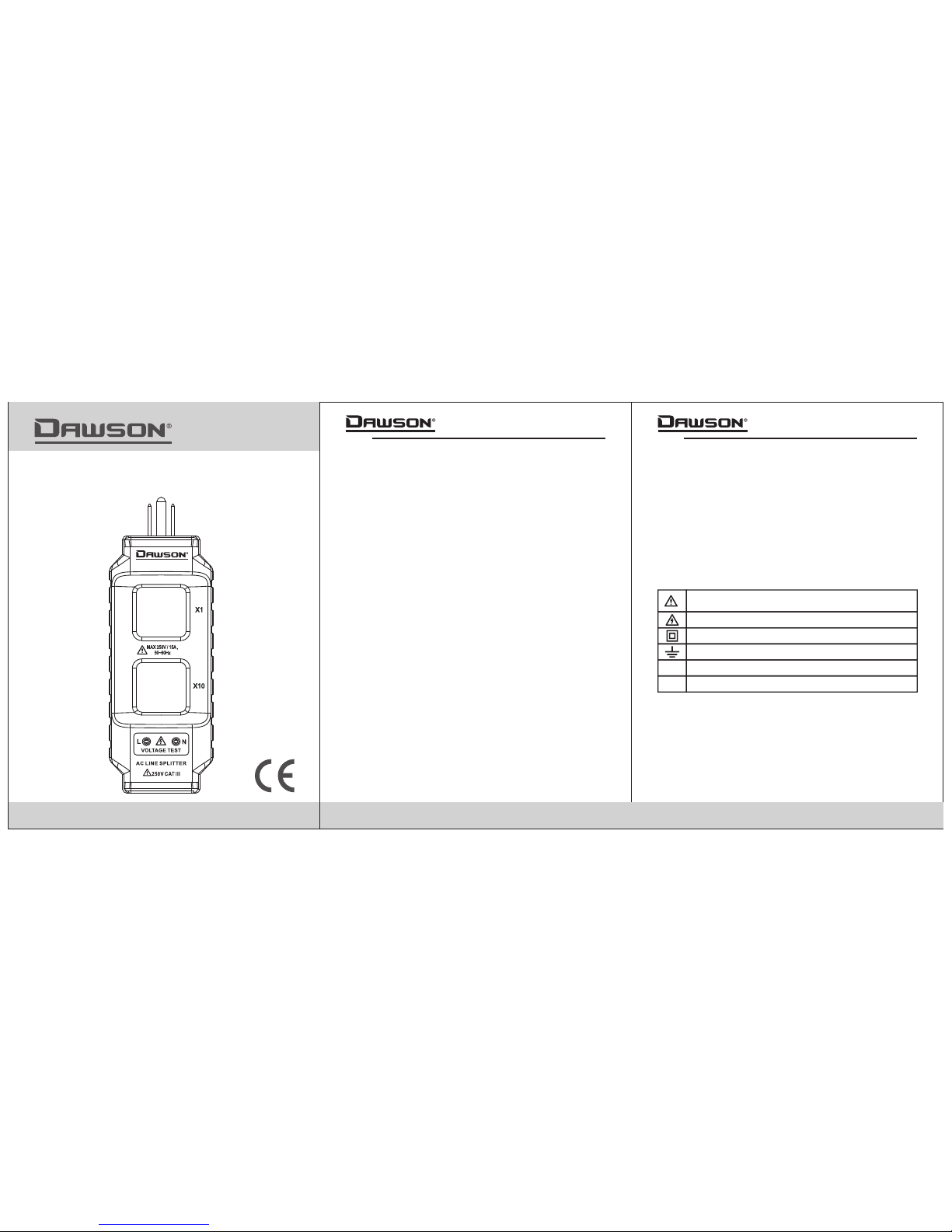
4. SAFETY SYMBOLS
L
N
Important safety information:refer to the user’s
manual
Dangerous voltage may be present
Double insulation
Earth ground
Live wire connection for voltage test
Neutral wire connection for voltage test
DZA50
Page 2
05
00-05-3606
0403
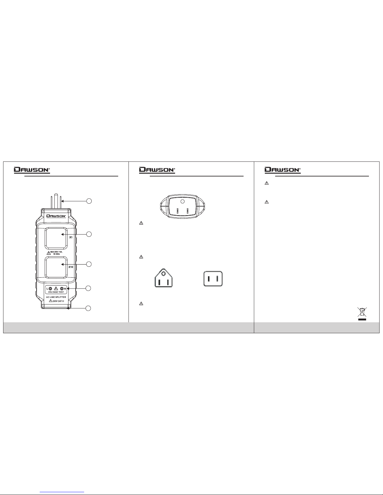
5. FRONT PANEL
5.1 Front panel description
1. Power plug:
This is a standard plug as shown below:
Overload protection: AC 250V, 15A
2. “X1” current terminal:
Tests actual working current.
3. “X10” current terminal:
Tests working current x10.
4. Voltage test input sockets:
Insert test lead probes to measure voltage.
5. Input socket:
Maximum input: AC 250V, 15A.
This socket is suitable for two standard plug configurations.
These configurations are shown in the figure below:
6. OPERATING INSTRUCTIONS
6.1 Current testing
Each terminal of the splitter will give a different current
reading:
X1 terminal for normal current load.
X10 terminal for 10 times the normal current load.
The error of the clamp meter itself will influence the
testing degree of accuracy.
6.2 Voltage testing
1 Connect the power plug to an outlet.
2. Plug the device to be measured into the input socket.
3. Connect the test leads of your multimeter to the voltage
test sockets and put the meter in AC voltage mode to
measure the voltage of the connected device.
.
6.3 Power testing
1 Connect the power plug to an outlet.
2. Plug the device to be measured into the input socket.
3. Connect the test leads of your multimeter to the voltage
test sockets and put the meter in AC voltage mode to
measure the voltage of the connected device.
4. Use a clamp meter and clamp the desired current terminal
of the line splitter for measurement.
5. Calculate the power of the connected device using the
following formula:
Power = voltage x current
.
Maximum input is: AC 250V, 15A.
1. Connect the power plug to an outlet.
2. Plug the device to be measured into the input socket.
3. Use a clamp meter and clamp the desired current terminal
of the line splitter for measurement.
1
2
3
4
5
DZA50
 Loading...