

Dawson DCT220 User Manual
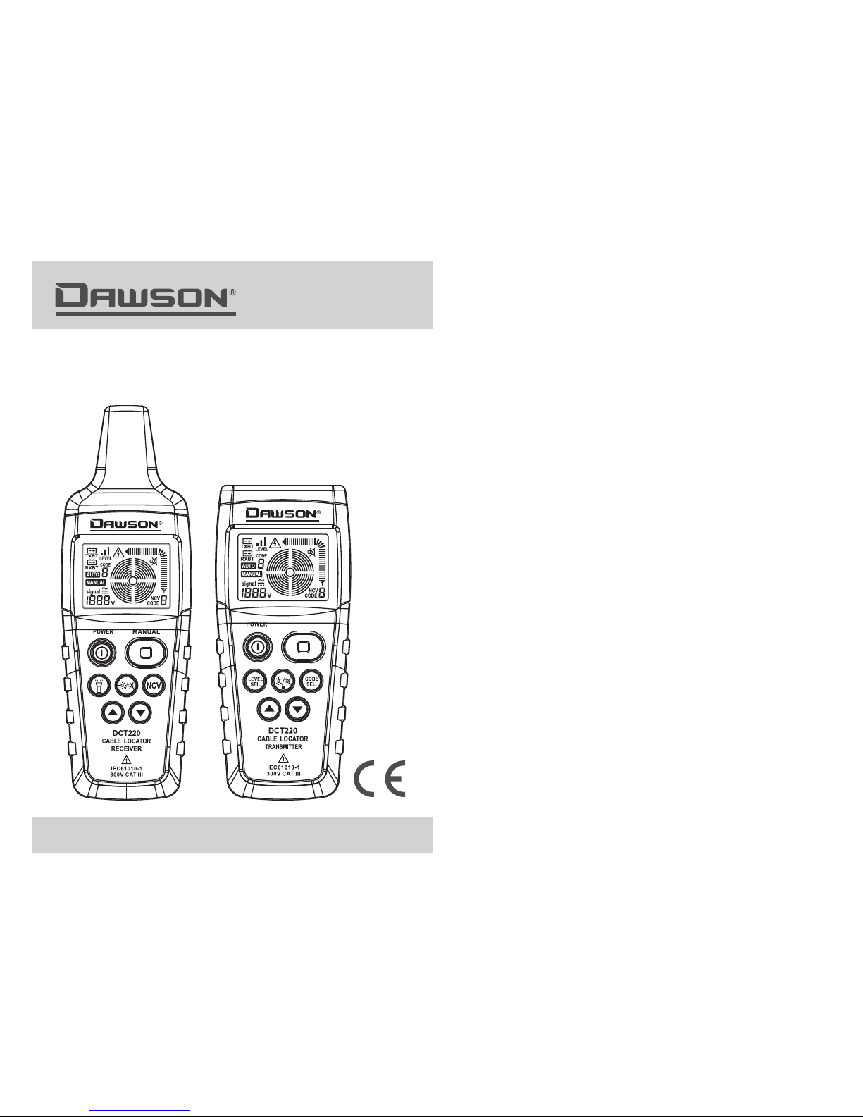
DCT220
CABLE LOCATOR
User’s Manual
CONTENTS CONTENTS
Safety Information ....................................2
1.1 Proud uct intro duction...........................7
Open-case lnspection ................................1
1.2 Featu res..........................................8
1.3 Descr iption.......................................9
2. .....................12Measurement Preparation
2.1 Measurement precautions.................12
2.2 Connection Methods .......................13
2.3 Usage Example..............................15
3. ....................................17Using the Meter
3.1 One-p ole appli cation ..........................17
3.2 applica tion Dual-pole ........................27
1.Overview................................................7
3.3 Incre asing the e ffect ive detecting
radius in c harged ci rcuits.....................32
3.4 Non-C ontact Vol tage detection...............34
4.Other Functions......................................35
4.1 Voltme ter funct ionality on the transmitt er......35
4.2 Wor k light fun ction ...............................35
4.3 Back li ght funct ion ...............................35
5. .......................................36Specifications
5.1 Transmit ter Speci fications.....................36
5.2 Recei ver Speci fications........................36
4.4 Detec ting deep ly laid circuits...................35
4.5 Auto po wer off f unction ..........................35
6. .........................37Repair and Maintenance
6.1 Troubles hooting .................................38
6.2 Check ing the tra nsmitter's fuse................38
6.3 Clean ing.........................................39
6.4 Repla cing the ba ttery...........................39
6.5 Calib ration.......................................40
Contact Dawson....... .................................40
01 02
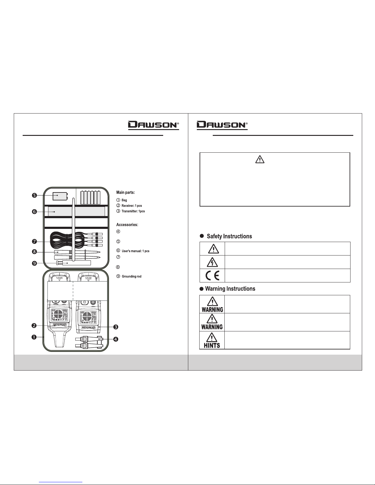
OPEN-CASE INSPECTION
When rece iving the C able Locator,please it
careful ly to ensur e no damage has occurred duri ng
transpo rt.Cont rol switches and connecto rs need to be
checked .If there i s any obviousdamage or func tional
failure ,please c ontact your supplier.
inspect
All igato r clips : 2 pcs
(1 re d and 1 bla ck)
Bat tery: 2 p cs
(9V a lkali ne batt eries )
Test l eads: 2 p cs
(1 re d and 1 bla ck)
Test p robes : 2 pcs
(1 re d and 1 bla ck)
SAFETY INFORMATION
WARNING
This cable locator is produced in accordance with
safety specifications for electronic testing instruments.
Before using this device, please read this manual
carefully and follow all procedures within. Failure to
do so could lead to personal injury or damage to the
meter.
Safety Symbols
Before us ing this pr oduct,please read the fol lowing
safety in structi ons carefully.
Importa nt inform ation. Read manual
before us ing.
Danger; u se cautio n.
Unit conf orms to Eur opean Union (EU)
safety st andards .
Misuse ma y cause per sonal injury or
damage to t he meter.
Misuse ma y cause per sonal injury or
damage to t he meter.
Suggest ions or tip s for operation.
03 04
Attenti on
Please ob serve the f ollowing instructions t o ensure sa fe
operati on and opti mal performace.
1)Preli minary In spection
Check the meter and accessories thoroughly before use.
Contact your local distributor if the meter or any components
are damaged or malfunction.
WARNING
Follow all standard safety procedures regarding the
use of electrical testing instruments when using the
cable locator.
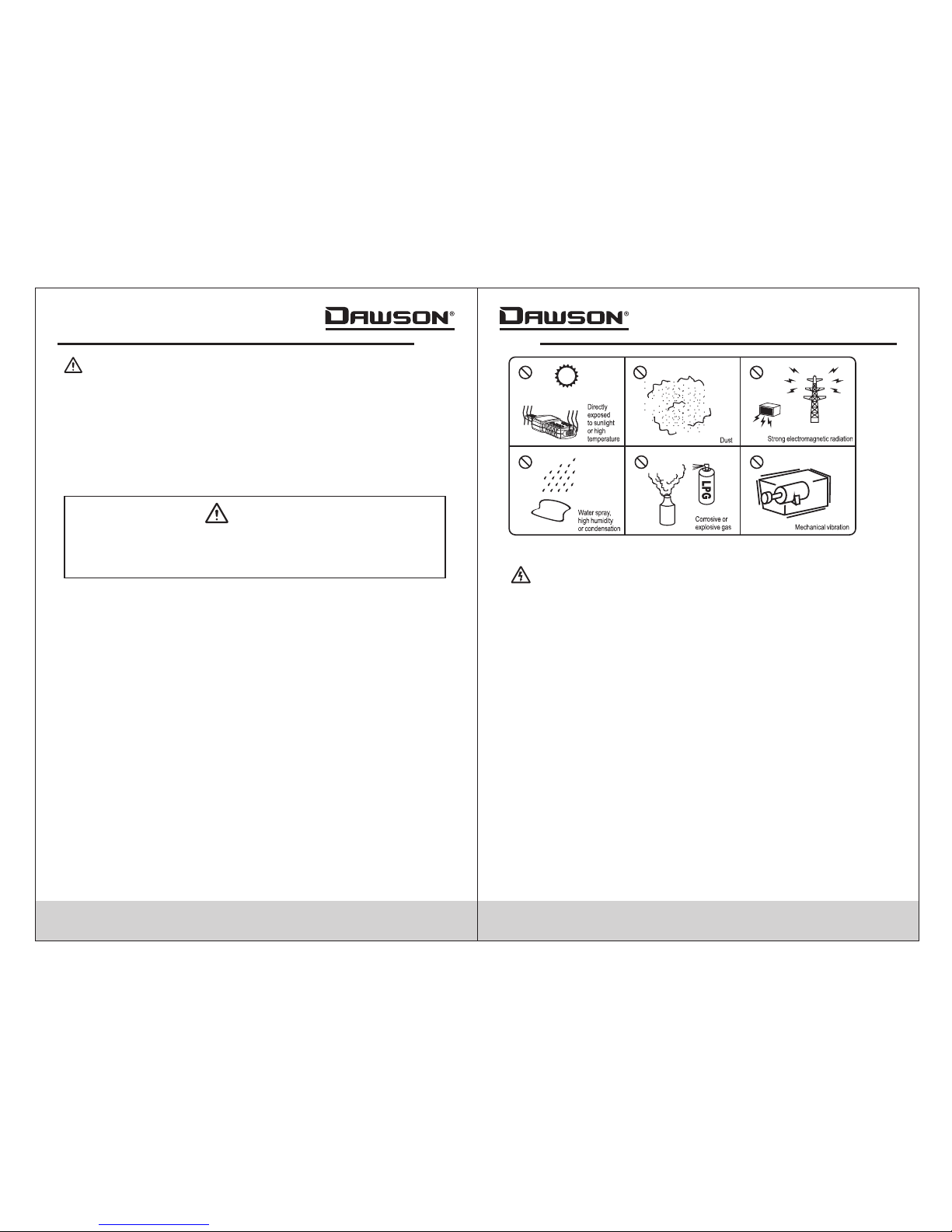
2)Place ment
To avoid fail ures,pl ease don’ t place the cable lo cator
under the f ollowin g environments:
• Avoid direct exposure to sunlight to ensure extended life of
the meter.
• Do not place the meter in any environment with high
pressure, high temperature, dust, explosive gas or vapor.
• Do not place the meter near a strong magnetic field which
may cause false readings.
• Avoid placing the meter on any surface with a high
mechanical vibration.
3)Use
To prevent personal injury or damage to the meter
during use, the following safety instructions should
be carefully observed.
1. Follow all industrial safety codes to avoid electric shock
when using the meter on live circuits.
2. Always use caution when working with voltages above
60VDC or 30VAC rms. Keep fingers behind probe barriers
at all times.
3. Observe the polarity of the battery when changing.
Reversing the battery polarity can damage the meter and
cause a potentially dangerous situation.
05 06
WARNING
1. Measurements near electrical installations should only be
performed by professionals.
2. Remove test leads from any live circuit before disconnecting
leads from transmitter.
3. Do not dismantle battery.The electrolyte contained in a
battery has a high risk of corrosion if exposed.If the
electrolyte contacts skin or clothes, quickly rinse affected
area with water.If electrolyte contacts eyes, rinse with cold
water and contact a physician immediately.
4. As the connection of the transmitter with the mains may
generate circuit current of milliampere level,in live condition
the Grounding hole of the transmitter can be only connected
with a neutral conductor. If transmitter connection is
reslized from the phase towards the protective conductor,the
functional safety of the protective conductor must be tested
first,in compliance with DIN VDE 0100.The reason is that
when connecting the transmitter from phase towards ground,
all parts being connected to the earth may be live in the
event of an error(if the earth resistance does not comply with
the prescriptions).
5. Do not use the instrument if the safety of the user cannot
be ensured.
Potential examples are:
• Signs of obvious damage to the unit.
• Measurement results highly deviate from estimated result.
• Instrument stored in unsuitable conditions for extended period.
• Instrument was subjected to physical/mechanical stress
during transport.
6. This instrument is designed to be used as specified within
this manual.The safe use of the instrument cannot be
guaranteed with any modifications to the instrument.
1. Operating temperature of the instrument is
0-40°C (32-104°F).
2. Always protect the device against exposure
to excessive mechanical vibration or
dropping during use.
3. Calibration and repair should only be carried
out by trained personnel.
4. Check the instrument before initial use to
ensure no damage occurred during delivery.
Do not use the instrument if any damage is
observed.
5. Do not attempt to measure voltages that may
exceed the rated voltage listed in the
technical specifications.
6. Avoid exposure to direct sunlight to ensure
the long life of the instrument.
7. Do not place the instrument in a high
electromagnetic field to avoid inaccurate
readings.
8. Only use batteries as listed in the
specifications.
9. Avoid exposing the battery to humidity.
Replace as as the low battery symbol appears.
07 08
1. If the instrument has been stored in unfavorable
conditions, place the instrument in a more favorable
climate before using.
2. When the transmitter is connected to the mains, if
the negative side of the transmitter is connected to
the protective ground phase, the current leakage
(if any) in the power supply line may combine with
the current of the transmitter, which may lead to
tripping the circuit breaker.
3. Keep the original packaging for future shipping
purposes (ex. calibration)
1. OVERVIEW
1.1 Product Introductio n
This cable locator is a transmitter and receiver with advanced
integrated circuitry for a highly stable and reliable performing
meter. The transmitter sends a modulated AC digital signal
along the cable or pipe and moving the receiver along the path
of the cable or pipe to track it inside the wall.The receiver will
change tone based on the intensity of the signal received.
The transmitter also has built in AC/DC voltmeter capabilities
to display the voltage of the line being tested along with a
warning when testing live conductors.The cable locator is
useful in maintenance and construction/installation of
telecommunication lines, power lines and building pipelines.
1.2 Features
• Detecting cables, electrical lines, water/gas supply lines
buried in the wall/ground.
• Detecting breaks or shorts in cables and electrical lines
buried in the wall/ground.
• Detecting fuses and current directions.
• Detecting interruptions and short-circuits in floor heating;
• Integrated AC/DC voltmeter function to measure 12-400V.
• The sensitivity of the receiver can be adjusted manually or
done automatically.
• The receiver automatically detects the selected transmitted
signal.
• The receiver has a built in flashlight for use in dark areas.
• Both the transmitter and receiver have backlights for use in
dark areas.

1
2
3
4
5
6
7
1
2
3
4
5
6
7
8
9
10
Low Batte ry
Signal Le vel
Auto Dete ction Sen sitivity
Manual De tection
Sensiti vity
Signal St rength
Signal St rength( bar graph)
Audio Mut e
Detecti on Sensit ivity
NCV Mode
Signal Co de
1.3.3 Rec eiver
09 10
Receive r Tip
LCD Scree n
Power But ton
Flashli ght Butto n
Backlig ht/Audi o Mute Button
Up Button
Flashli ght(und er tip)
Manual Se nsitivi ty Button
Non-Con tact Volta ge Button
Down Butt on
1.3.4 Rec eiver dis play
1
3
4
5
6
7
8
9
10
2
1.3 Description
1.3.1 Transmitter
Ground(-) Jack
Input/Output(+) Jack
LCD Screen
Power Button
Power Level Select Button
Backlight/Audio Mute Button
Up Button
Start/Stop Tranmission Button
Code Select Button
Down Button
1.3.2 Transmitter display
Low Battery
Signal Level
Signal Code
AC/DC Voltage
Voltage Measurement
Audio Mute
Transmission Indicator
2
1
3
4
5
6
7
8
10
9
 Loading...