

Page 1

REPORT NO : HCT-F04-0314 FCC ID :RZEDV-201DM DATE :MARCH 26, 2004
ATTACHMENT E.
- USER’S MANUAL
HYUNDAI CALIBRATION & CERTIFICATION TECHNOLOGIES CO., LTD.
SAN 136-1, AMI-RI , BUBAL-EUP, ICHEON-SI,KYOUNKI-DO, 467-701,KOREA
TEL : +82 31 639 8518 FAX : +82 31 639 8525
www.hctec.co.kr
Page 2

Access Gateway
DV-201DM for H.323 &SIP
Internet Telephony Gateway System
User Guide
Page 3

Access Gateway
DV-201DM for H.323 & SIP
Internet Telephony Gateway System
User Guide
Page 4
Page 5

DV-201DM
Ch.1
System Overview
1 - 1
Page 6

DV-201DM for H.323 & SIP
1 - 2
Page 7

Contents
1 System Overview..................................................................................................... 5
1.1. System Features......................................................................................... 5
1.2. QoS enhancement functions....................................................................... 5
1.3. Operation and maintenance ........................................................................ 6
1.4. Service Configuration .................................................................................. 6
2 System Specification ............................................................................................... 7
2.1. Basic Specifications....................................................................................7
2.2. Hardware Handling ..................................................................................... 7
2.3. Input Power Specifications.......................................................................... 8
2.4. Environmental Conditions...........................................................................8
3 System Functions....................................................................................................9
3.1. Call Processing Functions........................................................................... 9
3.2. Analog FXS Control Functions.................................................................... 9
3.3. Emergency Call Switchover Function ......................................................... 9
3.4. DTMF / Call Progress Tone Detection & Generation Function...................9
3.5. Voice Compression & Decompression Function......................................... 9
3.6. VoIP Function............................................................................................ 10
3.7. TCP/UDP/IP Protocol Processing Function..............................................10
3.8. Ethernet Control Function.........................................................................10
3.9. FAX Relay Function..................................................................................10
3.10. Console Command I/O Function...............................................................10
3.11. Telnet Remote Control Function................................................................ 10
3.12. Diagnostic Function................................................................................... 11
3.13. DHCP Function.......................................................................................... 11
3.14. WEB-based Management Function........................................................... 11
3.15. Operation Authentication Function............................................................11
3.16. Configuration function with connected telephone......................................11
3.17. Remote Upgrade Function ........................................................................ 11
3.18. Configuration Data Server Function..........................................................12
3.19. TFTP/ FTP Processing Function...............................................................12
1 - 3
Page 8

DV-201DM for H.323 & SIP
This page is empty.
1 - 4
Page 9

1 System Overview
DV-201DM is a residential Dial up VoIP gateway with one -port voice interface that can
be easily connected to conventional telephones and/or PBXs. Using proprietary QoS
management system, the DV-201DM has the capability of transmitting optimal voice
quality under high data traffic conditions.
1.1. System Features
Voice over IP solution
Compliant with ITU-T H.323 specification & SIP and IMTC’s VOIP recommendation
Comprehensive support for industry-standard H.323/SIP Clients (Microsoft
NetMeeting)
Analog FXS Interface
Supports PSTN back-up in case emergency
Supports Multiple standard voice CODEC algorithms, including G.729.A, G.723.1
Supports standard Internet protocols including TCP/IP, UDP, and RTP/RTCP
Supports static IP and dynamic IP
Supports real time Fax (Fax Relay)
G.168 compliant echo cancellation
Voice Activity Detection (VAD) and Comfortable Noise Generation (CNG)
Supports MMC (Man Machine Command) and Web based management
1.2. QoS enhancement functions
G.168 echo cancellation
Voice Activity Detection (VAD)
Comfort Noise Generation (CNG)
Dynamic jitter buffer control
1 - 5
Page 10
DV-201DM for H.323 & SIP
1.3. Operation and maintenance
Supports command-line interface through ASCII terminal
Supports command-line interface through telnet client
Supports system management interface through Web browser
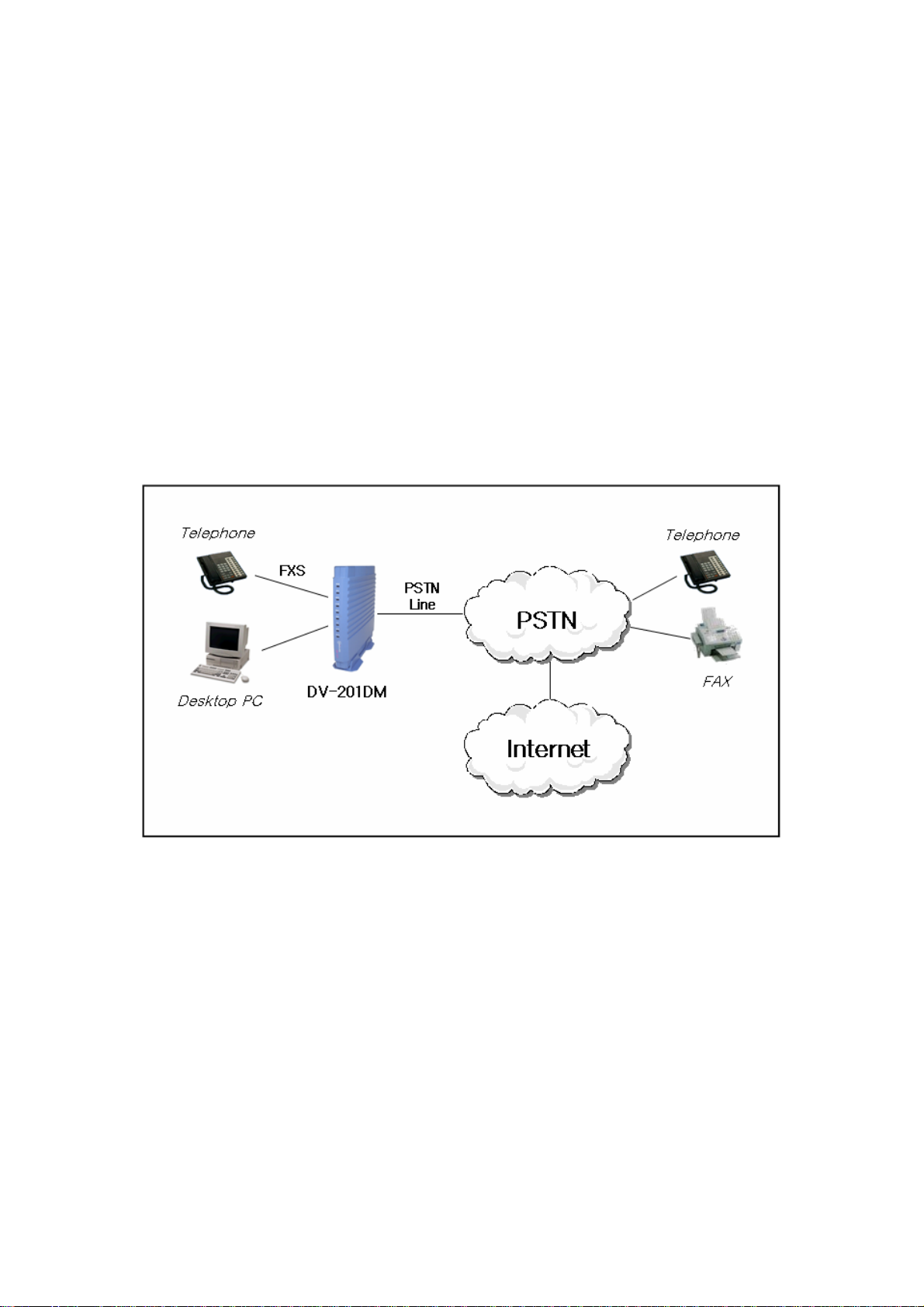
1.4. Service Configuration
Internet Telephony service network is configured as below.
1 - 6
Page 11

2 System Specification
2.1. Basic Specifications
Items Spec types
types DV-201DM
FXS
Interface
Signaling &
Protocol
Analog
WAN/LAN
Analog
Internet
Voice Capability
FAX Capability
Power
FXO
Back-Up
MODEM
10/100BaseT
PPP, DHCP, NAT
G.729A, G.723.1
Echo Cancellation(G.165), VAD/CNG
G3 FAX Relay(T.38)
External Adaptor
Input : 110~220VAC
Output : +5VDC
Note 1 : MODEM and Backup Line is the same interface
1
1
(note 1)
1
(node 1)
1
FXS/FXO
SIP, H.323,
2.2. Hardware Handling
The H/W is designed for easy maintenance and repair.
The H/W meets minimum requirements against electrical shock or accidental
impact.
1 - 7
Page 12

DV-201DM for H.323 & SIP
2.3. Input Power Specifications
Input Power Source : AC 110~240V (50/60Hz)
Voltage Fluctuating Range : ±10%
2.4. Environmental Conditions
Item Requirements
5 ~ 40℃
18 ~ 26℃
2 ~ 50℃
20 ~ 65%
45 ~ 55%
20 ~ 80%
Temperature
Humidity
Normal
Optimal
Minimal
Normal
Optimal
Minimal
Note) Minimal environment conditions may not exceed three consecutive
days or 15 total days per year.
1 - 8
Page 13

3 System Functions
3.1. Call Processing Functions
Call Processing Functions: Delivers voice via packetized network to call destination.
Basic Functions include:
- Inter-extension connection
- Monitoring/Error Management
3.2. Analog FXS Control Functions
Analog FXS Control Functions are used for SLT connection. It packetizes analog
voice and transmits through digital network to call destination. (call routing function).
3.3. Emergency Call Switchover Function
Emergency Call Switchover Function is a unique function compared to other devices.
The device automatically switches over to PSTN backup line when:
- Power failure
- Device Malfunction
3.4. DTMF / Call Progress Tone Detection & Generation Function
DTMF/Call Progress Tone Detection and Tone Generation Function detect and
generate inband-tone transmitted over an analog line.
3.5. Voice Compression & Decompression Function
Voice Compression is the packetizing of PCM-coded voice data. Decompression is
conversion of packetized voice data back into PCM-code. Supports G,729.a, and
G.723.1 Voice Coding mode.
The actual voice compression/decompression is processed inside of Digital Signal
Processor and the functional unit controls DSP H/W.
1 - 9
Page 14

DV-201DM for H.323 & SIP
3.6. VoIP Function
H.323 protocol provides voice service through IP network by way of sending digital
voice-data packetized and encoded via IP network to process its calls. This function is
complied with ITU-T : H.323 Recommendation.
SIP is a text-based protocol that is based on HTTP and MIME, which makes it suitable
and very flexible for integrated voice-data applications. SIP is designed for real-time
transmission, uses fewer resources and is considerably less complex than H.323. Its
addressing scheme uses URLs and is human readable.
3.7. TCP/UDP/IP Protocol Processing Function
TCP/UDP/IP Protocol Processing Function processes various Protocols like TCP
complying with RFC793, UDP with RFC768 and IP Protocol with RFC791.
3.8. Ethernet Control Function
Ethernet Control Function is to process MAC, Ethernet protocol or IEEE 802.3
Protocol and perform ARP for TCP/IP communications with CSMA/CD data network.
3.9. FAX Relay Function
FAX Relay Function is to send Facsimile Data instead of voice data through
packetized network so that FAX data may be packetized and terminated via internet.
3.10. Console Command I/O Function
Console Command I/O Function is to operate and manage the equipment through the
console at the site in which the equipment is installed. It decodes a command typed in
the console to perform the operation.
3.11. Telnet Remote Control Function
Telnet Remote Control Function is for an operator to access the equipment using
RFC854 Telnet Protocol in a remote system for operation and management. The
operator may see and maintain the system via access through Telnet from a remote
1 - 10
Page 15

location.
3.12. Diagnostic Function
Diagnostic Function is use when there is a need for customers or operators to test the
device. Test results give limited information to customer/operator but serves as a
vital tool to provide optimal customer service.
3.13. DHCP Function
DHCP Function is needed to dynamically assigned IP address, net-mask, and default
gateway for the DV-201DM. DV-201DM has DHCP client in it and performs the
function of changing IP addresses, net mask and default gateway.
3.14. WEB-based Management Function
Web-based management function is needed to set DV-201DM configuration
parameters remotely through web browser. Operator is permitted to access DV201DM to change configuration parameters through web browser or through HTTP
protocol.
3.15. Operation Authentication Function
Operation authentication function is needed to authenticate an operator by prompting
the user ID and password when the operator access DV-201DM
3.16. Configuration function with connected telephone
This function enable you to set DV-201DM initially using connected telephone. So you
don’t have to access to the device for setting with telnet or http connection. Just
connect telephone to the device.
3.17. Remote Upgrade Function
For remote maintenance or when S/W upgrade is necessary in the system using ftp
service.
1 - 11
Page 16

DV-201DM for H.323 & SIP
3.18. Configuration Data Server Function
With CDS Server, configuration data is downloaded to the system automatically and
automatically installed
3.19. TFTP/ FTP Processing Function
TFTP processing function is for remote maintenance and performs functions defined
in RFC1350.
FTP processing function is for remote maintenance and performs the functions
defined in RFC1986.
1 - 12
Page 17

DV-201DM
Ch.2
Installation and
Maintenance
2 - 1
Page 18

DV-201DM for H.323 & SIP
2 - 2
Page 19

Contents
1 Hardware installation & configuration ......................................................................5
1.1 Start Installation.................................................................................................5
1.2 Safety Warning ..................................................................................................5
1.3 How to install H/W..............................................................................................5
1.3.1 Cable Connection .................................................................................... 6
1.3.2 Connecting Ethernet cable.......................................................................6
1.3.3 FXS port...................................................................................................7
1.3.4 PSTN port................................................................................................ 8
1.3.5 Cable Length............................................................................................8
1.3.6 LED Status...............................................................................................8
2 How to install S/W..................................................................................................10
2.1 PC configuration ..............................................................................................10
2.1.1 Configuring Dynamic IP ....................................................................10
2.1.2 Force Static IP...................................................................................15
2.2 Accessing the system with HTTP .................................................................... 17
2.2.1 Logging in to the Web Manager.............................................................17
2.2.1 Using the DV-201DM Web browser.......................................................19
2.3 Accessing the system with TELNET .............................................................35
2.3.1 Basic Commands...................................................................................35
2.3.2 IP Configuration..................................................................................... 36
2.3.3 Modem Configuration..........................................................................38
2.3.4 Routing Table Configuration.................................................................. 42
2.3.5 Address Configuration Commands........................................................44
2.3.6 VoIP Configuration Commands (H.323) ................................................ 45
2.3.7 VoIP Configuration Commands (SIP)....................................................48
2.4 Configuring system with connected telephone ................................................50
2.4.1 Installation sequence............................................................................. 50
2.4.2 Voice Announcements...........................................................................51
2.4.3 Special dialing number for system management (Tone dialing
telephone only)
APPENDIX A How to use modem script.......................................................................53
...............................................................................................51
2 - 3
Page 20

DV-201DM for H.323 & SIP
This page is empty.
2 - 4
Page 21

1 Hardware installation & configuration
1.1 Start Installation
In this chapter, it will explain how to install DV-201DM. Connect power cable to DC
power input of system, and the other part of AC/DC adaptor to AC power source.
1.2 Safety Warning
When installing and operating the DV-201DM system, follow the safety guideline
provided below to help prevent serious injury and/or damage to DV-201DM system.
(1) Do not personally perform any maintenance (Unpacking) on this system. This
system does not contain any user serviceable parts. Maintenance is to be
performed only by qualified personnel.
(2) To avoid the risk electrical shock while installing H/W, you must remove the
power cord socket from the power connector on the back of DV-201DM.
(3) Put on a wristlet for preventing static electricity.
(4) Do not use any other power adaptor then the one provided with the DV-201DM.
(5) Maintain between 0℃ and 40℃ and it must be well ventilated
(6) When removing or connecting cables, always unplug DV-201DM power.
(7) Make sure all ventilation chambers are not obstructed at all times.
(8) Do not put heavy equipment and machinery on the system.
1.3 How to install H/W
(1) Place on a flat surface.
(2) Make sure that all rubber feet are attached. (for cooling system)
(3) Connect power cord to system.
2 - 5
Page 22
DV-201DM for H.323 & SIP
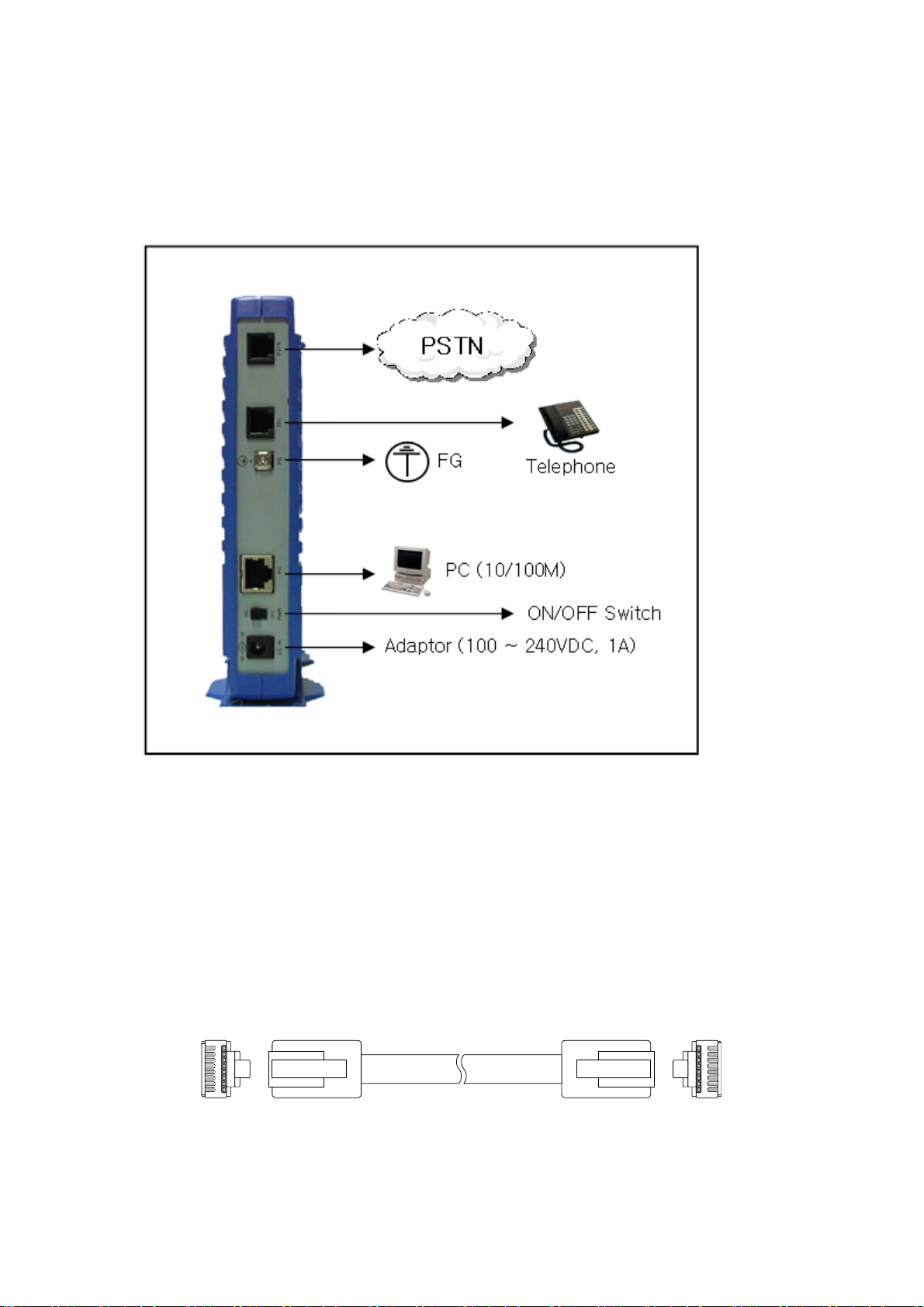
1.3.1 Cable Connection
Figure1 shows the cables are connected to rear of system.
<Figure 1> DV-201DM Cable connection
1.3.2 Connecting Ethernet cable
The Straight cable is also used to connect LAN port to a terminal like workstation,
PC, or notebook. When connecting LAN port to HUB, Cross-over cables must be
used.
Maximum length of RJ-45 should be less than 85m.
<Figure 2> RJ-45 cable (UTP cable)
2 - 6
Page 23

PC Port
12345678
1 : Rx +
2 : Rx 3 : Tx +
6 : Tx -
<Figure 3> Ethernet Port pin connection
RJ-45 Plug
( PC)
Pin Signal
connect
RJ-45 Plug
(PC Port)
Pin Signal
1 TX+ 1 TX+
2 TX- 2 TX3 RX+ 3 RX+
4 NC 4 NC
5 NC 5 NC
6 RX- 6 RX7 NC 7 NC
8 NC 8 NC
<Table 1> Connection between WAN port and modem
1.3.3 FXS port
FXS port is for telephone or FAX connection using RJ-11 connector to the terminal.
RJ-11 Plug
(Analog phone/Fax)
Pin Signal
Connect
Pin Signal
RJ-11 Plug
( FXS port )
1 NC 1 NC
2 NC 2 NC
3 Ring 3 Ring
4 Tip 4 Tip
5 NC 5 NC
6 NC 6 NC
<Table 2> FXS port cable pin connection
2 - 7
Page 24

DV-201DM for H.323 & SIP
1.3.4 PSTN port
This port is used for connecting to CO(Central Office) Trunk, connect to PSTN or
FXS I/F of PBX using RJ-11 Connector.
RJ-11 Plug
( PSTN )
Pin Signal
Connect
Pin Signal
RJ-11 Plug
( PSTN port )
1 NC 1 NC
2 NC 2 NC
3 Ring 3 Ring
4 Tip 4 Tip
5 NC 5 NC
6 NC 6 NC
<Table 3> PSTN port pin connection
1.3.5 Cable Length
Maximum Length of cable, which is connected to DV-201DM, must comply with
the following:
1 ) Ethernet
Maximum length of 10/100BaseT Ethernet is 330 feets/100 meters. (complies
with IEEE802.3 Recommendation)
2 ) Analog line
Maximum length of analog line is defined by loop resistance. Maximum loop
resistance is up to 600Ω (included telephone/voice switch).
1.3.6 LED Status
When DV-201DM comes up, you can judge the operation status of system by LED
status.
LED ON LED OFF BLINK
PWR
STS
LINE
PPP
Power ON Power OFF -
Device fault Device fault
Connected to modem Fail to connect Connecting
Connected to internet Connecting
Normal
operation
2 - 8
Page 25

G/K or CA
LAN
TEL
VOIP
PSTN
Registered Registering -
LAN cable is Connected LAN cable is Not connected -
OFF HOOK ON HOOK -
Calling via internet No call via internet -
Calling via PSTN No call via PSTN -
2 - 9
Page 26

DV-201DM for H.323 & SIP
2 How to install S/W
2.1 PC configuration
After installing system according to service network diagram of 1.2, access the
equipment using Telnet or Web browser, you should assigned IP address anywhere
between 192.168.1.1 and 192.168.1.253.
In next paragragh, we describe how to configure dynamic IP when DHCP server
function is activated. In 2.1.1 paragragh, we describe how to configure static IP
according to user’s network environment.
2.1.1 Configuring Dynamic IP
DV-201DM supports DHCP server function to assign private IP to PC. Our
software enables users to use DV-201DM in a Dynamic Network environment.
1. Open “Control Panel” and double click “Network and Dial-up connection” icon.
2 - 10
Page 27

2. Double click “Local area connection” in network connection window.
3. Click on “Properties” button.
2 - 11
Page 28

DV-201DM for H.323 & SIP
4. Select “Internet protocol (TCP/IP)” and click on “Properties” button.
2 - 12
Page 29

5. Select “IP address automatically and “DNS address automatically” in internet
protocol attribute window.
2 - 13
Page 30

DV-201DM for H.323 & SIP
6. Click “OK” button in internet protocol attribute window and then close all
windows opened.
7. Open “COMMAND PROMPT” window and Execute “ipconfig” command to
make sure that your PC is assigned IP address, subnet mask and default
gateway value.
(Verify: IP address range is between 192.168.1.10 ~ 192.168.1.29 )
Remember the IP Address value should be in 192.168.1.1~ 192.168.1.253,
subnet mask should be 255.255.255.0, and Default Gateway should be
192.168.1.254.
[c:\]ipconfig
Windows IP Configuration
Ethernet adapter local area connection:
Connection-specific DNS Suffix . :
IP Address. . . . . . . . . . . . : 192.168.1.10
Subnet Mask . . . . . . . . . . . : 255.255.255.0
Default Gateway . . . . . . . . . : 192.168.1.254
2 - 14
Page 31

2.1.2 Force Static IP
If your PC was not assigned IP information after the procedure above, you can
manually assign IP information by doing the following. From above, follow steps 1
through 4 then follow the procedures below.
1. Choose “Use the following IP address”, enter IP address, subnet mask, Default
gateway. If static IP is configured in DV-201DM, also enter DNS server
information.
IP address : any address of 192.168.1.1
through 192.168.1.253
Subnet mask : 255.255.255.0
Default gateway : 192.168.1.254
Note : When DV-201DM is allocated IP by DHCP protocol, input the value and
confirm DNS server address.
2. Click “OK” button, and close all windows.
2 - 15
Page 32

DV-201DM for H.323 & SIP
3. From windows, Goto “run”. Type in “command”. From “Command Prompt”
screen, type “ping 192.168.1.254” and press “Enter”. If the following
message is displayed, your computer is properly connected with DV-201DM.
[c:\]ping 192.168.1.254
Pinging 192.168.1.254 with 32 bytes of data:
Reply from 192.168.1.254: bytes=32 time=3ms TTL=255
Reply from 192.168.1.254: bytes=32 time=3ms TTL=255
Reply from 192.168.1.254: bytes=32 time=2ms TTL=255
Reply from 192.168.1.254: bytes=32 time=1ms TTL=255
Ping statistics for 192.168.1.254:
Packets: Sent = 4, Received = 4, Lost = 0 (0% loss),
Approximate round trip times in milli-seconds:
Minimum = 1ms, Maximum = 3ms, Average = 2ms
[c:\]
2 - 16
Page 33

2.2 Accessing the system with HTTP
2.2.1 Logging in to the Web Manager
Before accessing Web Manager, verify that the DV-201DM LEDs are blinking.
This indicates that the DV-201DM is ready to be configured.
1. Open a new Web browser window and enter the DV-201DM’s IP address,
192.168.1.254:8000 and press Enter.
2. Enter your user name and password.
The default user name is root and the default password is admin.
2 - 17
Page 34

DV-201DM for H.323 & SIP
3. When the DV-201DM Web Manager Opening page is displayed. You are
logged in.
2 - 18
Page 35

2.2.1 Using the DV-201DM Web browser
From main DV-201DM home page you can access any option by clicking the links
illustrated on the left column. For example: click the
Password link to access the System Information and Change Password page.
1. System Information and Change Password
System Information & Admin
The Change Password page shows the DV-201DMs name, current software
version and MAC address. You can also change the user’s password from this
page.
2 - 19
Page 36

DV-201DM for H.323 & SIP
2. PPP Configuration.
Click the
PPP Setting link to access the IP Configuration page, illustrated below.
This page displays the current PPP Configuration.
Any of parameters on the PPP Configuration page can be modified by simply
entering the desired values into the respective boxes.
Dialing Number : ISP’s Phone Number.
User Name : User ID given by ISP.
Password : Password of the user ID.
Connection Type : By default it is Always On.
Always On : In this mode the user is always connected to the ISP.
2 - 20
Page 37

Dial on demand : In this mode the user is connected to the ISP when he off
hooks the phone.
Idle timer : When the connection type is dial on demand and the user does not
use telephone or PC for idle timer value, the PPP connection is dropped
automatically.
Retry-Connection Timer : When the connection type is always on and the
connection to the ISP is disconnected, After Retry-connection timer value the
system will try to connect the ISP automatically. The Retry-connection timer value
should be at least 15 seconds. You can choose the number 15 to 30
Country Name : The name of your country, if your country name is not there you
can select similar country.
Dial Mode : The analog telephone line type.
Modem Speaker : To turn on and off Modem speaker.
2 - 21
Page 38

DV-201DM for H.323 & SIP
3. Speed Dial
Click the
below.
Speed Dial link to access the Speed Dial Configuration page, illustrated
Frequently dialed phone numbers can be stored for Speed Dialing.
2 - 22
Page 39

4.System Status
Click
System Status link to access the System Status page, illustrated below.
The system status page shows current Internet ,PPP and VOIP connection status.
This page is refreshed for every 20 seconds period.
Network port IP: Shows the WAN port IP address allocated by ISP.
PC Port IP: Shows the LAN port IP set by the user.
VOIP Status: Shows the registration state to proxy server or Gatekeeper.
PPP Status: Shows the Modem connection status and PPP status.
Modem Connection Speed: Shows the current modem connection speed.
2 - 23
Page 40

DV-201DM for H.323 & SIP
Modem Connection Time: Shows the modem connection time (PSTN call to ISP).
Last Error: Last Error code.
Modem Script Log: If Modem connection is failed, you can see the process of
dialing and connecting PPP.This page will be refreshed automatically for every
20 seconds period.
5. IP Configuration
Click the
IP Setting link to access the IP Configuration page, illustrated below.
Only root and manager can access this web page.
This page displays the current LAN IP Address and LAN mode.
Any of parameters on the IP Configuration page can be modified by simply
2 - 24
Page 41

entering the desired values into the respective boxes.
By default LAN mode is One IP.
In One IP mode, the NAT Is enabled and One IP is on.
In NAT Enable mode, the NAT is enabled and One IP is off.
In NAT Disable mode, the NAT IS disabled and One IP is off.
6. VoIP Setting
Click the
< H.323 setting >
VoIP Setting link to access the Port Configuration page, illustrated below.
2 - 25
Page 42

DV-201DM for H.323 & SIP
Only root and manager can access this web page.
You should enter Primary Gatekeeper IP Address, Secondary Gatekeeper IP
Address and H323 ID provided by Internet Telephony Service Provider.
Primary G/K IP address : It is the first G/K IP address
Secondary G/K IP address : It is the second G/K IP address. It is for redundancy
H.323 ID : G/W is authenticated from G/K with this ID.
Area Access Code : Area access code is automatically inserted before the dialed
digits when you place local calls.
Phone Number 1 : The telephone number assigned to FXS port 1.
Virtual Calling Number 1 : The CID assigned to FXS port 1.
Phone Number 2, Virtual Calling Number 2 : applicable to the DV-102 only.
PSTN Access Code : You can place the outgoing calls over the PSTN by dialing
PSTN access code first.
PSTN Ring Handling when Busy : The incoming PSTN call is ignored or
generates beep when the FXS port is used for a outgoing call.
Router Link Check : This option decide whether check link to default router or
not.
Using Digit Map : This option decide whether use digit map or not. It is only used
in Korea. To use other area and country, it have to be modified properly.
Phone Volume : Voice signal level from FXS to telephone can be changed. The
default value is 0, and can be set from –5 to +5.
Using VoIP Call Indication Tone: This option let customer distinguish VoIP call
from PSTN call. If you select “Yes”, when you call via internet, you will hear high
pitch sound when dialing
VoIP Call Listen Port : VoIP Call Listen port number can be changed. The default
value is 1720.
FAX : Whether FXS port is used for fax or not
2 - 26
Page 43

< SIP setting >
Click the VoIP Setting link to access the Port Configuration page, illustrated below.
Only root and manager can access this web page.
URL Mode: URL is Uniform Resource Locator, address-format to access specified
URL.
VoIP Server Name: Proxy Server name or IP address.
Service Domain Name: Domain Name.
VoIP User ID, VoIP User Password, VoIP Password Confirm:
DV-201DM is authenticated by proxy server with this ID and password.
Phone Number 1: The telephone number assigned to FXS port 1.
Area Code: You may insert a access code for security.
Ex. By inputting 15 into this box, you must dial 15 before dialing outbound on all
calls.
2 - 27
Page 44

DV-201DM for H.323 & SIP
PSTN Access Number: To use the emergency PSTN backup channel, you must
input an access code that opens the channel to access the PSTN line.
PSTN Automatic Rerouting: This option decides whether rerouting function is
used when Internet link is down or not.
PSTN Ring Handling when Busy: The incoming PSTN call is ignored or
generates beep when the FXS port is used for a outgoing call.
Using VoIP Call Indication Tone: This option let customer distinguish VoIP call
from PSTN call. If you select “Yes”, when you call via Internet, you will hear high
pitch sound when dialing.
Router Link Check: This option decide whether check link to default router.
Using Digit Map: Only used in Asia.
Caller ID Transmission: decides whether calling party number is sent or not.
Caller ID Receiving mode: When the G/W receive the originating number
information with a call, this option is used. You can configure with three types.
None, Korea, Japan.
2 - 28
Page 45

7. DHCP Server Configuration
Click the
page, illustrated below.
DHCP Server Setting link to access the DHCP Server Dial Configuration
Only root and manager can access this web page.
When using for DHCP Server setting, the starting IP address and the number of
DHCP clients needs to be configured
Allocated IP Addresses
When there are multiple users, this page shows the how IP addresses are
matched with each users’ MAC address.
2 - 29
Page 46

DV-201DM for H.323 & SIP
8. Forwarding Ports Configuration
Click
Port Forwarding link to access the Ports Configuration page, illustrated below.
Only root and manager can access this web page.
When the DV-201DM is used with the NAT server, all the packets from the specific
UDP/TCP ports are forwarded to the specified IP addresses.
2 - 30
Page 47

9. Restart System
Click
Restart link to access the Restart System page, illustrated below.
Only root and manager can access this web page.
To restart the system, click the Restart button.
You need to restart the system to apply the modified system parameters to the
system.
2 - 31
Page 48

DV-201DM for H.323 & SIP
10. Misc. Options setting
Click
Misc Options link to access the System Software Upgrade page, illustrated
below.
Only root and manager can access this web page.
The System software can be upgraded manually or automatically.
The server IP address is needed for the automatic upgrades.
The manual software upgrade procedure for DV-201DM is divided into stages.
Manual upgrade is only recommended for “Command Prompt” users.
1. Enable “S/W Manual Upgrading” option in “System Software Upgrade” page,
and press “Apply” button.
2. Download the files needed for upgrade from the Upgrade FTP server to a
client PC.
3. Open “Command Prompt” from Start Menu unde r Accessories or from “Run” and
type “cmd” followed by Enter.
4. Move to the directory containing the downloaded files.
5. Perform the upgrade batch command.
C:\upgrade\dv201dmsip.bat 192.168.1.254 " the batch file is dv201dmsip.bat
6. The “Command Prompt” window display the FTP procedure messages
2 - 32
Page 49

7. The system will be automatically restart, after completion of upgrade.
8. If log server feature is used, DV-201DM sends event messages to defined
server (using UDP port 514). Select “Used”, click “Apply” button.
When auto configuration feature is used, the created configuration data in CDS
server is downloaded to DV system. Select “Used”, enter the IP address of CDS
server and click “Apply” button. By using the CDS server, you can control the
configuration data of all systems remotely via the MAC addresses of each system.
11.Firmware Upgrade
Click
Firmware Upgrade link to access the Firmware Upgrade page, illustrated
below.
Only root and manager can access this web page.
We can upgrade firmware of our product from this web page.
Do not click other pages while your upgrading the firmware of the product, it will
result incompletion of upgradation.
2 - 33
Page 50

DV-201DM for H.323 & SIP
Click “Browse” button, choose binary file (ex, *.bin) for upgrading in your PC. And
Click “Open” button.
Click “OK” button, and DV201DM will be upgraded.
2 - 34
Page 51

2.3 Accessing the system with TELNET
For VoIP Services, there are many configuration values you need to set. You may
try telnet connection to set the configuration values. Detailed procedures are as
follows:
- Connect PC to PC port of DV-201DM
- Open a “COMMAND PROMPT” Command Window.
- Try pinging to 192.168.1.254. If you get response, you can proceed to the next
step.
- Type “telnet 192.168.1.254 6000”, and you can log-in to DV-201DM.
- Try “root” for login name, “admin” for password.
- Reply “DV_GW>”, you’ve accessed DV-201DM.
[Example]
Trying 192.168.1.254 (PORT: 6000)...
Connected to 192.168.1.254...
DV201DM Internet Phone Gateway System
Made by Davolink,Inc.
Motorola MPC850
SW: Release 1.00(2003-10-1 PM 06:23:26)
HW: MPU 0.51 (1Ch FXS + 1Ch FXO)
Now System Running...
Login: root
Password: *****
DV_GW>
2.3.1 Basic Commands
DIR (or LS)
“dir” is the same command as “ls” and displays the executable commands and
sub-directory which can be run in the current directory. The sub-directory is
displayed with “/” added after the last character to differentiate from the executable
commands. The following example is the result after executing “dir” command on
DV_GW> prompt, where DV_GW is system name. The capitalized letters in the
directory name and command name is the minimum number of characters to be
entered in changing a task directory or executing a command and they are used
as abbreviations for a directory or a command.
2 - 35
Page 52

DV-201DM for H.323 & SIP
[Example]
DV_GW> dir ©
SYstem/ COnfig/ Ftp_client/ Test/ Netutil/
STatistics/ Vocfile/ Debug/ Memory/
CD
"cd" is a command to change the working directory. A directory you want to move
can be given an direct path starting from a route directory or given a relative path
based on the current directory. It is possible to change directory by typing the
name of directory without “cd” command or by typing capitalized character of name
of destination directory. Same results are displayed in case of typing “cd system”
or in case of typing “system” or in case of typing “s” (minimized letter of destination
directory “system”). If only “cd” without any character is typed, they can see root
directory. The following example is an after executing “cd” command on root
directory.
[Example]
DV_GW> cd system ©
DV_GW/SYSTEM>
2.3.2 IP Configuration
1. Command directory
DV_GW/CONFIG/IP>
2. Command function
These commands are used for setting NAT Mode, IP address, subnet mask,
gateway, Ethernet address .
3. Available commands
Commands Description
SHOW Show IP parameters
CHANGE Change IP parameters
Ether set Set Ethernet address
2 - 36
Page 53

SHOW
This command display NAT Mode, IP address, subnet mask, and Ethernet
address, which are required to perform LAN service and WAN service.
Executing “show” at “DV_GW/CONFIG/IP)” prompt can see details.
[Example]
DV_GW/CONFIG/IP> show ©
-------- WAN Parameters -------------------------NAT mode - Enable
WAN IP Address - 0.0.0.0
WAN Subnet Mask - 0.0.0.0
WAN Gateway - 0.0.0.0
Ethernet Addr - 00:08:52:88:12:92
LAN IP Address - 192.168.2.12
LAN Subnet Mask - 255.255.255.240
LAN Gateway - 0.0.0.0
-------- DNS Parameters -------------------------DNS Not Used
--------------------------------------------------
CHANGE
This command used for setting NAT mode, IP address, subnet mask, and Ethernet
address.
Details can be seen by executing “show” at “DV_GW/CONFIG/IP>” prompt.
[Example]
DV_GW/CONFIG/IP> change ©
-------- WAN Parameters -------------------------NAT mode - Enable
WAN IP Address - 0.0.0.0
WAN Subnet Mask - 0.0.0.0
WAN Gateway - 0.0.0.0
Ethernet Addr - 00:08:52:88:12:92
LAN IP Address - 192.168.2.12
LAN Subnet Mask - 255.255.255.240
LAN Gateway - 0.0.0.0
-------- DNS Parameters -------------------------DNS Not Used
--------------------------------------------------
2 - 37
Page 54

DV-201DM for H.323 & SIP
1. Change NAT mode.
2. Change IP Address.
3. Change IP Netmask.
4. Change Def. G/W IP.
5. Change DNS Server IP.
6. Change DNS Domain Name.
0. Exit Menu.
What do you want to change (0-7) ? : 1
Enter mode (enable/disable) : enable
-------- WAN Parameters -------------------------NAT mode - Enable
WAN IP Address - 0.0.0.0
WAN Subnet Mask - 0.0.0.0
WAN Gateway - 0.0.0.0
Ethernet Addr - 00:08:52:88:12:92
LAN IP Address - 192.168.2.12
LAN Subnet Mask - 255.255.255.240
LAN Gateway - 0.0.0.0
-------- DNS Parameters -------------------------DNS Not Used
--------------------------------------------------
1. Change NAT mode.
2. Change IP Address.
3. Change IP Netmask.
4. Change Def. G/W IP.
5. Change DNS Server IP.
6. Change DNS Domain Name.
0. Exit Menu.
What do you want to change (0-7) ? : 0
You must RESET to apply modified value(s) to system.
©
©
©
2.3.3 Modem Configuration
1. Command directory
DV_GW/CONFIG/MODEM>
2. Command function
These commands are used for setting Modem configuration parameters.
2 - 38
Page 55

3. Available commands
Commands Description
SHOW Show Modem parameters
Dial number Command to set dialnumber
Username Command to set username
PAssword Command to set password
CONntype Command to set connection type
Idle timer Command to set the timer
COUntry Command to set country name
PUlsedial
SPeaker Command to set speaker
Retrytimer Command to set Retrytimer
SHOW
This command display Country name, User name, Dialing number, Connection
type, Modem speaker,Pulsedial,idle timer, default which are required to perform
Modem service.
Executing “show” at “DV_GW/CONFIG/MODEM” prompt can see details.
DV_GW/CONFIG>/Modem> show ©
-------------- MODEM/PPP Parameters ------------- Country (Company) - 61(KOREA)
Dialing Number - 533
User Name - davo
Password - drc
Connection Type - Allways Up(0)
Idle Timer - 0 sec
Re-connect Timer - 30 sec
------------------------------------------------- Pulse Dialing - OFF(Tone Dialing)
MODEM Speaker - ON
------------------------------------------------- Retry Timer - 30 sec
--------------------------------------------------
DV_GW/CONFIG/Modem> dialnumber 532 ©
..
Command to set Pulse dial
2 - 39
Page 56

DV-201DM for H.323 & SIP
...TConfig Writing Done
Dialing Number Changed to 532
DV_GW/CONFIG/MODEM> username guest ©
...
...TConfig Writing Done
User Name Changed to guest
DV_GW/CONFIG/MODEM> password guest ©
...
...TConfig Writing Done
Password Changed to guest
DV_GW/CONFIG/MODEM> speaker off ©
...
...TConfig Writing Done
MODEM Speaker Turned OFF
DV_GW/CONFIG/MODEM> conntype 1 ©
...
...TConfig Writing Done
Connection Type Changed to Dial Up(1)
DV_GW/CONFIG/MODEM> country ©
Usage : country <value>
<Value> - ITU-T T.35 AnnexA 8-bit country code (hexadecimal value)
00=JAPAN, 09=AUSTRALIA, 0F=BELGIUM, 16=BRAZIL
1B=BULGARIA, 26=CHINA, 31=DENMARK, 3C=FINLAND
3D=FRANCE, 42=GERMANY, 50=HONGKONG, 53=INDIA
57=IRELAND, 59=ITALY, 61=KOREA, 6C=MALAYSIA
73=MEXICO, 7B=NETHERLANDS, 82=NORWAY, 8A=POLAND
2 - 40
Page 57

8B=PORTUGAL, 9C=SINGAPORE, 9F=SOUTH AFRICA, A0=SPAIN
A5=SWEDEN, A6=SWITZERLAND, B4=UK, B5=USA
FE=TAIWAN
DV_GW/CONFIG/MODEM> country 53 ©
...
...TConfig Writing Done
Country Changed to 53(INDIA)
DV_GW/CONFIG/MODEM> pulse dial off ©
...
...TConfig Writing Done
Pulse Dialing Mode Changed to OFF (Tone Dialing)
DV_GW/CONFIG/MODEM> idle timer 0 ©
...
...TConfig Writing Done
Idle Timer Changed to 0(sec)
DV_GW/CONFIG/MODEM> retrytimer 15 ©
...
...TConfig Writing Done
Retry Timer Changed to 15(sec)
2 - 41
Page 58

DV-201DM for H.323 & SIP
2.3.4 Routing Table Configuration
1. Command directory
DV_GW/CONFIG/ROUTE>
2. Command function
Manages route table required for call routing.
3. Available commands
Commands Description
Show Command to show prefix table
Add Command to add numbers to route table required for call routing
Del Command to delete numbers registered in prefix table
SHOW
This command is used to display numbers registered in prefix table to the console.
When add command is successfully executed, the number is added in the blank
space in the following figure. Executing “show” at “DV_GW/CONFIG/ROUTE”
prompt shows current routing table.
[Example]
DV_GW/CONFIG/ROUTE> show ©
====================================================================
PREFIX TABLE
====================================================================
INTF PORT NUMBERS TRNC PREFIX POSTFIX EXTRA_INFO
====================================================================
FXS 0 200 0 0.0.0.0
FXS 1 201 0 0.0.0.0
IP 0 ~ 0 0.0.0.0
====================================================================
ADD
2 - 42
Page 59

This command used for adding numbers required for call routing to the routing
table. Executing “add” at “DV_GW/CONFIG/ROUTE)” prompt can see detailed
usage
[Example]
DV_GW/CONFIG/ROUTE> add ©
====================================================================
ADD Command Usage
====================================================================
add intf <port> nums <trnc> <pre> <post> <extra>
====================================================================
intf ; interface name (fxs, fxo, net)
port ; port number of interface (0 ~ )
nums ; prefix numbers ('0' ~ '9','.','*','#','~','?',',',NULL,
length: 20)
; '.' : virtual dial tone, ',' : pause(500ms)
trnc ; the number of truncation (0 ~ 31)
pre ; prefix number ('0' ~ '9',NULL)
post ; postfix number ('0' ~ '9',NULL)
extra ; extra-informations (hexa-decimal)
====================================================================
DV_GW/CONFIG/ROUTE> add fxs 0 3922241 0
Prefix Table Add success
DV_GW/CONFIG/ROUTE> add net 0 8~ 1 127.0.0.1
Prefix Table Add success
DEL
This command used for deleting number from the routing table. Executing “del” at
“DV_GW/CONFIG/ROUTE>” prompt can see detailed usage.
[Example]
DV_GW/CONFIG/ROUTE> del ©
====================================================================
DEL Command Usage
====================================================================
del all|[intf <port> nums]
====================================================================
intf ; interface name (fxs, fxo, net)
©
©
2 - 43
Page 60

DV-201DM for H.323 & SIP
port ; port number of interface (0 ~ )
nums ; prefix numbers ('0' ~ '9','*','#','~','?',NULL)
====================================================================
DV_GW/CONFIG/ROUTE> del fxs 0 200 ©
Prefix Table Delete success
2.3.5 Address Configuration Commands
1. Command directory
DV_GW/CONFIG/ADDRESS>
2. Command function
This command is used for managing a specified port number on FXS interface.
3. Available commands
Commands Description
Show show registered addresses
Myaddr register local addresses
SHOW
This command is used to display specified port number registered in address table.
Executing “show” at “DV_GW/CONFIG/ADDRESS>” prompt shows current
address table.
[Example]
DV_GW/CONFIG/ADDRESS> show ©
==========================================================
Address TABLE
==========================================================
INTF PORT LOCAL-ADDR PEER-ADDR GROUP-PORT
==========================================================
FXS 0 7183312
FXS 1 7183313
==========================================================
MYADDR
This command is used to register specified port numbers that are used as calling
party address in outgoing calls to track calls. Executing “myaddr” at
“DV_GW/CONFIG /ADDRESS>” to see usage details.
2 - 44
Page 61

[Example]
DV_GW/CONFIG/ADDRESS> myaddr ©
===============================================================
MYADDR Command Usage
===============================================================
myaddr intf <port> nums
===============================================================
intf ; local interface name(fxs,fxo)
port ; port number of interface (0 ~ )
nums ; destination address ('0' ~ '9','*','#',NULL)
===============================================================
DV_GW/CONFIG/ADDRESS> myaddr fxs 0 7183312
DV_GW/CONFIG/ADDRESS> myaddr fxs 0 null
DV_GW/CONFIG/ADDRESS> show
===============================================================
Address TABLE
===============================================================
INTF PORT LOCAL-ADDR PEER-ADDR GROUP-PORT
===============================================================
FXS 0
FXS 1 7183313
===============================================================
©
©
©
2.3.6 VoIP Configuration Commands (H.323)
1. Command directory
DV_GW/CONFIG/VOIP>
2. Command function
This command displays and sets up all the parameters required for the H.323.
Details can be seen by typing an appropriate command from the
“DV_GW/CONFIG/VOIP>” prompt to verify it.
Changes and verifies the parameters needed for H.323, the parameters are as
follows;
Parameter Description
G/K Interface Mode Connection mode of G/K.
E.164 Address IP address and Port number of the first G/K.
H.323 ID IP address and Port number of the second G/K.
RAS Parameters
Time out H.323 ID of the system
H.323 Prefix Prefix to be registered to G/K.
RAS TTL
Re-registration cycle (second) after first registration
to G/K.
2 - 45
Page 62

DV-201DM for H.323 & SIP
Protocol
Parameters
RTP Parameters
Manual RAS
Config
Q.931 Call Signaling
Channel Listen Port
Audio codec type Codec set used for a call set-up.
Fast Connect Used Use or not of the fast-connect protocol
H.245 DTMF Message
Fast Audio Connect
Force RBT to network
H.245 Tunneling Use or not of the H.245 tunneling.
BRQ Used Use or not of the BRQ message.
NAT Used Use or not of the NAT.
Discard non-fast alert
Using H.245 start
(outbound)
# Frame/Packet The numbers of frame per one IP packet.
Manual RAS Use or not of a Manual RAS.
Q.931 Call Signaling Port number when called.
Method of sending DTMF in a message format of
H.245
Use or not of the ring back tone from network in
ALERT condition.
The generation mode of a ringing tone to IP network
when the system has received an ALERT message.
Function of neglecting an ALERT message in a
condition that there is no audio information.
Use or not of the H.245 channel when starting a call.
3. Available commands
Commands Description
SHOW Shows VOIP parameter.
CONFIGURE Changes VOIP parameter.
SHOW
This command displays the set up value of the H.323 Parameter.
For detailed example, execute “show” from the “DV_GW/CONFIG/VOIP>” prompt
to verify it.
[Example]
DV_GW/CONFIG/VOIP> show ©
* RAS Parameters *
-----------------------------------------------------------------Gatekeeper not used.
* Registration Numbers *
------------------------------------------------------------------200 201 202 203
204 205 206 207
2 - 46
Page 63

-------------------------------------------------------------------
* My H323ID *
------------------------------------------------------------------DV116
-------------------------------------------------------------------
* Timeout *
------------------------------------------------------------------ RRQ timer mode : Received from G/K
RAS response timeout : 20 sec
RAS retry number : 2
Q.931 response timeout : 20 sec
-------------------------------------------------------------------
* RAS TTL *
------------------------------------------------------------------700
------------------------------------------------------------------Press any key to continue
* Protocol Parameters *
------------------------------------------------------------------Q.931 Call Signalling Channel Listen Port : 1720
Fast Connect Used : Yes
H.245 DTMF Message : Relay using using H245
UII.alphanume
ric
Fast Audio Connect : No
Force RBT to Network : No
Wait Alert Timer : 20000 msec
H.245 Tunneling : No
BRQ Used : No
NAT Used : No
Discard non-fast alert : No
Open H.245 when conneted(outbound side) : No
------------------------------------------------------------------Press any key to continue
* RTP Parameters *
------------------------------------------------------------------# Frame / Packet : 1
-------------------------------------------------------------------
CONFIGURE
Sets the parameters related to RAS, Protocol, RTP and Manual RAS requested in
H.323 protocol.
[Example]
DV_GW/CONFIG/VOIP> configure ©
1 . RAS Config
2 . Protocol Config
3 . RTP Config
2 - 47
Page 64

DV-201DM for H.323 & SIP
4 . Manual RAS Config
0 . Exit
Select (0 ~ 4):
2.3.7 VoIP Configuration Commands (SIP)
1. Command directory
DV_GW/CONFIG/SIP/CONF>
2. Command function
This command displays and sets up all the parameters required for the SIP.
Details can be seen by typing an appropriate command from the
“DV_GW/CONFIG/SIP/CONF>” prompt to verify it.
3. Available commands
Commands Description
SHOW Command to show all the parameters required for the SIP.
URLMODE Command to set URL mode(SIP or TEL) for peer UA.
MYDOMAIN Command to set service domain name.
MYTELNUM Command to set a telephone number assigned to FXS port 1.
PSVNAME Command to set proxy server name.
RGNAME Command to set registrar name.
AREACODE Command to set area code.
CONFAPPLY Command to restart SIP according to newly setting parameters.
SHOW
This command displays the set up value of the SIP Parameter.
For detailed example, execute “show” from the “DV_GW/CONFIG/SIP/CONF>”
prompt to verify it.
[Example]
DV_GW/CONFIG/SIP/CONF> show ©
SIP Configuration
URL mode sip
Register state C_Registered
Call state INITIAL
my domain davolink.co.kr
2 - 48
Page 65

my ipaddr xxx.xxx.xxx.xxx
my sip url sip:021234567@davolink.co.kr
my port 5060
my transport udp
Proxy server proxy-davolink.co.kr
Server name
Server port 5060
Server transport udp
Registrar name proxy-davolink.co.kr
Registrar port 8001
Registrar trans udp
Register timer 3600 sec
Payload type G723_63[004] G711U [000]
G723_53[102] G711A [008]
G729A [018] GSM [003]
Encoding name G723_63[G723-63] G711U[PCMA]
G729A[G729]
G723_53[G723-53] G711A[PCMU] GSM[]
Codec enabled G711U G711A G723_63
Areacode NONE
UserID
Password
2 - 49
Page 66

DV-201DM for H.323 & SIP
2.4 Configuring system with connected telephone
2.4.1 Installation sequence
1. Hardware Installation & Cable connection
z Place on flat surface and make sure that rubber feet are attached. (for cooling
system)
z Following figure shows the cable’s connections
2. System Configuration
CAUTION : In system configuration procedure at start, please eject a PSTN line
cable.
z System configurations of DV-201DM consist of following 2 parts.
- Internet setting : For PPP Connection, consist of the ISP phone number, user ID
and password.
- VOIP setting : For Internet telephony, you should set Proxy Server or Gatekeeper
and telephone number and so on.
z You can configure by using a telephone connected to TEL port and Web browser
of your PC. Configuration by telephone can be applied if you can not connect to DV201DM by web browser. We recommend using Web browser.
- Using telephone : please refer page 2-49,50.
z When you have configured system. Please inject a PSTN line. Make restart DV-
201DM by power switch and wait about 20~30 seconds until system is initialized.
3. Using VOIP service
z If you hear the dial tone at off-hook the telephone, you can use internet telephony.
Else Wait for connecting to internet.
z If you have problem with our system, please check system configurations or call
us +82-31-387-3240.
For a normal operation of DV-201DM, it takes about 30 seconds after power up. You
2 - 50
Page 67

may hear voice announcements such as “Network is not connected. Please …”. You
may check system status and a cause of connection fail by that.
2.4.2 Voice Announcements
You can hear following announcements when you can not use internet telephone
service. The following shows latest cause of connection fail. If you hear a same
announcement repeatedly, please check the cable connections or system
configurations.
“Network is not connected. Please wait while network is connected.”
Æ You might drop connection by “***#” or first time of trying to connect.
“Network is not connected. Because modem line was busy.”
Æ ISP phone number or your telephone line was busy.
“Network is not connected. Because modem has a problem.”
Æ Your PSTN cable has a problem. Or Modem detected “NO CARRIER”.
“Network is not connected. Because user authentication was failed.”
Æ User ID or Password for ISP are wrong. Or PPP has problems.
“Network is not connected. Because modem script was failed.”
Æ Remote PPP server doesn’t respond. Or script of system is not adapted ISP.
“Network is not connected. Because PPP negotiation was failed.”
Æ Remote PPP server has dropped the connection. Or some problems with PPP.
“Network is not connected. Because connection is dropped by idle timer expiry.”
Æ You have not used a telephone or PC for too long times.
Following announcements shows current internet connection status and VoIP status.
“We are connecting to network. Please wait while network is connected.”
Æ System is trying to connect. It takes about 30 seconds .
“Network is connected. But We are registering to proxy server. Please …”
Æ Now, system has been connected to internet. But it’s not registered SIP Proxy
server. Please wait until being registered to proxy server or Gatekeeper. It takes
some seconds.
2.4.3 Special dialing number for system management (Tone dialing
telephone only)
When you can hear a voice announcement or a dial tone at off-hook, You can check
or set the following configuration by dialing see the follows.
***0 DV-201DM will announce allocated IP address from ISP.
***1 DV-201DM will announce LAN (PC port) IP address set by user.
***2 You can change LAN (PC port) IP address.
2 - 51
Page 68

DV-201DM for H.323 & SIP
***3 You can change LAN subnet mask.
***4 You can change LAN Gateway address
***95 DV-201DM will announce current NAT mode
***961 Use OneIP mode (Allocated IP address of DV-201DM is same
as PC.)
***962 Use NAT mode (IP address of PC shall be private IP address)
***9876543210 restart DV-201DM immediately.
***9876546540 change all configurations to factory setting. And restart DV-
201DM immediately.
***# force to disconnect current PPP connection immediately.
2 - 52
Page 69

APPENDIX A How to use modem script
Caution : You don’ t have to modify modem script of DV-201DM in most of
environments. If your modem script is wrong, DV201DM don’ t operate right. So when
you modify modem script, be careful.
1. Overview
In DV-201DM, the script is provided for modem and PPP connection. In the script of
DV-201DM, loop and decision phase is not included, and user can configure the
minimal scenario for configuring modem & controlling PPP connection. In DV-201DM,
as the followings, two types of script are provided.
1) Setup script
Initialize & configure internal modem in DV-201DM.
2) Dial script
Configure the procedure of calling & PPP connection.
The follows is the initial value of script in DV-201DM.
Setup ₩N AT&F OK AT+GCI=61 OK ATTX4W1L3M1E0S95=47 OK AT₩₩N3B0 OK ₩N
Dial ₩N ATD₩T CONNECT ₩N
2. Operation of sript
The script of DV-201DM is divided according to space character and consisted of
receiving expectation character column and transmitting character column. The script
of above box can be divided into each character column and is as the follows. The
bold character is a receiving expectation character column.
1) Setup script
₩N - no receiving expectation character column
AT&F - initialize modem
OK - response of modem regarding to initializing modem
AT+GCI=61 - assignment country code
OK - completion of assignment country code
ATTX4W1L3M1E0S95=47 - configuration operation of modem
OK - completion of configuration operation of modem
AT₩₩N3B0 - configuration the second operation of modem
OK - completion of configuration the second operation of modem
₩N - no receiving expectation character column
2 - 53
Page 70

DV-201DM for H.323 & SIP
2) Dial script
₩N - no receiving expectation character column
ATD₩T - calling command
CONNECT - completion of connection
₩N - no receiving expectation character column
In DV-201DM, there are the reserved character columns for special function. The
reserved character columns are opened with “ ₩” character and the reserved length
is different according to the follow character. So be careful.
The reserved character columns are as follows.
character argument description example
s - Space character (SP) A₩sBC
t - Tab character (TAB) A₩tBC
n - Line feed (LF) A₩nBC
r - Carriage return (CR) A₩r₩BC
₩ - Back slash (₩) ₩₩N3
d ‘ 0’ ~’ 9’ Transmitting delay (Delay) A₩d2BC
c - Not included opening character +++₩c
T - Replacement character column with dialing
number (TEL)
U - Replacement character column with user ID
(USER)
P - Replacement character column with password
(PASSWORD)
N - NULL (no character column) ₩N
In DV-201DM, expansion character columns are supported. The expansion character
column is used for comparing “ receiving expectation character column” with “ predefined character column” and it is useful in environment with various expectation
character columns.
z &U
It is the expansion character regarding to user input prompt and DV-201DM compare
this character column with the following character column.
“ serid:", "ogin:", "userid", "user id", "login", "sername
z &P
It is the expansion character regarding to password input prompt and DV-201DM
ATD₩T
₩U
₩P
2 - 54
Page 71

compare this character column with the following character column.
“ assword:", "assword?”
z &C
It is the expansion character regarding to command input prompt and DV-201DM
compare this character column with the following character column.
"> ", "# "
"uthentication fail", "uthentication Fail", "nknown", "ogin incorrect"
3. Script command
In DV201DM, the following command is provided for modification/confirmation of
script.
command description
SHOW Display the current contents of script on screen.
SETUP Access the menu for modifying setup script.
DIAL Access the menu for modifying dial script.
EXP Add/remove a character column to/from expansion character
column.
EX. 1)
GW/CONFIG/MODEM> script ©
usage : script show|setup|dial|[exp add|del <name> <expand>]
show - show current MODEM scripts
setup - change script to initialize & setup MODEM
dial - change script to dial to PSTN(ISP)
exp - expand reserved script word (ex. &U usr)
EX. 2)
GW/CONFIG/MODEM> script show ©
========== MODEM SCRIPT ==========
setup : \N AT&F OK AT+GCI=61 OK ATPX4W1L3M1E0S95=47 OK AT\\N3B0 OK
\N
dial : \N ATD\T CONNECT \N &U \U &P \P &C PPP PPP \N
==================================
EX. 3)
GW/CONFIG/MODEM> script setup ©
[ \N AT&F OK AT+GCI=61 OK ATTX4W1L3M1E0S95=47 OK AT\\N3B0 OK \N ]
enter setup script : < new script >
2 - 55
Page 72

DV-201DM for H.323 & SIP
EX. 4)
GW/CONFIG/MODEM> script dial ©
[ \N ATD\T CONNECT \N &U \U &P \P &C PPP PPP \N ]
enter dial script : < new script >
EX. 5)
GW/CONFIG/MODEM> script exp add &C $ ©
Script Expand added &C, $
GW/CONFIG/MODEM> script show ©
========== MODEM SCRIPT ==========
setup : \N AT&F OK AT+GCI=61 OK ATPX4W1L3M1E0S95=47 OK AT\\N3B0 OK
\N
dial : \N ATD\T CONNECT \N &U \U &P \P &C PPP PPP \N
==================================
&C : $
==================================
EX. 6)
GW/CONFIG/MODEM> script exp del &C $ ©
Script Expand deleted &C
GW/CONFIG/MODEM> script show
©
========== MODEM SCRIPT ==========
setup : \N AT&F OK AT+GCI=61 OK ATPX4W1L3M1E0S95=47 OK
AT\\N3B0 OK \N
dial : \N ATD\T CONNECT \N &U \U &P \P &C PPP PPP \N
==================================
2 - 56
Page 73

12F, 1591-9, Anyang K-Center, Burim-Dong, Dongan-Gu
Anyang-City, Gyeonggi-Do, Korea
TEL : 82-31-387-3240 FAX : 82-31-387-3214
Homepage : http://www.davolink.co.kr
 Loading...