

Page 1

S
OLAR
R
ADIATION
S
HIELD
M
ANUAL
This instruction manual is designed to take you step-by-step through the process required to assemble and mount your Solar Radiation Shield. Please take
the time to read through this manual before beginning the process.
C
OMPONENTS
The Solar Radiation Shield includes the following components. Please make
sure you have all listed components before continuing.
✦
Radiation Shield Parts
a.
One Cover Plate
b.
One Support Plate
c.
One Flat Plate
d.
Three Closed Plates
e.
Three Open Plates
✦
Installation Hardware Kit
a.
Two Clip Mounts
b.
Three 1/2” (13 mm) Spacers
c.
Three 1” (25 mm) Spacers
d.
Three Plastic Screw Retainers
e.
One Cable Tie
f.
One Wall Mount Bracket
g.
Two 1 1/2” U-Bolts
h.
Four 1/4” Flat Washers
i.
Four 1/4” Hex Nuts
j.
One Cable Clamp
Page 2

Page 2 Solar Radiation Shield Manual
k.
Three #8 x 5” (127 mm long)
Threaded Rods with #8 Push Nuts
l.
Three #8 x 2 3/4” (70 mm long) Pan
Head Screws
m.
Three #8 x 1 3/4” (44 mm long) Pan
Head Screws
n.
Three #4 Flat Washers
o.
Four #4 x 1/2” (13 mm long) Pan
Head Self-Threading Screws
p.
Twelve #8 Flat Washers
q.
Nine #8 Split Lock Washers
r.
Six #8 Hex Nuts
s.
Three #8 Wing Nuts
T
OOLS
AND
M
ATERIALS
N
EEDED
In addition to the components listed above, you may need some of the following tools and materials. Read through this instruction manual before beginning
and be sure you have everything you need before beginning the installation.
✦
Small Phillips-Head Screwdriver and Medium Slotted-Head Screwdriver
✦
Wrench or Pliers
✦
Drill with 3/16” Drill Bit (4.7 mm)
To drill pilot holes if attaching Solar Radiation Shield to the top of a post.
✦
Adjustable Wrench or 11/32” Wrench and 7/16” Wrench
To tighten hex nuts (11/32” wrench) or to drive lag screws into wall or
post (7/16” wrench).
✦
Four 1/4” x 1 1/2” Lag Screws (38 mm long)
To attach Solar Radiation Shield to a post or wall.
✦
Three #8-32 x 1” Screws (25 mm long)
To attach Solar Radiation Shield over the top of a post (if #8 x 2 3/4” pan
head screws (provided) create clearance problems).
✦
Tape
To hold screws in place when assembling Solar Radiation Shield.
Page 3

Location Tips Page 3
L
OCATION
T
IPS
✦
The Solar Radiation Shield works best when in a location with a steady breeze.
Mount away from fences, buildings, trees, or other obstructions.
✦
Install over plants or soil if possible.
✦
Do not install over or near sprinklers. The Solar Radiation Shield is not designed
to protect the sensor from water sprayed upwards.
✦
If attaching to a building, the preferred location would be on the north side in the
Northern Hemisphere and on the south side in the Southern Hemisphere.
I
NSTALLATION
O
PTIONS
The Solar Radiation Shield may be mounted in three basic orientations: on the
side of a wooden post or a wall, on a metal pipe with outside diameter between
1” and 1 1/4” (25 mm and 31 mm), or on top of a wood post. Each of these configurations is pictured below. You should determine ahead of time which orientation best suits your purpose because the installation instructions differ
slightly depending on how you plan to finally mount the Solar Radiation
Shield.
I
NSTALLATION
O
PTIONS
Page 4

Page 4 Solar Radiation Shield Manual
A
TTACHING
THE
D
ATA
L
OGGER
The Solar Radiation Shield can house the HOBO Pro Series data loggers and
temperature sensors from the HOBO H8 Outdoor/Industrial 4-Channel External data logger. This includes the HOBO Pro H08-030-08 Temp, H08-031-08
T emp/External Temp, H08-032-08 RH/T emp and external temperatur e sensors
from the H08-008-04 HOBO H8 Outdoor/Industrial 4-Channel data logger.
Attaching the HOBO Pro Data Logger (all part numbers H08-030-08,
H08-031-08 and H08-032-08) to the Solar Radiation Shield
In order to attach the HOBO Pro data logger to the Solar Radiation Shield you
will need a closed plate, two #4 x 1/2” pan head self-threading screws, and the
HOBO Pro data logger. If you are installing a HOBO Pro P/N H08-031-08
Temp/External Temp logger you will also require a cable clamp, one #4 x 1/2”
pan head self-threading screw and a #4 flat washer.
1. Position the HOBO Pro data logger on the closed plate, lining up any two opposing
holes in the mounting posts, with the holes on the data logger mounting ears.
Make sure you orient the data logger with the metal base side against the
closed plate, and the label side away from the closed plate.
O
RIENTING
AND
A
TTACHING
HOBO P
RO
S
ERIES
LOGGERS
2. Using two #4x1/2” pan head self-threading screws, attach the data logger to the
closed plate.
Tighten to a snug fit only. Do not over tighten or you may crack the data logger mounting ears.
Note: If you have a HOBO Pro P/N H08-031-08, Temp/External Temp logger proceed with Step #3. If you
have HOBO Pro P/N H08-030-08, Temp or H08-032-08, RH/Temp loggers skip Step #3 and #4.
Page 5

Attaching the Data Logger Page 5
3. Place the cable clamp around the external temperature sensor cable on the HOBO Pro
Temp/External Temp data logger approximately 4” (10 cm) from the data logger.
S
ECURING
E
XTERNAL
T
EMPERAUTRE
C
ABLE
W
ITH
C
ABLE
C
LAMP
4. Attach the cable clamp to one of the remaining posts on the closed plate (using a
#4 x 1/2” pan head self-threading screw and a #4 flat washer) so that a loop
of cable is formed between the data logger and the cable clamp.
Make sure to mount the cable clamp with the flat side up and the bulge side
down. Tighten the screw snugly so that the cable cannot move easily
through the cable clamp if pulled on. When testing for a tight hold, do not
pull hard on the cable or you may damage it.
Attaching an External Temperature Sensor from the HOBO H8
Outdoor/Industrial 4-Channel External Logger to the Solar Radiation Shield
In order to attach an External Temperature Sensor to the Solar Radiation
Shield, you will need a closed plate, both clip mounts, the cable clamp, three
#4 x 1/2” pan head self-threading screws, three #4 flat washers, and the temperature sensor.
1. Place the sensor cable into the notch on one of the clip mounts and hold it in place.
Make sure to hold the clip mount so the raised semi-circle at the top of the
notch faces up.
2. Position the second clip mount over the first, with the notch facing in the opposite
direction, securing the sensor cable between the two notches.
When positioning the second clip mount, make sure the raised semi-circle
faces down.
S
ECURING
EXTERNAL
TEMPERATURE
C
ABLE
WITH
C
ABLE
C
LAMP
Page 6

Page 6 Solar Radiation Shield Manual
3. Position the clip mounts over two of the mounting posts on the closed plate.
Make sure you orient the clip mounts as shown in the figure below.
4. Attach the clip mounts to the mounting posts using two of the #4 x 1/2” pan head
self-threading screws and two of the #4 flat washers.
A
TTACHING
C
LIP
M
OUNTS
TO
S
OLAR
R
ADIATION
S
HIELD
5. Once secured, adjust the position of the sensor so the sensor and approximately 1/4”
(6 mm) of cable protrude from the clip mounts.
6. Place the cable clamp around the sensor cable approximately 8” (20 cm) from the
sensor.
7. Secure the cable clamp to one of the remaining mounting posts (using a #4 x 1/2” pan
head self-threading screw and a #4 flat washer) so that a loop of cable is formed.
Make sure to mount the clamp with the flat side up and the bulge side
down. Tighten the screw completely so that the cable cannot move within
the cable clamp.
S
ECURING
C
ABLE
W
ITH
C
ABLE
C
LAMP
Page 7

Assembling the Solar Radiation Shield to Attach to the Side of a Post, or to a Pipe. Page 7
A
SSEMBLING
THE
S
OLAR
R
ADIATION
S
HIELD
TO
A
TTACH
TO
THE SIDE OF A POST, OR TO A PIPE
.
The following instructions explain how to assemble the Solar Radiation Shield
for installation on the side of a post, or on a pipe. Please note, however, that if
you plan to mount the Solar Radiation Shield on top of a post, you should follow the instructions in “Assembling the Solar Radiation Shield to Attach to the
Top of a Post”
Assembling the Solar Radiation Shield Plates
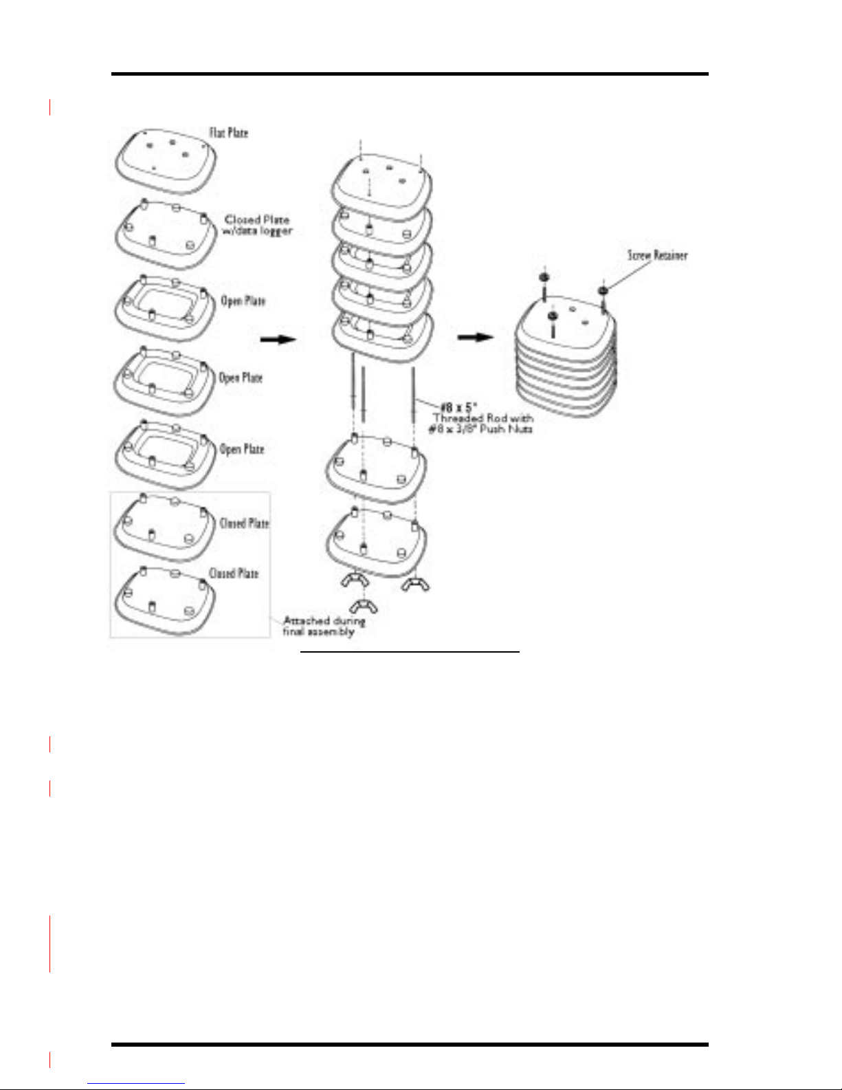
To assemble the Solar Radiation Shield plates you will need the flat plate, three
open plates, three closed plates (including the one to which you attached the
data logger), three #8 x 5” threaded rods with attached #8 push nuts, three #8
flat washers, three #8 split lock washers, and three plastic screw retainers.
1. Slide each of the three #8 x 5” threaded rods, with push nuts installed, through each
of the three holes in the three open plates
When inserting the threaded rods make sure that the long end (when measured from the push nut) goes through the holes in the open plates.
Note: If you have a HOBO Pro P/N H08-031-08, Temp/External Temp logger proceed with Step #2. If you
have HOBO Pro P/N H08-030-08, Temp or H08-032-08, RH/Temp loggers skip Step #2, and proceed with steps #3 and subsequent.
2. Feed the entire remaining length of external temperature sensor cable for the HOBO
Pro Temp/External Temp logger attached to the closed plate through the open centers
of the three open plates.
3. Slide the closed plate with the HOBO Pro logger over the threaded rod ends protrud-
ing from the top of the open plates so that the HOBO Pro logger is enclosed within the
center of the open plates.
If you are installing a HOBO Pro P/N H08-031-08 Temp/External Temp logger make sure that the external temperature sensor cable is pulled completely through the space within the center of the three open plates as the
Solar Radiation Shield is assembled.
4. Slide the flat plate over the threaded rod ends protruding from the closed plate with
the HOBO Pro logger.
5. Place plastic screw retainers over the protruding threaded rod ends.
6. Rest the partially assembled Solar Radiation Shield on a flat surface until the next step
(Attaching the Support Plate to the Cover Plate) is completed
Page 8
Page 8 Solar Radiation Shield Manual
.
ASSEMBLING THE RADIATION SHIELD PLATES
Attaching the Support Plate to the Cover Plate
To attach the support plate, you will need the cover plate, the support plate,
three #8 x 2 3/4” pan head screws, three 1” spacers, thr ee #8 flat washers, thr ee
#8 split lock washers, and three #8 hex nuts.
1. Slide the three #8 x 2 3/4” pan head screws up through the non-threaded holes in the
shield support plate.
Make sure the side of the support plate marked “UP” is in fact on top as you
slide the screws in from the bottom.
2. Place the cover plate over the screw ends protruding from the support plate.
3. Place a 1” spacer over each of the screw ends.
4. Secure the support plate and spacers to the cover plate using a #8 flat washer, #8
split lock washer, and #8 hex nut on each of the screw ends.
Tighten until the support plate is firmly attached to the cover plate.
Page 9

Assembling the Solar Radiation Shield to Attach to the Side of a Post, or to a Pipe. Page 9
ATTACHING SUPPORT PLATE TO COVER PLATE
Attaching the Cover Plate Assembly to the Solar Radiation Shield
1. Place the cover plate assembly onto the stack of plates, lining up the threaded rod
ends with the threaded holes in the bottom of the support plate.
2. Using your fingers, screw the three #8 x 5” threaded rods into the support plate until
tight.
ATTACHING THE COVER PLATE ASSEMBLY TO SOLAR RADIATION SHIELD
The Solar Radiation Shield has been designed for easy removal of the lower
two plates to allow quick access to the HOBO Pro data logger 3.5 mm jack cap.
The jack cap is removed from the HOBO Pro logger, enabling connection of the
computer interface cable, or HOBO Shuttle interface cable for data download.
For final assembly of the Solar Radiation Shield you will require the partially
assembled Solar Radiation Shield, with cover plate assembly attached, from the
prior step, two closed plates, and three #8 wing nuts.
If the final mounting method involves attachment to the top of a post, the
lower closed plate will have a Mounting Bracket attached to it.
Page 10
Page 10 Solar Radiation Shield Manual
1. Slide the lower closed plates over the threaded rods protruding from the bottom of
the partially assembled Solar Radiation Shield.
If you installed a HOBO Pro P/N H08-031-08 Temp/External Temp logger
in the partially assembled Solar Radiation Shield, make sure that the external temperature sensor cable is pulled completely through the space
between the lower open plate and the adjacent closed plate during this final
assembly
2. Screw the #8 wing nuts on the threaded rods protruding from the bottom of the
assembled Solar Radiation Shield until they are snug. Do not over tighten the wing
nuts, they should be easily removed for easy access to the HOBO Pro logger jack cap.
ASSEMBLING THE SOLAR RADIATION SHIELD TO ATTACH
TO THE TOP OF A POST
The instructions for assembling the Solar Radiation Shield differ slightly if you
plan to mount the Solar Radiation Shield on top of a wooden post. Follow the
instructions below if (and only if) you plan to ultimately mount the Solar Radiation Shield on top of a wooden post.
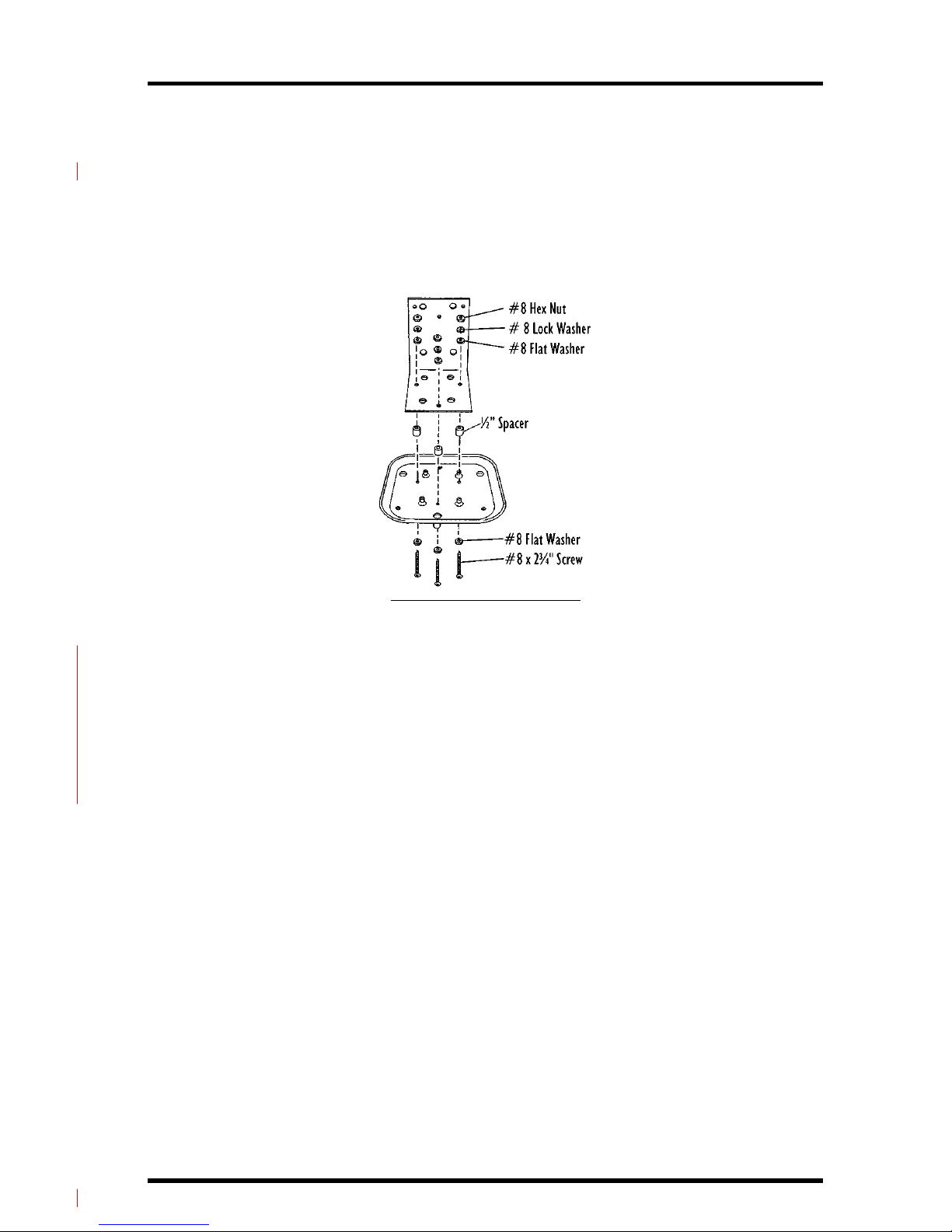
Attaching Mounting Bracket
To attach the mounting bracket you will need a closed plate, the mounting
bracket, three 1/2” spacers, three #8 x 2 3/4” pan head screws, six #8 flat washers, three #8 split lock washers, and three #8 hex nuts. You will also need a drill
with a 3/16” (4.7 mm) drill bit.
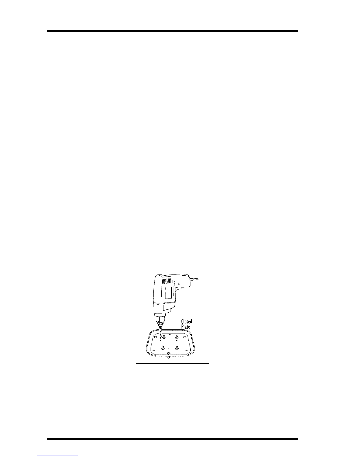
1. Using the power drill with 3/16” (4.7 mm) drill bit, drill three holes through one of the
closed plates in the locations marked by the small dimples on the bottom of the plate.
Do not use the closed plate to which you attached the sensor.
DRILLING HOLES IN CLOSED PLATE
2. Place a #8 flat washer over the end of each of the #8 x 2 3/4” pan head screws.
As long as the extra length of screw end protruding from the bottom of the
Solar Radiation Shield doesn’t create clearance problems when mounting
the Solar Radiation Shield, you can use the 8 x 2 3/4” pan head screws. If a
clearance problem exists, you will need to use #8 x 1” screws (not included).
3. Slide the three #8 x 2 3/4” pan head screws (with washers) up through the holes you
just drilled.
Page 11
Assembling the Solar Radiation Shield to Attach to the Top of a Post Page 11
4. At this point, you may want to place a small piece of tape over each of the screw heads
to keep the screws in place as you continue.
5. Place a 1/2” spacer over each of the screw ends protruding from the closed plate.
6. Slide the mounting bracket over the screw ends protruding from the closed plate.
7. Secure the mounting bracket to the closed plate using a #8 flat washer, a #8 split
lock washer, and a #8 hex nut on each of the screw ends.
Tighten until the mounting bracket is firmly attached to the closed plate.
ATTACHING MOUNTING BRACKET
Assembling the Solar Radiation Shield Plates
To assemble the Solar Radiation Shield plates you will need the flat plate, three
open plates, three closed plates (including the one to which you attached the
sensor and the one to which you attached the mounting bracket), three #8 x 5”
threaded rods with #8 push nuts, three #8 flat washers, three #8 split lock
washers, and three plastic screw retainers.
Page 12

Page 12 Solar Radiation Shield Manual
..
ASSEMBLING THE RADIATION SHIELD PLATES
Attaching the Support Plate to the Cover Plate
To attach the support plate, you will need the cover plate, the support plate,
three #8 x 1 3/4” pan head screws, three #8 flat washers, three #8 split lock
washers, and three #8 hex nuts.
1. Slide the three #8 x 1 3/4” pan head screws up through the non-threaded holes in the
support plate.
Make sure the side of the support plate marked “UP” is in fact on top as you
slide the screws in from the bottom.
2. Place the cover plate over the screw ends protruding from the support plate.
3. Secure the support plate to the cover plate using a #8 flat washer, #8 split lock
washer, and #8 hex nut on each of the screw ends.
Tighten until the support plate is firmly attached to the cover plate.
Page 13

Assembling the Solar Radiation Shield to Attach to the Top of a Post Page 13
ATTACHING SUPPORT PLATE TO COVER PLATE
Attaching Cover Plate to Solar Radiation Shield
1. Place the cover plate assembly onto the stack of plates, lining up the threaded rod
ends with the threaded holes in the bottom of the support plate.
2. With your finger screw the three #8 x 5” threaded rods with push nuts into the
shield support plate until tight.
ATTACHING COVER PLATE TO SOLAR RADIATION SHIELD
1. Slip the exposed ends of the #8 x 5” threaded rods through the holes in the open
plate and then the closed plate w/mounting brackets.
2. Screw the #8 wing nuts onto the exposed ends of the #8 x 5” threaded rods and
tighten until snug.
Page 14

Page 14 Solar Radiation Shield Manual
MOUNTING THE SOLAR RADIATION SHIELD
Follow the instructions below to mount the Solar Radiation Shield. There are
separate sections for each of the basic mounting options. You should modify
the instructions as necessary to fit your needs.
Mounting On the Side of a Post or Wall
In order to mount the Solar Radiation Shield onto the side of a post or wall, you
will need the Solar Radiation Shield assembly, three #8 split lock washers, three
#8 flat washers, and three #8 hex nuts. You will also need to supply four
1/4” x 1 1/2” lag screws.
1. Using four 1/4” x 1 1/2” lag screws (not included), attach the mounting bracket to the
mounting surface in the desired location.
ATTACHING MOUNTING BRACKET TO THE SIDE OF A POST
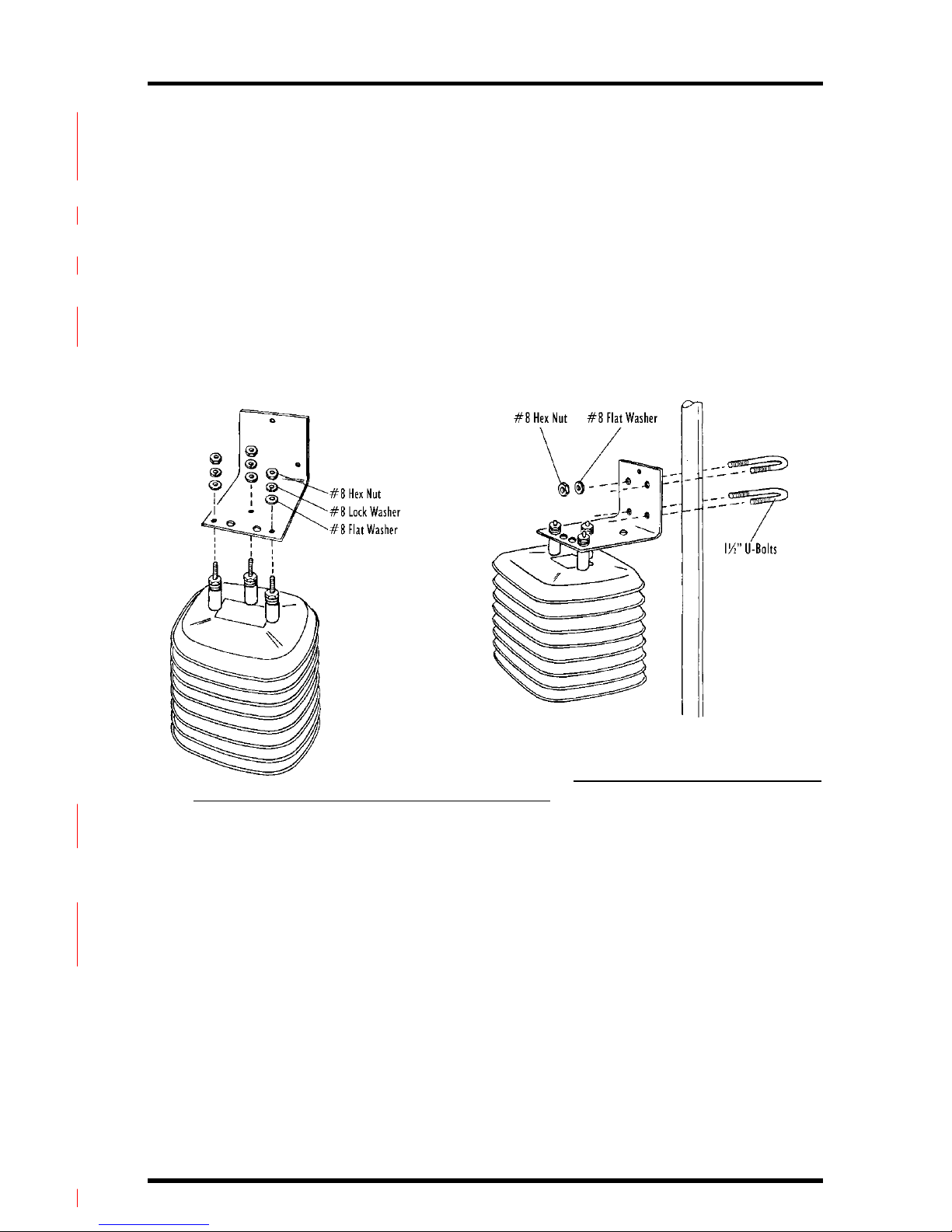
2. Slide the screw ends protruding from the top of the Solar Radiation Shield assembly
into the holes on the mounting bracket.
3. Secure the mounting bracket to the Solar Radiation Shield using a #8 flat washer , #8
split lock washer and #8 hex nut on each of the screw ends.
Tighten until the mounting bracket is firmly attached to the Solar Radiation
Shield.
ATTACHING SOLAR RADIATION SHIELD TO MOUNTING BRACKET
Page 15
Mounting the Solar Radiation Shield Page 15
Mounting on a Pipe
In order to mount the Solar Radiation Shield onto a metal pipe with outside
diameter between 1” and 1 1/4” (25 mm and 31 mm), you will need the Solar
Radiation Shield assembly, three #8 split lock washers, three #8 flat washers,
three #8 hex nuts, two 1 1/2” U-bolts, four 1/4” flat washers, and four 1/4”
hex nuts.
1. Slide the screw ends protruding from the top of the Solar Radiation Shield assembly
into the holes on the mounting bracket.
2. Secure the mounting bracket to the Solar Radiation Shield using a #8 flat washer, #8
split lock washer and #8 hex nut on each of the screw ends.
Tighten until the mounting bracket is firmly attached to the Radiation
Shield.
ATTACHING MOUNTING BRACKET TO A PIPE
ATTACHING SOLAR RADIATION SHIELD TO MOUNTING BRACKET
3. Hold the mounting bracket against the pipe and slide the ends of the two 1 1/2”
U-bolts through the holes in the back of the mounting bracket so that the U-bolts
wrap around the pipe.
4. Secure the mounting bracket to the pipe using a 1/4” flat washer and a 1/4” hex nut on
each end of the 1 1/2” U-bolts
Tighten until the mounting bracket is firmly attached to the pipe.
Page 16

Page 16 Solar Radiation Shield Manual
ATTACHING MOUNTING BRACKET TO THE TOP OF A POST
Mounting on Top of a Post
In order to mount the Solar Radiation Shield onto the top of a post, you will
need the Solar Radiation Shield assembly (with mounting bracket already
attached). You will need to supply four 1/4” x 1 1/2” lag screws.
To mount the Solar Radiation Shield, simply use the four 1/4” x 1 1/2” lag
screws (not included), to attach the mounting bracket to the mounting surface
in the desired location.
MAINTENANCE INSTRUCTIONS
✦ The effectiveness of the Solar Radiation Shield will be reduced if the surfaces of
the shield become dirty. Wipe the surfaces of the shield using a damp cloth to
remove dirt etc.
✦ Keep areas between Solar Radiation Shield plates free of debris that may obstruct
air flow e.g., leaves, twigs, webs, nests. DO NOT remove nesting insects or animals
by spraying insect killer of any kind into the Solar Radiation Shield because this
may damage the sensors and the Solar Radiation Shield.
© Davis Instruments Corp. 2000. All rights reserved.
 Loading...