

Davis Instruments Perception II, Vantage Pro, Weather Monitor II, Weather Wizard III, WeatherLink Getting Started Manual
...Page 1

WeatherLink
®
For Windows
®
For Vantage Pro®, Weather Monitor II®, Weather Wizard III® and
Perception II
®
Weather Stations
Product # 6510C & 7862
Getting Started
Guide
Page 2

FCC Part 15 Class B Registration Warning
This equipment has been tested and found to comply with the limits for a Class B digital device,
pursuant to Part 15 of the FCC Rules. These limits are designed to provide reasonable protection
against harmful interference in a residential installation. This equipment generates, uses and can
radiate radio frequency energy and, if not installed and used in accordance with the instructions,
may cause harmful interference to radio communications. However, there is no guarantee that
interference will not occur in a particular installation. If this equipment does cause harmful interference to radio or television reception, which can be determined by turning the equipment on
and off, the user is encouraged to try to correct the interference by one o r more of the follow ing
measures:
•Reorient or relocate the receiving antenna
•Increase the separation between the equipment and receiver
•Connect the equipment into an outlet on a circuit different from that to which the receiver
is connected
•Consult the dealer or an experienced radio/TV technician for help.
Changes or modifications not expressly approved in writing by Davis Instruments may void the
user’s authority to operate this equipment.
Product Number: 6510C, 7862
Davis Instruments Part Number: 7395.179
WeatherLink
®
for Windows Getting Started Guide
Rev. A (June 18, 2003)
© Davis Instruments Corp. 2003. All rights reserved.
Cover photo by Ronald Ross.
Vantage Pro, WeatherLink, Weather Monitor II, and Weather Wizard III are registered trademarks of Davis Instruments Corp. Hayes is a registered trademark of Hayes Microcomputer
Products, Inc. Windows is a trademark of Microsoft Corporation.
Page 3

WELCOME TO WEATHERLINK!
Welcome to WeatherLink!
Welcome to Davis Instruments’ W eatherLink for Windows. W eatherLink’s data
logger and so ftw a re connects a p ersonal compute r to your Davis weat her station,
allowing you to store, view, plot, analyze, export, and print your weather data.
The following Davis Instruments’ weather stations are supported: Vantage Pro
Vantage Pro Plus, Weather Monitor II
Contents of Package
Before continuing, please make sure your WeatherLink package contains the following listed items:
WeatherLink for Vantage Pro (#65 10C)
▲ Data Logger for Vantage Pro
▲ 8’ (2.4 m) cable with connector to link your station to your computer.
®
, Weather Wizard III®, and Perception II®.
®
,
▲ 9-pin (DB-9) PC COM Port Adapter (blue)
Use the 9-pin adapter to connect the data logger to a 9-pin serial port.
Note: If you need a 25-pin adapter, contact Davis Instruments Technical Support at 510-
732-7814.
▲ Loopback connector
The loopback connector is a short piece of cable with a phone plug at one end
and a red plastic cap at the other.
▲ WeatherLink Software CD ROM
WeatherLink for Monitor, Wizard and Perception (#7862)
▲ Data Logger for Monitor, Wizard and Perception
▲ 9-pin (DB-9) PC COM Port Adapter (black)
Use the 9-pin adapter to connect the data logger to a 9-pin serial port.
Note: If you need a 25-pin adapter, contact Davis Instruments Technical Support at 510-
732-7814.
▲ Loopback connector
The loopback connector is a short piece of cable with a phone plug at one end
and a red plastic cap at the other.
▲ WeatherLink Software CD ROM
1
Page 4

OPTIONAL ACCESSORIES
Hardware Requirements
Optional Accessories
The following optional accessories, desi gned for u se with WeatherLink, are available from your dealer or may be ordered directly from Davis.
▲ Telephone Modem Adapter
For transmission of data from the data logger using a modem.
▲ Standard 4-Conductor Extension Cable
For more flexibility in the placement of your console. Add one 40’ (12 m)
extension cable to extend the distance b etween your station an d the computer.
(48’ (14.4 m) maximum)
Hardware Installation
You can either install WeatherLink to use a direct, local connection between your
computer and weather station, or you can insta ll WeatherLink to use a modem
connection to a remote weather station. Requirements and installation for each
type of connection differ, and are explained separately below.
Hardware Requireme nts
The required hardware differs depending on whether you are making a local connection or a remote modem connection.
Local Connec tion Hardware Re quirements
The following ad ditional hardware is required for a lo c a l connection:
▲ Computer running Windows™ 95, 98, ME, NT 4.0, 2000, or XP with at least 5
MB of free disk space
The amount o f disk s pace nec essary de pends o n the ar chive interv al. Data base
files containing data stored at a 30 minute archi ve interval require approximately 132K of disk space per month of data. The file size changes in a linear
fashion depending o n the archive interval. For example, data stored at a 1–
minute interval requires approximately 3.9 MB per month while the data
stored at a 2–hour interval requires approximately 33 KB per month.
▲ Wi ndow s-Com pa tible Displa y
VGA minimum. SVGA or High (16-bit) Color recommended.
▲ One Free Serial Port
Remote Modem Connection Hardware Requirements
In addition to the provided hardware and the computer equipment listed above,
the following hardware is required f or a remote modem connec tion.
• One external modem to connect to the data logger at the remote site.
• One internal or external modem connected to your comput er
• Modems must be Hayes®–compatible and able to send data at 1200 , 2400,
4800, 9600, or 19200 baud for use with Vantage Pro stati ons or at 1200 or 2400
baud for use with a Monitor II, Wizard III, or Perception II weather station.
2
Page 5
LOCAL CONNECTI ON FOR VANTAGE PRO
Hardware Requirements
▲ Telephone Modem Adapter
The Telephone Modem Adapter is specially wired to provide the connection
between the data logger and the modem.
• Use a #6533 adapter with Vantage Pro Stations.
• Use a #7870 adapter with Wizard III, Mon itor II, and Percep tion stations.
A Few Notes About Remote Modem Connections
If you use a remote modem connection, WeatherLink will automatically dial the
station whenever you initi ate a program action that requires the software to talk
to the station .
Toolbar with On-Line Icon
While connected to a remote station, an “On-Line” icon appears in the toolbar.
This icon indicate s th at you a r e on-line and may be use d to h an g up a remote connection. To hang up, choose the On-Line icon from the toolbar or cho ose Hang Up
from the File menu.
By default, WeatherLink will hang up the connection to the modem after one
minute without any commu ni cat ion wit h th e stat ion . Use th e Serial Port dia log
box in the Setup menu of WeatherLink to change this default value. (See the
WeatherLink help files for more on this subject.)
Note: WeatherLink will not hang up the phone line if the bulletin, summary, or other windows
receiving real-time data from the console are active.
Local Connection for Vantage Pro
The instructions below explain how to make a typical local connection between
your Vanta ge Pro station and your computer.
Note: If you extend the cable run beyond 48’ (14.4 m), the software may have difficulty com-
municating with the station.
1. Enter the console’s Setup Mode by pressing and holding the DONE key,
then pressing the “DOWN arrow ” key.
Entering Setup Mode ensures that the station is not writing any data and
saves the current daily tota ls, highs, and lows to memory.
3
Page 6
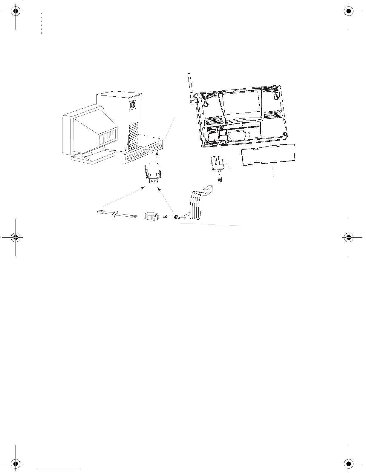
LOCAL CONNECTI ON FOR VANTAGE PRO
r
Hardware Requirements
2. Remove the battery cover from the console back and remove all power by
removing the batteries and AC-power adapter, if present.
Failure to remove power to the console before installing the data logger may
cause damage to the data logger or console.
Vantage Pro console
COM Ports
(DB-9)
9-pin connector
data logger
battery cove
8' (2.5 m)
data logger
cable
Optional 40' (12 m) 4-Conductor
Extension Cable and Coupler
Connecting your Computer Directly to your Weather Station
Connection
Options
3. Carefully insert the data logger into the large receptacle jack marked
EXPANSION inside the battery compartment
Guide the data logger cable through the square slot below the receptacle.
CAUTION: Make sure that whenever you connect or disconnect the logger from the
console that the console is NOT powered up. Plugging or unplugging the
data logger while power is applied can lock up or damage the logger.
4. Restore power to the weather station by reinstalling the batteries and reattaching the power adapter, if present.
The weather station should beep three times; each beep should occur within
about one second of the others.
5. Replace the battery cover, ensuring that the data logger cable exits through
the square slot.
6. Locate a free serial port on the back of your computer and connect the blue
DB9 to the port.
7. Insert the cable plug at the end of the short cable coming from the data logger into the receptacle on the end of the 8’ cable. Then insert the cable plug
on the end of the 8’ cable into the DB9 adapter.
The cable connecting the data logger to the computer is 8’ (2.4 m) long. If you
need to place the station cons ole more than 8’ from t he computer, use a 40’ (12
m) standard 4-conductor extension cable. Do not attempt to use more than 40’
of extension cable, or the data logger may have difficulty communicating with
the computer.
4
Page 7

REMOTE CO NNECTION FOR VANTAGE PRO
Hardware Requirements
Note: You do not need to keep the console connected to the computer for the logging to
work. You can connect the cable to the computer when you’re ready to download,
then disconnect it if you want to place the console somewhere else. However, you
can only run WeatherLink’s bulletin, summary, or other real-time windows if the console is attached to the computer.
8. Check the Baud rate settings on the console.
Enter the console SETUP mode by pressing and holding the DONE key, then
pressing the DOWN arrow key. Use the BAR and DONE keys to scroll to the
Baud Rate screen. The Baud Rate setting here on the console must be same as
that set in the WeatherLink software. Use the UP and DOWN arrow keys to
change the baud rate setting, if needed. Press and hold DONE to return the
console to current weather mode.
Remote Connection for Vantage Pro
Use a remote modem installation to connect your computer to a remote Vantage
Pro station. A remote modem installation involves connecting the data logger to
the weather station and to a mod em at the statio n console site and connecting
your computer’s modem to a phone line, which will allow you to dial the wea ther
station.
Note: Before installing the console and modem at a remote location, test the data logger
and connection first using a direct connection like that shown in the section above.
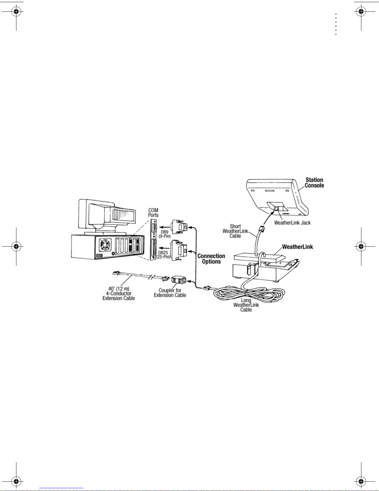
Remote Modem Installation Instructions
1. Install and set up an internal or external modem (according to the inst ruc t io ns
supplied by the manufacturer) for use with your computer.
Make a note of the COM port used by the modem . You will need this information when entering serial port settings for the station.
Vantage Pro console
data logger
battery cover
8' (2.5 m)
data logger
cable
5
Page 8

REMOTE CONNECTION FOR VANTAGE PRO
Hardware Requirements
2. At the station console site, put the external modem in a lo cation where it can
connect to both the logger and a phone jack and plug it into the phone jack.
IMPORTANT: DO NOT TURN THE MODEM ON AT THIS TIME.
The cable connecting the data logger to the modem is 8’ (2.4 m) long. If you
need to mount the station console more than 8’ from the modem, use a 40’ (12
m) standard 4-conductor extension cable. Do not attempt to use more than 40’
of extension cable, or the data logger may have difficulty communicating with
the modem.
3. Plug the external modem into the phone jack.
4. Place the console in setup mode.
Press and hold the DONE key, then press the DOWN arrow key. Entering
Setup Mode ensures the station is not writing any data to memory and saves
all current highs, lows, and daily totals.
5. Remove the battery cover from the console back and remove all power by
removing the batteries and AC-power adapter, if present.
Failure to remove power to the console before installing the data logger may
cause damage to the data logger or console.
6. Carefully insert the data logger into the large receptacle jack marked
EXPANSION inside the battery compartment
Guide the data logger cable through the square slot below the data logger
receptacle.
CAUTION: Make sure that whenever you connect or disconnect the data logger from
the console that the console is NOT powered up. Plugging or unplugging the
data logger while power is applied can damage or lock up the data logger.
7. Connect the blue Telephone Modem Adapter to the external modem.
Do not use a DB25 (not included) adapter and a gender changer to attach the
logger to a modem because it will not work. Do not use a black Davis telephone modem adapter, either, as it will not work with the Vantage Pro.
8. Insert the cable plug at the end of the cable into the Telephone Modem
Adapter.
9. Restore power to the weather station by reinstalling the batteries and reattaching the power adapter, if present.
The weather station should beep three times; each beep should occur within
about one second of the others.
10. Replace the battery cover, ensuring that the data logger cable exits through
the square slot.
11. Turn the modem ON.
Turning the modem on at this point allows it to receive the modem initialization string from the console.
12. Set the baud rate on the Vantage Pro console.
Enter Setup on the con sole by pr essi ng and ho lding the DON E key, then pressing the DOWN arrow key. Use the BAR and DONE keys to scroll through the
setup screens until you reach the BAUD RATE setup screen.
CAUTION:The Baud Rate setup screen will only appear if you have installed the data
logger.
6
Page 9
LOCAL CONNECT ION FOR MONITOR, WIZ ARD AND PERC EPTION
Hardware Requirements
▲ Use the up and down arrows to set the desired baud rate.
Use the fastest baud rate your modem can handle. 19200 is the fastest baud
rate available and is the default setting on the console.
▲ Press DONE when you’ve got the correct baud rate on the console screen.
Pressing DONE in this screen sends the initialization string to the modem,
so you don’t have to turn the console on and off agai n.
Local Connection for Monitor, Wizard
and Perception
The instruction s below explain how to connect your Weather Monitor II, Weather
Wi za rd III, or Perception II weather station directly to your computer.
Note: If you extend the cable run beyond 48’ (14.4 m), the software may have difficulty com-
municating with the station.
Typical Local Connect for Original Weather Stations
1. Make a note of the barometric pressure, total rainfall, and (if applicable)
calibration numbers.
You mus t remove power from the weather station console to install the data
logger. Removing power will cause these stored weather values to be erased.
Use WeatherLink to reenter these values after restoring power to the console.
2. Remove the mounting base from the console.
3. Remove all power from the cons ole by remo ving the power adapter a nd bat-
tery backup.
Failure to remove power before installing the data logger may cause damage
to the data log ge r and/or console .
4. A small switch near the data logger cables controls the baud rate. The
default setting is 2400 baud. If you need to run at 1200 baud, change the setting before connecting the data logger to the console.
7
Page 10

REMOTE CONNECTION FOR MONITOR, WIZARD AND PERCEPTION
Hardware Requirements
5. Connect the short data logger cable to the cable jack marked “WeatherLink”
on the bottom of your weather station console.
6. Restore power to the console by reattaching the power adapter and battery
backup.
The console should beep three times. The third beep, which should occur
within 30 seconds, indicates that the data logger is operating correctly.
7. Place the data logger inside the mounting base.
Placing Data Logger Inside Base
8. Reattach the mounting base to the weather station.
As you do so, guide all the cables through the slots on the mounting base.
9. Locate a free se rial port on the back of your co mpu ter and connec t the bla ck
DB9 adapter to the port.
10. Connect the long data logger cable to the DB9 adapter connector.
The cable connecting the data logger to the computer is 8’ (2.4 m) long. If you
need to place the station cons ole more than 8’ from t he computer, use a 40’ (12
m) standard 4-conductor extension cable. Do not attempt to use more than 40’
of extension cable, or the data logger may have difficulty communicating with
the computer.
Remote Connection for Monitor,
Wizard and Perception
You can connect your computer to a remote weather station using a modem. This
involves using the da ta log ger to c onn ec t the w ea th er st a tion console to a modem
at the remote site. Your computer can then use a modem to communicate to the
remote weather station via a phone line.
At Your Computer:
1. If you don’t hav e a modem, install and set up a n internal o r external modem
according to the instructions supplied by the manufacturer.
2. Connect the modem to the phone line.
8
Page 11

REMOTE CONNECT ION FOR MONITOR, WIZ ARD AND PERC EPTION
Hardware Requirements
At Your Weather Station Console:
3. Make a note of the barometric pressure, total rainfall, and (if applicable)
calibration numbers.
You mus t remove power from the weather station to install the WeatherLink
data logger, which will cause these values to be erased. Use WeatherLink to
reenter these values after re sto rin g power to the station .
4. Place the external modem in a location where it can connect to both the data
logger and the phone jack. Do not turn the modem on at this time.
5. Remove the mounting base from the weather station.
6. Remove all power from the weather station by removing the power adapter
and battery backup.
Failure to remove power before installing the data logger may cause damage
to the data logger and/or station.
Typical Remote Installation for Original Weather Stations
7. A small switch on the data logger near the cables controls the baud rate. The
default setting is 2400 baud. If you need to run at 1200 baud, change the setting before connecting the data logger to the console.
8. Connect the short data logger cable to the cable jack marked “WeatherLink”
on the bottom of your weather station console.
9. Connect the blue Telephone Modem Adapter to the external modem.
The Telephone Modem Adapter (#7870) i s r equir ed to us e the data logger with
a modem. A standard DB25 connector with a gender changer will not work.
The blue T elepho ne Modem Adapter (#6533) supplied for Vantage Pro stations
will not work either.
10. Connect the long data logger cable to the Telephone Modem Adapter.
11. Turn the modem on.
9
Page 12

SOFTWARE I NSTALLATION AND SETUP
Installing the Software
Note: It is very important to follow the order of these instructions. The modem must be con-
nected and turned on before you apply power to the weather station console.
12. Restore power to the weather station console by reattaching the power
adapter and battery backup.
The weather station should beep three times. The third beep, which should
occur within 30 seconds, indicates that the WeatherLink is operating correctly.
13. Place the data logger inside the mounting base.
14. Reattach the mounting base to the weather station.
As you do so, guide all the cables through the slots on the mounting base.
Placing Data Logger Inside Base
Software Installation and Setup
It is easy to install and setup WeatherLink on your computer.
Installing the Software
1. Place the Install Disk in your CD ROM drive.
2. The install program should start automatically. If the install program does
not start, choose Run from the Start menu, type D:\SETUP (or E:\SETUP,
substituting the correct drive letter for D or E), and choose OK to begin the
installation.
3. Follow the on-screen prompts to complete the installation.
Running the Software
To run the software, dou ble-clic k on t he WeatherLink ico n. If you hav e no st ation s
in the program directory when you run the software, the software will prompt
you to add a station (see below for details). If you have more than one station in
the program dir ectory w hen you run th e softwar e, the softw are will a utomatica lly
open the last station that was opened.
Note: To get the most use out of your WeatherLink software, please refer to the Weather-
Link Help.
10
Page 13

SOFTWARE I NSTALLATION AND SETUP
Stati on S etup
To interact with your station, you must add yo ur station to WeatherLink’s database, which means naming the station, configuring the software to work with that
station and w ith your compute r har dware , and set ting sta tion values such as time,
barometric pressure, total rainfall, and calibration numbers.
Adding a Station
1. Choose New Station from the File menu.
The software opens the Add New Station dialog box.
2. Type the station name into the text box.
The station name may be up to 40 characters/spaces long. Note that the software uses the first eight characters of the station name (not counting spaces or
punctuation marks) as the name of the directory into which it saves this station’s database and configuration files. The first eight characters of each station name must, therefore, be unique.
3. Choose OK.
The software saves the station, creates a directory and subdirectories for that
station, and prompts you to indicate whether you want to enter the walkthrough procedure.
Station Setup
About the Walkthrough
The software includes a station setup walkthrough that steps you through the station configuration procedure. After adding a new stati on, the software automatically asks you whether or not you want to be walk ed through the configuration
procedure. You can, of course, choose No and set up the st ation b y choos ing all of
the necessary commands from the menus. A Walkthrough command is included
in the Setup menu that lets you enter this procedure at any time.
Note: When necessary, the sof tware will automatically dial a phone modem station.
If you choose Yes to begin the walkthrough, the software takes yo u through the
the setup proces s, one dialog b ox at a time . The walkthr ough may va ry depending
on your station’s configuration.
At each step in the walkthrough procedure, the software will provide confirmation boxes prompting you to indicate whether or not you wish to continue. To
continue, choose OK. To skip any step and move to the next, choose Skip. To cancel the entire walkthrough procedure, choose Cancel.
Finding the Correct Serial Port
The software includes a procedure for locating the serial port to which your station is connected or determining whether that serial port is working. Using the
Loopback command (as opposed to Test) will help you find the correct port and
determine whether the serial port or the data logger is causing a communication
problem. The loopback function will also detect and report the presence of any
modems.
To use this procedure, you will need the loopback connector (the short cable with
a phone jack on one en d a nd a red plastic tip on th e other) supplied with Weatherlink.
11
Page 14

UPDATING P REVIOUS VERSIONS
Database Conversion
1. If necessary, disconnect the cable between yo ur station and th e adapter connected to the COM port.
2. Insert the loopback connector into the adapter.
3. In WeatherLink, click on Serial Port in the Setup menu.
The software opens the Serial Port dialog box.
4. Click Loopback.
The software will search all standard serial ports and inform you of the COM
port at which the loopback connector is located.
The software automatically selects the correct COM port for you in the Serial
Port dialog box. If it cannot find the loopback connector at any COM port,
your serial port may not be working. Consult your computer documentation
for help.
Loopback connector
Updating Previous Versions
WeatherLink versions 5.2 a nd late r use a dif fer ent re cor d struc tur e fo r storing data .
This change makes WeatherLink 5.2 and later versions incompatible with the data
files from earlier releases.
The following procedures explain how to convert older WeatherLink data files
(WeatherLink 3.x, 4.x, 5.0 and 5.1) for use wi th WeatherLink 5.2 and later. If you
are updating from version 5.0 or 5.1, there are also instructions on how to retrieve
additional existing data from your Vantage Pro data logger and incorporate it
with your weather data files.
Database Conversion
If you have an existing weather database from WeatherLink 5.1 or earlier (including versions of WeatherLink 3.x and 4.x), t her e ar e two w ays you can con vert those
files for use by WeatherLink 5.2+.
Convert a WeatherLink Station
This method conver ts all the da ta files in an exis ting WeatherLink sta tion dir ec tory
and retains the previously entered station configuration data.
1. Install the new version of WeatherLink in a new program folder.
1. Copy the station folder from your previous WeatherLink program folder to
your WeatherLink 5.2+ program folder.
2. Use the WeatherLink Open Station command in the File Menu to open the
copied station folder.
WeatherLink automatically detects that the station was created by a previous
version of the software and asks if you want to convert the data and station.
3. Choose OK to convert the station configuration, including the weather data
files.
WeatherLink automatically creates a backup copy of the old files and then
converts them for use by WeatherLink 5.2+.
12
Page 15

UPDATING P REVIOUS VERSIONS
Import Data Files
Import Data Files
This method allows yo u to selec t individu a l files or gr oups of files to be converted
for use by WeatherLink 5.2+.
1. Open WeatherLink 5.2+ and choose Impor t D atab as e Fil es from the File menu .
2. Select the data files you want to import.
You can select one file or multiple files in the same folder.
3. Choose OPEN to have the selected fil es c on verted. They will be put into a subdirectory called "Conv ert ed Datab a se Files" .
4. Copy the c onverted files to your station directory.
5. You will need to reopen your station i n WeatherLink be for e you w ill be able to
see the converted data files.
Retrieving 5.0 and 5.1 Data From the Data Logger
The archive memory in your Vantage Pro WeatherLink data logger contains data
not used by WeatherLink 5.0 or 5.1, such as UV, solar radiation, rain rate, and ET.
Depending on your archive interval, you may have up to 200 days of this data in
your logger.
To incorporate this data into your WeatherLink 5.2+ data files:
1. Choose New Station in the File menu to create a temporary weather station
folder.
2. Choose Download in the File menu or click on the download icon.
WeatherLink will do a full download of all data stored in the data logger.
3. Choose Browse in the Window menu or click on the Browse icon.
4. Scroll to the beginning of the data file, and write down the time and date of
the first entry in the database.
5. Open your original WeatherLink station using the Open Station command in
the File menu.
6. Choose Browse in the Window menu or click on the Browse icon.
7. Choose Delete Records in the Browse Menu
8. Select the reco rds for al l the day s following the ear liest date in your tempora ry
station database.
Note:Do not select the records for the day on which your temporary database begins. We
will individually delete the records for that day in the next step.
9. In the Browse Window, you will need to individually select and delete each
record in the data base that is dated after the earliest record in your temporary
database.
Note:WeatherLink only downloads data for dates and times not already in the database.
Deleting records allows it to download new data.
10. Choose Download in the File menu or click on the Download icon to download data from the data logger.
You should now have records in your data base up to the current time that
include all the new information that has been stored in your data logger.
11. Delete the temporary station you created in Step 1.
13
Page 16

TROUBLESHOOTI NG GUIDE
Recalculate THSW Index - Vantage Pro Only
Recalculate THSW Index - Vantage Pro Only
WeatherLink 5.3 and later supports a new derived data parameter, the Temperature Humidity S u n Wind (THSW) Index. If you have a solar radiation sensor, you
can have this value calculated for existing data by selecting the “Recalculate
THSW Index” command in the Browse Menu, which is displayed when the
Browse window is open.
Note: Be sure to verify that the latitude and longitude settings and daylight savings time set-
tings are correct before using this command.
Troubleshooting Guide
The following section answers som e of the most commonly ask ed question s about
®
WeatherLink
. Please consult this guide and WeatherLink Help b efore contacting
Technica l Support (see page 17).
Communications Prob lems
? Why can’t the WeatherLink software communicate with the data logger and sta-
tion?
If you are having trouble establishing communication between the weather
station and WeatherLink, s tart b y c hecking the weat her st at ion ’s own diagnostics. Remove all power to the weather station and then restart it by restoring
power (with the data logger still attached).
Note: Vantage Pro Only - The data logger uses non-vo l atile memory, so you won’t
lose any data you’ve already recorded. However, make sure to put the console in Setup Mode by pressing and holding the [DONE] key, then pressing
the [-] key befor e r emoving th e batteries. T his ensur es th e station will n ot try
to write any data as the power goes off.
• You should hear three beeps, each of which occurs when t h e weath er
station passes one of its diagnostic tests. Each beep follows the
previous after about one second. The first beep tells you the processor
is running. The second beep w ill be for the log ger (if inst all ed) an d the
third beep is for the display. If you do not hear one or more of these
beeps, contact Davis Instruments at 510-732-7814. (You’ll only hear two
beeps if you don’t have the data logger installed.)
• If you hear all three beeps, See “Finding the Correct Serial Port” on
page 11 for instructions on che c king your standard serial ports. If this
identifies a serial port other than the one you selected in station setup,
try connecting to the data logger again.
• Vantage Pro Only - make sure you are using the blue serial port
adapter sup plied with WeatherLink #6510C. The black Davis serial
adapters will not work.
• If you have a Monitor, Wizard or Perception station, make sure you are
using the black se ri al p ort adap t e r sup p lied with WeatherLink #7862.
The blue Davis serial adapters will not work.
14
Page 17

TROUBLESHOOT ING GUIDE
Program Problems
• Check the Baud Rate setting on t he console and in the s erial port dial og
box in the software. Make sure they’re set to th e same number.
Note: Enter the cons ol e’s Set up Mode by pressing and holdi ng the DON E key, then pre ss -
ing the DOWN arrow key on the console. Scroll through the setup choices by pressing the BAR or DONE keys until you reach the Baud Rate screen. This screen only
appears if the data logger is plugged into the console.
• Vantage Pro Only - Enter the console’s Setup Mode by pressing and
holding the [DONE] key, then pre ssing the [-] key on the console. Sc roll
through the setup choices by pressing the [BAR] or [DONE] keys unt il
you reach the Baud Rate screen. This screen only appears if the data
logger is plugged into the console.
• Monitor, Wizard and Per cept ion Only - Check the switch se tting on the
data logger. It will be set to either 1200 or 2400 Baud.
If you still cannot connect or if the loopback test identifies the serial
port you a lread y hav e sel ect ed, elim in ate th e fo llo win g pos sibi lit ies. If
you have questions on how to proceed, contact your PC vendor or PC
technical support.
▲ You have a hardware device conflict.
Check the dev ice mana ger tab in the Windows® syst em properti es dia log
box to ensure that Windows recognizes your COM port. Consult your pc’s
documentation to see how to access the system properties dialog box.
▲ Your serial port uses a non-standard device name.
WeatherLink recognizes serial ports named COM1 through COM10 only.
To use a modem, y ou must specify the underlying COM port on your PC.
To find out which port the modem’s connec ted to, you can loo k in Windows’ System Proper ties > Device M anager > “mod em name” Pr operties >
Modem > Port, where “modem name” is the name of the modem you have
installed.
▲ Your serial port is defective.
▲ The loopback connector or the WeatherLink adapter plug is bad.
Program Problems
? The barometer graph on the Bulletin does not “fill in” completely.
When you first load the bulletin, the barometer graph will only fill in completely when you have data in your database for the last six hours. Make sure
of the following:
▲ There is data in your database for the span of the barometer graph.
▲ The time and date of the stored barometer data is correct in your database.
▲ The time and date on the PC is correct.
▲ The time and date on the weather station are correct.
15
Page 18

TROUBLESHOOTI NG GUIDE
Program Problems
? No wind direction reading (or dashes instead of a reading) appears in my data-
base.
Be aware that if there is no wind speed when the direction is being sampled,
wind direc t ion is not recor ded. During inte rvals with no win d s p eed, no direction will be recorde d.
CAUTION:Since high wind speed is sampled more often, it is possible to have a high
wind speed but no wind speed.
? Vantage Pro Only: WeatherLink says “No new data to download” but I know
there’s data there. What can I do?
Vantage is smart enough to send only data it hasn’t already sent to the computer. So, when you initiate a new download, the program will retrieve the
fir st record aft er the last record shown in the WeatherLink’s Browse Window.
Older data is stored in the logger as a backup. To see how many of these
backup records are stor ed in the logger, create a new station and down load the
data into this new database. Because there are no records stored in the station
you just created, WeatherLink will download everything it has stored.
Next, try clearing the archi ve memory usin g the clear dialog box. You will lose
any data not already downloaded in your archive memory, but all of your c alibration numbers and alarm settings will remain intact. If this doesn’t work,
reboot your weather station (that is, remove, then restore all power to the station).
CAUTION:Make sure to put the console in Setup Mode (by pressing the DONE and
DOWN arrow keys) before removing the batteries. The ensures the station
will not try to write any data when the power goes off.
? Monitor, Wizard and Perception Only: My archive memory is empty and I know
it should not be. What can I do?
First try using the “Set Archive Interval” command in the Setup menu to clear
the archive memory and see if this corrects the problem. You will lose any
undownloaded data in your archive memory , but all your calibration numbers
and alarm settings will remain intact. If this doesn’t work, restart your
weather station by removing the AC power adapter and the backup battery
and then recon nec t ing th em . Al l da ta whi ch ha s not bee n dow nloa ded will be
lost. You will also have to reset all console settings such as the barometer, calibration numbers, and a larm settings.
? Monitor, Wizard and Perception Only: After successfully downloading, the data
does not appear in my database. Where is it?
The most likely possibility in this case is that the time and date on your
weather station are incorrect. This usually happens if there is a power outage
and you don’t res et the time and date afterwards. In this case the data was
written into the wrong time and month. Correctly set the time and date on
your weather station and all future data should download correctly.
It is also possible, if you have multiple stations, that you downloaded data
into the wrong station’s databa se. Make sur e the desir ed station is open before
downloading.
16
Page 19

TROUBLESHOOT ING GUIDE
Contacting Davis Technical Support
? When viewing data, dashes appear in place of a value for functions other than
wind direction. Why?
If no data was r ecor ded by a s ensor (for example, t he sens or was dis connected
or radio interference blocked reception) or if bad data was recorded for a sensor (for example, the sensor was malfunctioning), the software dashes out the
entry rather than showing invalid data. You can use the record editor to correct these entries.
? The data I want to see, such as humidity (Monitor), or solar radiation, soil mois-
ture, or Temp 2 (Vantage Pro) is miss ing complete ly or is gr e yed-out?
All optional sensor s must be enabled in the Station Configuratio n setup di alog
box before the data will be displayed in WeatherLink. If you are not seeing
data from a sensor that is installed in your weather station, be sure check the
Station Configuration in the Setup Menu and make sure the sensor has been
selected.
Contacting Davis Technical Support
If you have questions about WeatherLink software, or encounter problems
installing or operat ing the so ftwar e, ple ase con tact Davis Technical Support. Most
questions can be answered while you are on the phone.
Note: Sorry , we are unable to accept collect calls.
(510) 732-7814 – Monday – Frid ay, 7:00 a.m. – 5:30 p.m. Pacific Time
(510) 670-05 89 – Fax Technical Support
support@davisnet.com – E-mail to Technical Support
info@davisnet.com – E-mail to Davis Instruments.
www.davisnet.com – Copies of User Manu als are available on the “Support”
page. Watch for FAQs and other updates. Subscribe to the e-newsletter.
17
Page 20

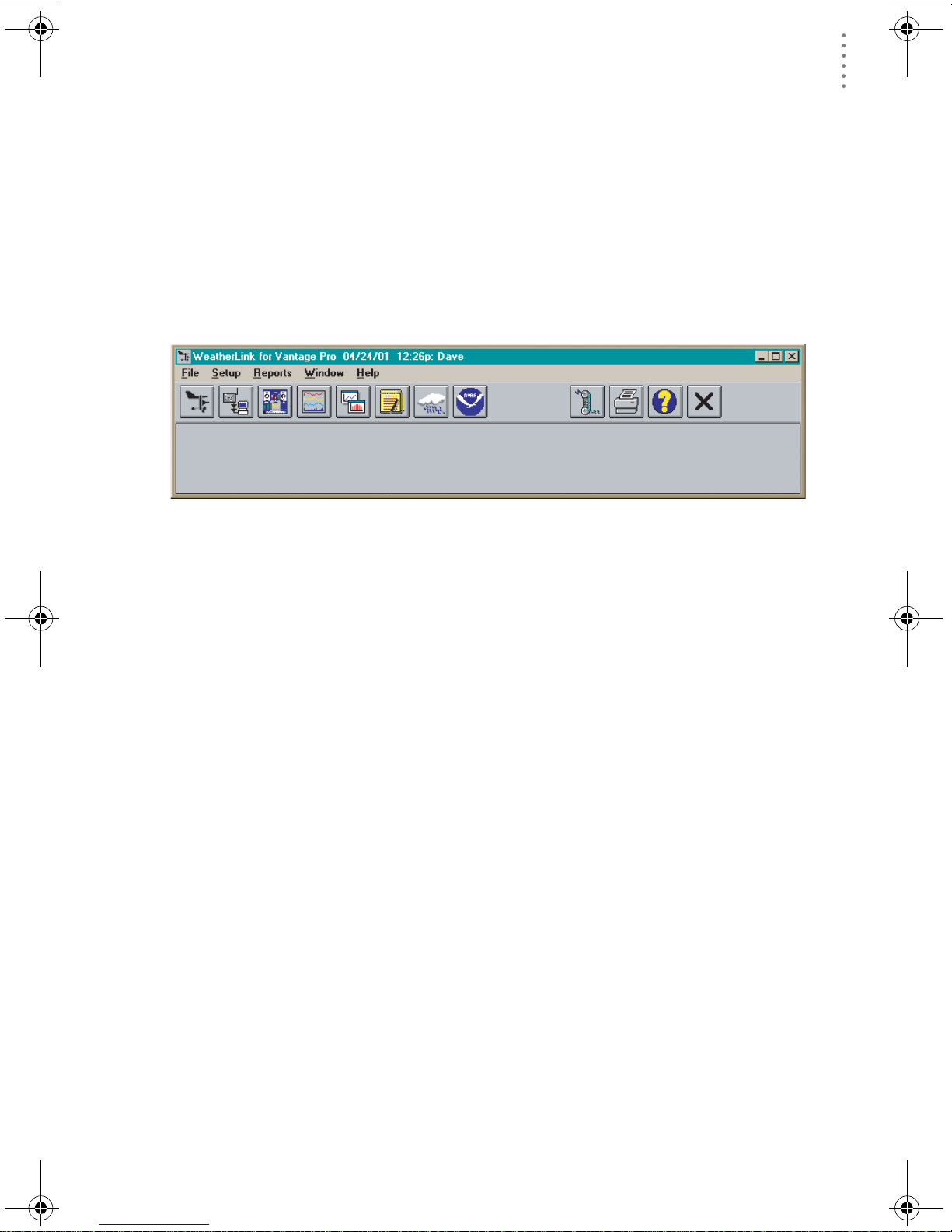
Open
Station
Bulletin
Window
Plot
Window
Toolbar Icons
Yearly
Rainfall
Alarm
Indication
On-Line
(Hang Up)
View
Help
Download
Strip Chart
Window
Main Program Window
Ctrl-A. . . . . . Set Alarms
Ctrl-B. . . . . . View Bulletin
Ctrl-C. . . . . . Station Configuration
Ctrl-G. . . . . . D egree-Days Report
Ctrl-H. . . . . . Hang Up
Ctrl-I. . . . . . . Serial Port Settings
Ctrl-J . . . . . . Automatic Download
Ctrl-K. . . . . . Walkthrough
Ctrl-L . . . . . . D ownload
Ctrl-O. . . . . . Open Station
Ctrl-P. . . . . . Print Active Window
Ctrl-Q. . . . . . Open Plot Window
Ctrl-R. . . . . . Yearly Rain Report
Ctrl-S. . . . . . Open Strip Charts
Ctrl-T . . . . . . Set Time
Ctrl-U. . . . . . Select Units
Ctrl-V. . . . . . View Download Log
Ctrl-W . . . . . Browse Database
Ctrl-X. . . . . . Auto Fax Settings
Ctrl-Y. . . . . . View Summary
Ctrl-Z . . . . . . Close Window
F1. . . . . . . . .Context-Sensitive Help
F2. . . . . . . . .Sunrise/Sunset Report
F7. . . . . . . . .NOAA This Month
F8. . . . . . . . .NOAA This Year
Database
Window
Hot Keys
This MonthÕs
NOAA Summary
Print
Window
Strip Chart Window
ESC . . . . . . . Halt redraw
Ctrl-M . . . . . Make Default
Ctrl-P. . . . . . Print Strip Chart
F1. . . . . . . . . Context-Sensitive Help
F3. . . . . . . . . Zoom In
F4. . . . . . . . . Zoom Out
Plot Window
ESC . . . . . . . Halt redraw
Ctrl-D. . . . . . Choose Date
Ctrl-M . . . . . Make Default
Ctrl-P. . . . . . Print Plot
F1. . . . . . . . . Context-Sensitive Help
F3. . . . . . . . . Zoom In
F4. . . . . . . . . Zoom Out
F9. . . . . . . . . Overlay Plots
F10. . . . . . . . Last Year Plot
Database Window
Ctrl-D. . . . . . Choose Date
Ctrl-N. . . . . . Add Note
Ctrl-P. . . . . . Print Records
Enter. . . . . . Edit Record
Delete . . . . . Delete Record
F1. . . . . . . . . Context-Sensitive Help
Yearly Rainfall Window
Enter. . . . . . Edit Year
Delete . . . . . Delete Year
Exit
Program
3465 Diablo Avenue, Hayward, CA 94545-2778 U.S.A.
510-732-9229 • Fax: 510-732-9188
E-mail: info@davisnet.com • www.davisnet.com
 Loading...