

Page 1
Product #7728
M
ULTI-PURPOSE
S
HELTER
The weather-resistant Multi-Purpose Shelter (MPS) may be used to protect a
number of system components from the elements.
CAUTION:
Please note that we have made every attempt to design and manufacture a safe product,
but Davis Instruments assumes no liability for any injury or damage caused directly or indirectly by the installation or use of this product.
C
OMPONENTS
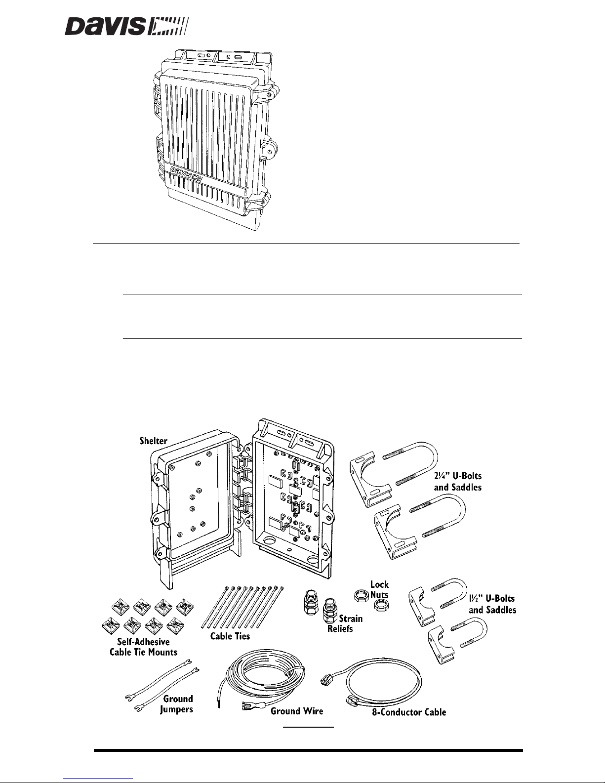
The MPS includes the following components. Please make sure that you have
all the listed components before continuing.
C
OMPONENTS
Page 2
Page 2 Multi-Purpose Shelter
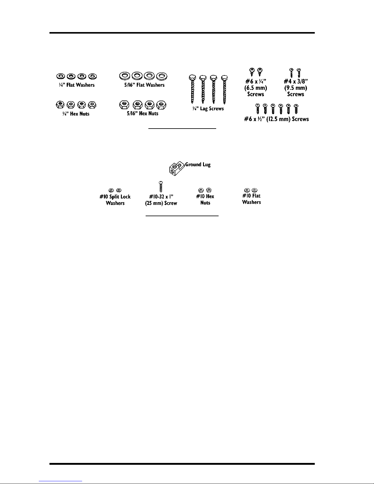
The hardware kit included with the MPS includes the following components.
Please make sure that you have all the components before continuing.
H
ARDWARE KIT COMPONENTS
The ground lug kit included with the shelter includes the following components. Please make sure that you have all the components before continuing.
G
ROUND
L
UG
K
IT
C
OMPONENTS
T
OOLS
AND
M
ATERIALS
N
EEDED
FOR
I
NSTALLATION
You may need some of the following tools and materials in order to install the
shelter.
✦
System Components
You will need the various system components you plan to install inside
the shelter. Some sample installation configurations are shown in “Sample MPS Configurations” on page 3.
✦
Medium Flat Head Screwdriver
✦
Medium Phillips Head Screwdriver
✦
Wrench or 3/8" Nut Driver
✦
Large Adjustable Wrench (1 3/8" Opening)
✦
Wire Cutter
✦
Wire Stripper or Knife
✦
Pliers
✦
Electrical Tape and/or Silicone Caulking
✦
Double-Sided Tape
Page 3

Attaching Cable Strain Reliefs Page 3
A
TTACHING
C
ABLE
S
TRAIN
R
ELIEFS
Attach both strain reliefs to the MPS as shown below. You will need to install
the strain reliefs before running cables into the MPS. Secur e the strain reliefs by
tightening the lock nuts. Do not tighten the compression nuts until you have
completed your installation (see “Securing the Cables” on page 12).
I
NSTALLING
S
TRAIN
R
ELIEFS
S
AMPLE
MPS C
ONFIGURATIONS
The illustrations below show three sample MPS installations. Consult the
installation manuals supplied with system components for wiring instructions.
Console, Sensor Interface Module (SIM), and Short-Range (SR) Modem
The illustration below shows an MPS installation which includes the console,
SIM, and SR Modem. When installing, make sure the indicated cable tie
mounts are attached to the MPS so the centers of the mounts are 1-1/4" (32
mm) from the bottom of the shelter.
C
ONSOLE
, SIM, SR M
ODEM
I
NSTALLATION
Page 4
Page 4 Multi-Purpose Shelter
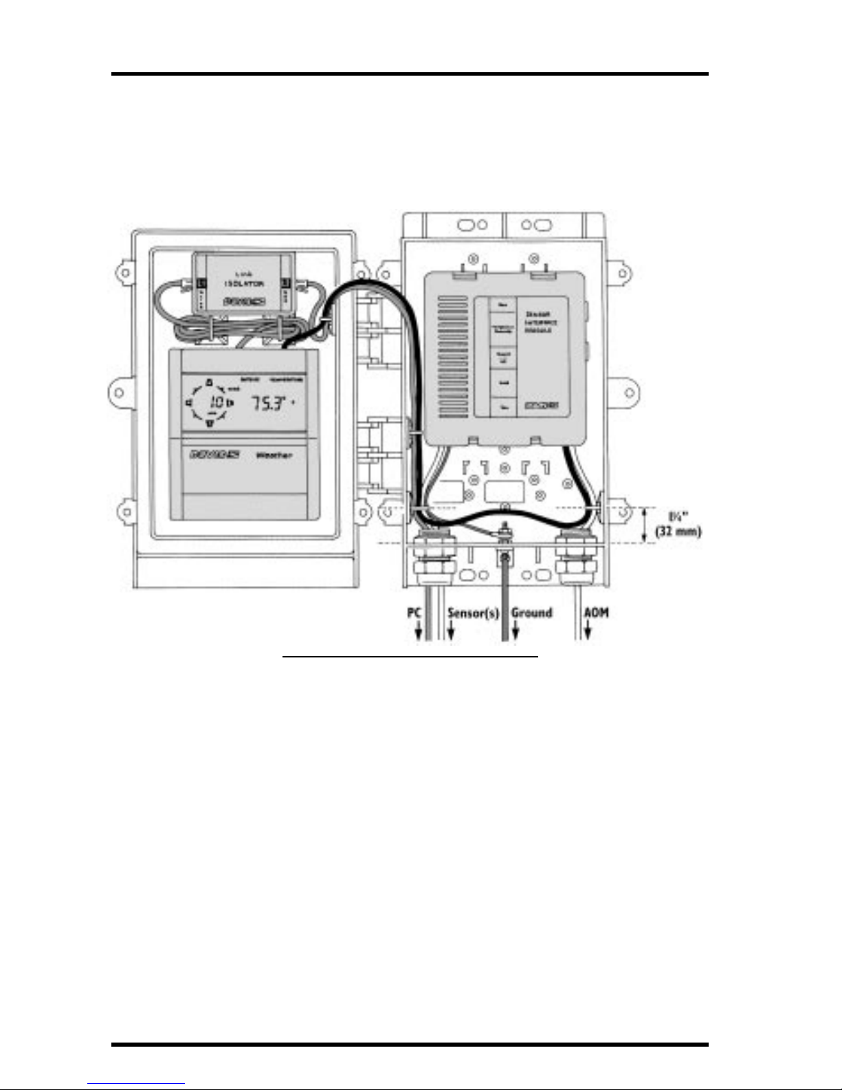
Console, Sensor Interface Module (SIM), and Link isolator
The illustration below shows an MPS installation which includes the console,
SIM, and Link Isolator. Make sure the indicated cable tie mounts are attached
to the MPS so the centers of the mounts are 1-1/4" (32 mm) from the bottom of
the shelter.
C
ONSOLE
, SIM,
AND
L
INK
I
SOLATOR
, I
NSTALLATION
Page 5

Installing Components into the MPS Page 5
Sensor Interface Module (SIM), Alarm Output Module (AOM), and Heater
The illustration below shows an MPS installation which includes the SIM,
AOM, and a heater. When installing, make sure the cable tie mounts are
attached to the MPS wall so the centers of the mounts are the indicated
distance from the bottom of the shelter, as shown below.
SIM, AOM,
AND
H
EATER
I
NSTALLING
C
OMPONENTS
INTO
THE
MPS
The sections below show where and how the various system components
install into the MPS. You will need to consult the installation manuals supplied
with each system component for instructions on wiring your installation. You
may want to wait until you have actually mounted the shelter (See “Mounting
the MPS” on page 9) before routing cables into the shelter.
Page 6

Page 6 Multi-Purpose Shelter
Installing a “Module”
You may install any of the following “modules” into the MPS: sensor interface
module, Protected Junction Box, Alarm Output Module (AOM), or Interface
Cable Adapter Module. Use the #6 x 1/2" (12.5 mm) self-tapping screws as
shown below. If you mount a module on the box’s cover , you will not be able to
ground it (the ground jumpers cannot reach the ground lug) so only install a
module on the door if it does not require grounding (such as the AOM). When
grounding “modules” installed in the shelter’s main box, use the ground
jumpers supplied with the MPS to connect to the shelter’s ground lug as
shown in “Grounding the Shelter and Components” on page 11.
I
NSTALLING
A
M
ODULE
Installing a Console
You may install the station console into the box or the cover, using the screws
shown below.
I
NSTALLING
A
C
ONSOLE
Page 7

Installing Components into the MPS Page 7
Installing a Small Junction Box
You may install the small junction box into the box or the cover, using the
screws shown below.
I
NSTALLING
A
S
MALL
J
UNCTION
B
OX
Installing Link Isolator
Use double-sided tape to attach the Link Isolator to the back wall of the MPS as
shown below.
I
NSTALLING
A
L
INK
I
SOLATOR
Page 8

Page 8 Multi-Purpose Shelter
Installing Short-Range Modem
Install the Short-Range Modem (SR Modem) into the MPS by using self-adhesive cable tie mounts and cable ties to secure the VELCRO
®
straps (provided
with the SR Modem) to the back wall of the MPS as shown below. Then use the
VELCRO straps to secure the SR Modem and adapter in place.
I
NSTALLING
A
SR M
ODEM
Installing a Heater
There are three possible heater locations. Install the shelter heater in one of
these locations, as shown below. Note that you must install the heater insulation blankets before installing the heater. Consult the shelter heater manual for
more complete instructions.
I
NSTALLING
H
EATER
I
NTO
MPS
Page 9

Mounting the MPS Page 9
Installing Terminal Blocks
Install terminal blocks into the MPS using the #4 x 3/8" (9.5 mm) self-tapping
screws (supplied with terminal blocks) as shown below.
I
NSTALLING
T
ERMINAL
B
LOCKS
M
OUNTING
THE
MPS
The instructions below will show you how to mount the shelter against a wall
or post, on a small pipe, or on a large pipe.
Mounting the Shelter on a Wall or Post
Attach the shelter to the mounting surface in the desired location using the lag
screws and 1/4" flat washers as shown below.
M
OUNTING
ON
A
W
ALL
OR
P
OST
Page 10

Page 10 Multi-Purpose Shelter
Mounting On a Pipe
Hold the rear of the shelter and the U-bolt saddles against the pipe and slide
the ends of the U-bolts through the holes in the saddles and shelter so that the
U-bolts wrap around the pipe as shown below. Secure the shelter using a flat
washer and hex nut on each end of the U-bolts. Tighten the hex nuts until the
shelter is firmly attached to the pipe.
✦
If mounting on a pipe with outside diameter between 3/4" and 1-1/4"
(19 mm and 31 mm) use the 1-1/2" U-Bolts and saddles, and the 1/4"
washers and hex nuts.
M
OUNTING
ON
A
S
MALL
P
IPE
✦
If mounting on a pipe with outside diameter between 1-1/2" and 2 3/8"
(38 mm and 60 mm) use the 2-1/4" U-Bolts and saddles, and the 5/16"
washers and hex nuts.
M
OUNTING
ON
A
L
ARGE
P
IPE
Page 11

Grounding the Shelter and Components Page 11
G
ROUNDING
THE
S
HELTER AND COMPONENTS
Attach the ground lug to the bottom of the MPS using a #10-32 x 1" (25 mm)
screw, washer, lock washer, and hex nut as shown below.
I
NSTALLING GROUND LUG
Run any ground jumpers from your system components to the ground lug and
attach using the other #10 washer, lock washer, and hex nut as shown below.
A
TTACHING GROUND JUMPERS TO GROUND LUG
Ground the MPS using the provided ground wire. If you anticipate heavy
surges, you may wish to use a heavier wire or multiple wires. Cut the ground
wire to the length required to reach from the MPS to a suitable ground, such as
Davis Instruments’ Grounding Kit (Product #7780). The ground wire should be
as short as possible. Strip both ends of the ground wire (remove the spade lug
if necessary) and insert one end into the ground lug. Secure in place by tightening the ground lug screw. Attach the other end to a suitable ground.
G
ROUNDING THE
MPS
Page 12

Product Numbers: 7728
Davis Instruments Part Number: 7395-114
Multi-Purpose Shelter
Rev. B Manual (7/7/99)
This product complies with the essential protection requirements of the EC EMC
Directive 89/336/EC.
© Davis Instruments Corp. 1997. All rights reserved.
VELCRO is a registered trademark of Velcro Industries, Manchester, NH.
S
ECURING
THE CABLES
After attaching all cables, tighten the compression nuts on the strain reliefs to
secure the cables and create a weather-resistant seal. If there is a large air space
around the cables, fill the space by wrapping cables in electrical tape and/or
sealing with silicone caulking.
SECURING CABLES
 Loading...