

Page 1
MOUNTING POLE KIT
INSTALLATION MANUAL
This manual covers use of the Mounting Pole Kit with the Integrated Sensor
TM
Suite (ISS) of the Vantage Pro
Davis Instruments sensor arrays, applying the principles shown here with the
ISS. On page 4, you may need to use a second U-bolt during step 2 .)
COMPONENTS
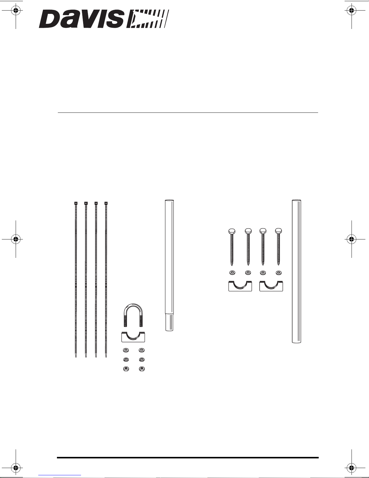
The mounting kit includes the following:
8" Cable Ties
system. (The kit can also be used with other
Support Tube
(19.5" long, swaged end)
5/16" x 3"
Lag Screws
5/16" Flat Washers
5/16" x 1-1/2"
U-Bolt
1-1/8" Saddle
5/16" Flat Washers
5/16" Lock Washers
5/16" Hex Nuts
1-1/8" Saddles
Extension Tube (21" long)
TOOLS AND MATERIALS NEEDED
In addition to the har dware s hown above, you may nee d some of the follo wing
tools and materials:
• Adjustable wrench
• Drill with 1/4" (6 mm) bit
Product # 7717
Page 2

INSTALLATION STEPS
r
• Secure one side or both sides of your ISS to the support tube, page 2
• Mount the extension tube, page3
• Install the support tube on the extension tube, page 4
SECURE THE ISS TO THE SUPPORT TUBE
The support tube is 19-1/2" (0.5 m) long, and has a swaged end. After you
secure one or both sides of your ISS to the support tube, this end will be
inserted into the top of the extension tube. Make sure the swaged end of the
support tu be is pointing downward as you secure the ISS (o r other sen sor
array).
The ISS comes with U-bolts, washers, and hex nuts for the purpose of mounting it on a pole. Consult your ISS Installation Manual for detailed instructions.
Remember, when mounting both sides together, that whichever side of the
ISS is mounted first, the U-bolt from the opposite side ALSO must be placed
around the pole before you tighten an ything. (If i t is not, there is no way to
slide it in later.)
1/4" Hex Nut
1/4" Lock Washer
Backing Plate
U-Bolts
Anemometer's Mounting Base
Rain Collector Side's Mounting Base
1/4" Flat Washer
1/4" Lock Washe
1/4" Hex Nut
If you wish to put the anemometer higher than the rain collector side of your
ISS on the support tube, follow the instructions in the ISS Installation Manual
for mounting each side separately.
The anemometer arm must point northward or you will have to re-orient the
wind vane after mounting. (As shown in Appendix C in the ISS manual.)
Page 2 Mounting Pole Kit
Page 3

MOUNT THE EXTENSION TUBE
The extension tube is 21" long (and does not have a swaged end.)
1. In a fence-post or other
flat vertical surface, drill
two holes, using one of
the 1-1/8" saddles as a
guide.
2. Drill another set of holes
at leas t 12" (0.3 m) away
from the first holes.
3. Using the 5/16" flat washers and lag screws, secure
the saddles against the
extension tube and into
the post.
4. Ti g hten the lag screws
until the tube will not
slide up or down no matter how hard you try to
move it.
ISS (both sides)
Support Tube
(swaged end)
12"
minimum
Saddle
Flat Washers
Lag Screws
Extension Tube
(21" long, no swaged end)
Mount the Extensio n Tube Page 3
Page 4

INSTALL THE SUPPORT TUBE ON THE EXTENSION TUBE
1. Insert the swaged end of the s up p ort tub e in th e ope n top of the ex ten sion tube.
2. Place the U-bolt provid ed in the mou n ting pole kit around the tubes where th ey
overlap. Secure with flat washers, lock washers, and hex nuts as shown in the illustration.
3. Tighten the hex nuts quite firmly, until the U-bolt begins to dent the tubing
slightly.
4. Use the 8" ca ble tie to secure cable as needed.
ISS
Support Tube
Lock
Washers
Saddle
Hex
Nuts
Product Number: 7717
Davis Instruments Part Numb er : 7395 .298
Mounting Pole Kit Installation Manual
Rev. A Manual (January 17, 2001)
Copyright © Davis Instruments Corp. 2001. All rights reserved.
Vantage Pro is a trademark of Davis Instruments Corp.
Flat
Washers
Extension
Tube
(swaged end)
2-1/2"
tighten until U-bolt
dents the tubing slightly
3465 Diablo Avenue, Hayward, CA 94545-2778 U.S.A.
510-732-9229 • Fax: 510-732-9188
E-mail: info@davisnet.com • www.davisnet.com
 Loading...