

Page 1

Product # 7846 & 7848
L
EAF
W
ETNESS
S
ENSOR
S
TANDARD
& I
NDUSTRIAL
I
NSTALLATION MANUAL
The leaf wetness sensor enables the GroWeather™ to detect the presence of
surface moisture on foliage and calculate the duration of wetness. When moisture is present, the sensor detects an electrical resistance change between the
gold-plated elements of the grid. This is displayed by the GroWeather console
as a value between 0 (dry) and 15 (wet). Using the GroWeatherLink
®
software,
you may select your own wetness threshold; the software will then calculate
leaf-wet hours.
C
OMPONENTS
The leaf wetness sensor includes the following components. Please make sure
you have all listed components before continuing.
✦
Leaf Wetness Sensor with
attached mounting bracket
The standard version of
the sensor includes an
attached 40’ (12 m) cable.
The industrial version
includes a 16’ (5 m) cable.
✦
Installation Hardware Kit
✦
One 1-1/2" U-Bolt
✦
Two 1/4" Flat W ashers
✦
Two 1/4" Hex Nuts
✦
Two #8 Wood Screws
✦
Two #8 x 3/4"
Machine Screws
✦
Four # 8 Flat Washers
✦
Two # 8 Lock Washers
✦
Two # 8 Hex Nuts
Page 2

Page 2 Leaf Wetness Sensor
T
OOLS
AND
M
ATERIALS
N
EEDED
You may need some of the following tools and materials in order to complete
your installation. Please be sure you have everything you need before beginning.
✦
Medium Phillips Screwdriver
✦
Wrench
✦
Drill with 7/32" (5.5 mm) Drill Bit
To drill holes in the Sensor Mounting Arm (SMA) if installing on an
older version of the SMA.
✦
7/16" Wrench or Adjustable Wrench
To tighten hex nuts if installing on a pipe.
T
ESTING
THE
S
ENSOR
You may test the sensor before you install it or you may test it after installing it.
The instructions below provide a quick description of the suggested test procedure.
1. Attach the sensor cable to the connector S3 on the sensor interface module (SIM).
Consult the installation manual for instructions
2. Press the appropriate key(s) to make sure you are getting a leaf wetness reading on
the console.
Consult the GroWeather manual for instructions on displaying leaf wetness.
3. Drop or spray water onto the sensor and make sure the reading changes.
Page 3

Installing the Sensor Page 3
I
NSTALLING
THE
S
ENSOR
Follow the instructions in this section to install your sensor. Before you begin,
consult the System Installation manual for instructions on labeling the leaf wetness sensor cable.
Typical Standard Installation
The illustration below shows typical standard leaf wetness installation. The
sensor cable attaches to connector S3 on the sensor interface module (SIM).
T
YPICAL
S
TANDARD
I
NSTALLATION
Page 4

Page 4 Leaf Wetness Sensor
Typical Industrial Installation
The illustration below shows typical industrial leaf wetness installation. The
sensor cable attaches to connector S3 on the sensor interface module (SIM).
T
YPICAL
I
NDUSTRIAL
I
NSTALLATION
Page 5

Installing the Sensor Page 5
Mounting the Sensor on the Sensor Mounting Arm
Follow the instructions below to mount the sensor on the Sensor Mounting
Arm (SMA).
1. If no holes exist on the side of the mounting arm, you need to mark the location of the
two holes on the mounting bracket and drill holes through the SMA in these locations
using a 7/32" (5.5 mm) drill bit. If you are not using the Sensor Tilting Bracket, you
may use one of the holes designated for the bracket for the leaf wetness sensor.
Early versions of the SMA did not include holes for the leaf wetness sensor.
If your SMA includes holes for the leaf wetness sensor, you may skip this
step.
2. Attach the leaf wetness sensor to the SMA using the #8 x 3/4" machine screws, # 8
flat washers, # 8 lock washers, and # 8 hex nuts as shown below.
M
OUNTING
ON
THE
S
ENSOR
M
OUNTING
A
RM
Page 6
Page 6 Leaf Wetness Sensor
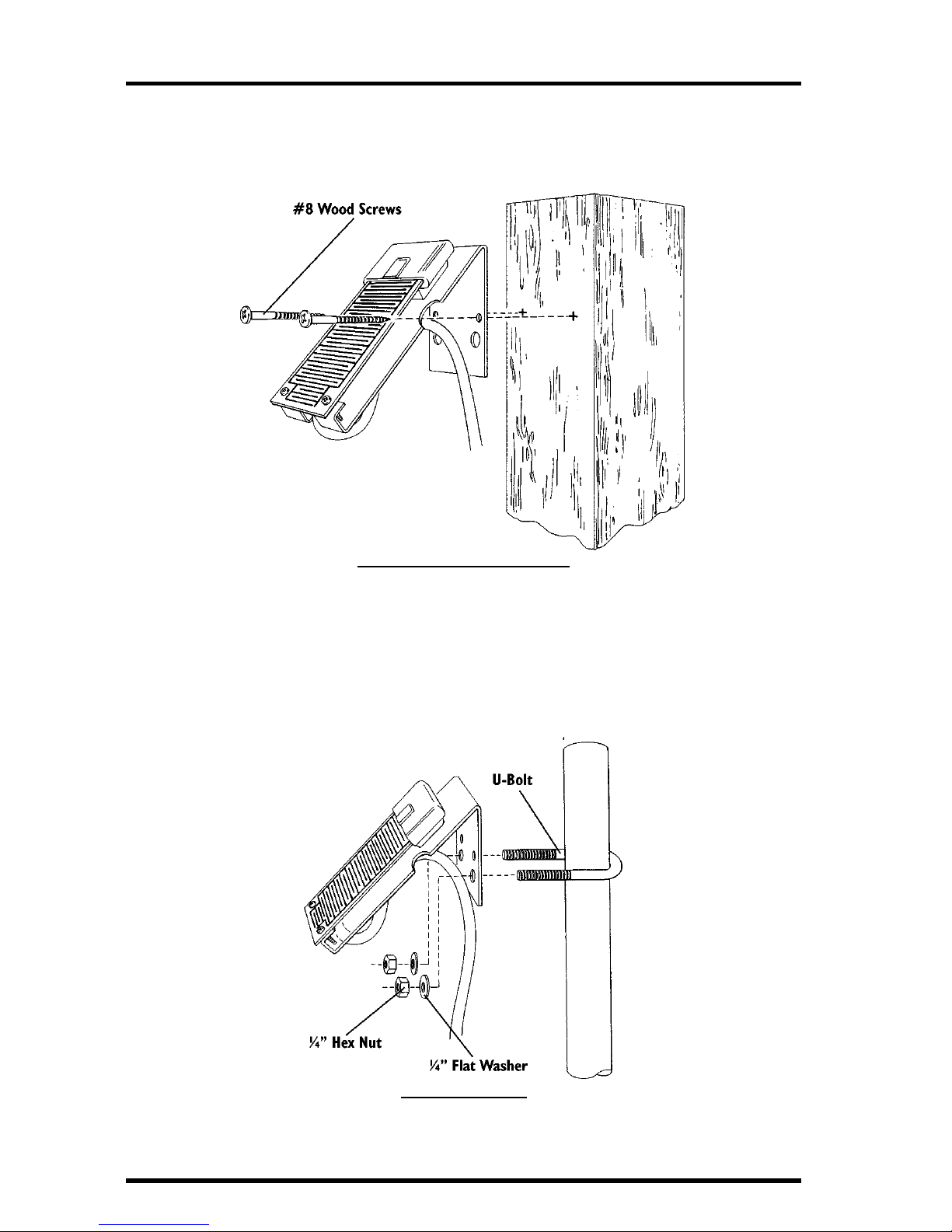
Mounting the Sensor Against a Wooden Surface
To mount the sensor against a wooden surface, secure the sensor to the surface
using the #8 wood screws as shown below.
M
OUNTING
ON
A
W
OODEN
S
URFACE
Mounting the Sensor on a Pipe
To mount the sensor on a pipe, stake, or pole with outside diameter between
1" and 1-1/4" (25 mm and 31 mm), secure the sensor to the pipe using the 1-1/
2" U-bolts, 1/4" flat washers, and 1/4" hex nuts as shown below. Use a 7/16"
wrench or adjustable wrench to tighten the hex nuts.
M
OUNTING
ON
A
P
IPE
Page 7

Technical Support Page 7
T
ECHNICAL
S
UPPORT
Before calling Technical Support (1-510-732-7814), carefully check all cable connections from the sensor to the console. Cable connections account for a large
portion of the potential problems. Connections should be firmly seated in the
jacks and plugged in straight. If you think a connection may be faulty, try jiggling the cable while looking at the display. If a reading appears intermittently
on the display as you jiggle the cable, the connection is faulty.
Page 8

Product Numbers: 7846 & 7848
Davis Instruments Part Number: 7395-110
Leaf Wetness Sensor, Standard and Industrial
Rev. D Manual (7/7/99)
This product complies with the essential protection requirements of the EC EMC
Directive 89/336/EC.
© Davis Instruments Corp. 1996. All rights reserved.
 Loading...