

Page 1
USER
MANUAL
Gateway
and Node
™
Product numbers 6801, 6802A and 6810
R
Davis Instruments, 3465 Diablo Avenue, Hayward, CA 94545-2778 U.S.A. • 510-732-9229 • www.davisinstruments.com
Page 2
FCC Part 15 Class B Registration Warning
This equipment has been tested and found to comply with the limits for a Class B digital
device, pursuant to Part 15 of the FCC Rules. These limits are designed to provide
equipment generates, uses, and can radiate radio frequency energy and, if not installed and used in
accordance with the instructions, may cause harmful interference to radio communications.
However, there is no guarantee that interference will not occur in a particular installation.
This device complies with part 15 of the FCC Rules. Operation is subject to the following two
conditions: (1) this device may not cause harmful interference, and (2) this device must accept any
interference, including interference received, including inference that may cause undesired operation.
This device complies with Industry Canada license-exempt RSS standard(s). Operation is subject to
the following two conditions: (1) this device may not cause interference, and (2) this device must
accept any interference, including interference that may cause undesired operation of the device.
Le présent appareil est conforme aux CNR d'Industrie Canada applicables aux appareils radio
exempts de licence. L'exploitation est autorisée aux deux conditions suivantes: (1) l'appareil ne doit
pas produire de brouillage, et (2) l'appareil doit accepter tout brouillage radioelectrique subi, même si
le brouillage est susceptible d'en compromettre le fonctionnement.
The antenna used for this transmitter must be installed to provide a separation distance of at least 20
cm from all persons and must not be co-located or operating in conjunction with any other antenna or
transmitter.
If this equipment does cause harmful interference to radio or television reception, which can be
determined by turning the equipment on and off, the user is encouraged to try to correct the
interference by one or more of the following measures:
• Reorient or relocate the receiving antenna.
• Increase the separation between the equipment and receiver.
• Connect the equipment into an outlet on a circuit different from that to which the receiver is
• Consult the dealer or an experienced radio/TV technician for help.
Changes or modification not expressly approved in writing by Davis Instruments may void the warranty
and void the user's authority to operate this equipment.
FCC ID: IR2DWW6800, IR2DWW6810, RI7LE910C1NS, or R17HE910.
IC: 3788A-6800, 3788A-6810, 5131A-LE910C1NS or 5131A-HE910.
reasonable protection against harmful interference in a residential installation. This
connected.
EC-Declaration of Conformity
Directive 2014/53/EU (RED Directive)
Manufacturer/responsible person: Davis Instruments
Hereby declares that the products:
6801, 6802A, and 6810
Comply with Directive 2014/53/EU. The full text of the EU Declaration of Conformity is on our website at
https://www.davisinstruments.com/legal
Power Output: see page 25: Specifications
The technical documentation relevant to the above equipment will be held at:
Davis Instruments at 3465 Diablo Ave, Hayward CA 94545
0
Compliance Engineer
3465 Diablo Ave., Hayward, CA 94545 USA
Page 3
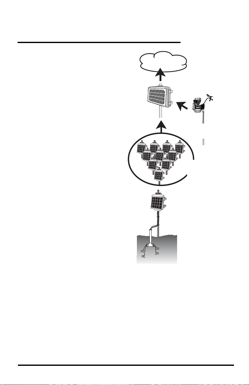
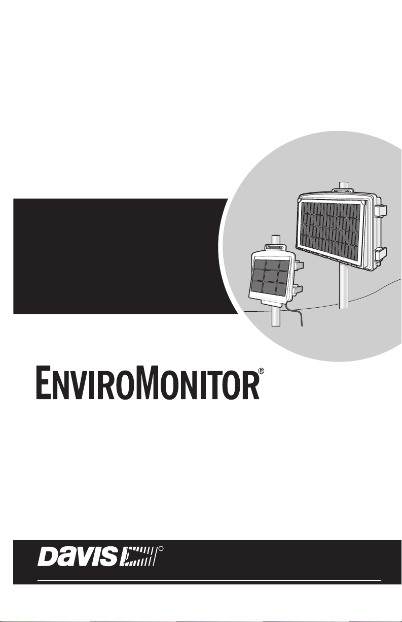
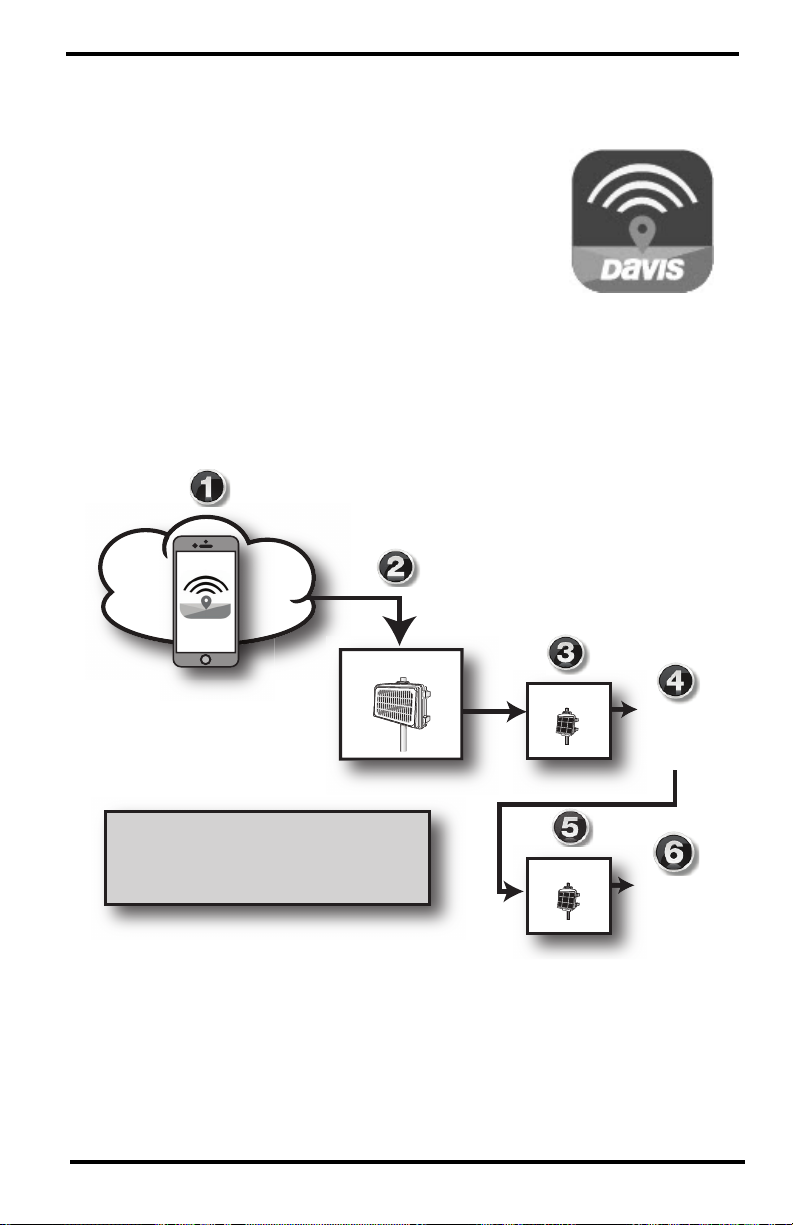
Welcome to Your EnviroMonitor System
An EnviroMonitor System
includes a Gateway and a number
of Nodes, each with up to four
sensors that form an advanced
mesh network operating at 902 928 MHz (868 MHz in the EU).
The Nodes transmit the sensor
data to a “mesh parent,” either the
Gateway or another Node. The
Gateway then sends the data via
cellular connection to
WeatherLink.com.
EnviroMonitor can be customized
for different sized installations.
Each Gateway can receive 20 or
more Nodes. Additional Gateways
can be added to your account to
receive data from another set of
Nodes.
A Davis cabled GroWeather
Sensor Suite can also be plugged
into the Gateway.
This manual will show you how to
set up both the EnviroMonitor
Gateway and Nodes. If you are
just installing a Node and have
already installed the Gateway, you
can skip to page 12:
and Sensors
.
Set Up Nodes
WeatherLink.com
1 Gateway
™
20+
Nodes
per
Gateway
0-4 Sensors
per Node
Cabled
GroWeather ISS
(optional)
The steps for setting up your EnviroMonitor system:
1. Plan: What sensors do you need and where? Decide where you will install the
Gateway and Nodes. See page 2:
2. Power up your Gateway. See page 7:
Planning Your System.
Power-up and Connect your Gateway.
3. Connect your Gateway to WeatherLink.com with the EnviroMonitor app.
4. Mount the Gateway. See page 9:
5. Power up the Node. See page 13:
Mount the Gateway.
Power-up and Connect the Node.
6. Connect the Node to the Gateway with the EnviroMonitor app.
7. Mount the Node. See page 16:
Mount the Node.
8. Add and Install the sensors with the EnviroMonitor app.
1
Page 4

Planning Your System
After determining which sensors you want and where you want to install them, make
sure you have the correct number of Nodes to support those sensors.
The maximum distance between two Nodes and a Gateway and a Node will vary
depending on many factors including environment, height, terrain, and RF noise.
To get optimal transmission range:
• Ideally, locate the devices with unobstructed lines of sight between them. A large
hill or large metal barrier will block signals. If transmitting under a canopy or in
an orchard, range will be reduced.
• Mount the devices as high above the ground or the highest crop height as
possible. The higher they are mounted, the longer the transmission distance.
• Try to mount the Gateway on a rooftop or pole so that it has a good “view” of the
area where the Nodes will be mounted.
6 feet
1.8 m
300 - 500 ft
90 -150 m
1700 - 2000 ft
515 - 610 m
4 feet
1.2 m
Orchard, under canopy
8 feet
™
2.4 m
6 feet
1.8 m
Note: This illustration shows how installation height affects general transmission distances
under ideal conditions. Many variables affect transmission distance. Results will vary
based on environmental conditions.For longer transmission distance, add a Long
Range Antenna to the Gateway and/or Nodes. See page 21:
1800 - 2400 ft
545 - 730 m
Line of sight, above highest
crop height or open eld
Line of sight, above highest
crop height or open eld
2400 - 4000 ft
730- 1220 m
Line of sight, above highest
crop height or open eld
™
Appendix A: Adding a
10 feet
3 m
Long Range Antenna.
2
Page 5
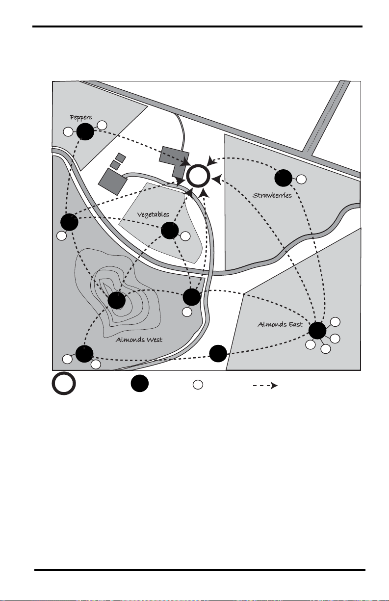
Make a Sketch
It is helpful to make a sketch of your installation to get an idea of where the
Gateway and Nodes should go.
SAMPLE FARM
Peppers
S
N
S
N
S
N
Vegetables
N
N
N
Almonds West
N
N
S
S
G
G
Gateway Node Sensor Transmission Mesh
N
Davis Rd.
G
G
Strawberries
S
Diablo Creek
N
S
N
S
Almonds East
N
S
Hwy. 10
N
S
S
S
S
3
Page 6
Tips for Siting the Gateway and Nodes
Siting the Gateway
• The Gateway should be mounted where it has the strongest cellular connection
and a clear, open “view” of the sky with good sunlight for the solar panel.
™
™
• You may plug a cabled Vantage Pro2 sensor suite, such as GroWeather,
directly into your Gateway. If you do, you will need to choose a location that is
within reach of the sensor suite’s included 100’/30 m (extendable up to 1,000’/
300m) cable. See page 11:
Add a Vantage Pro2 Sensor Suite (optional).
Cabled
GroWeather
100 ft./ 30 m cable
(extendable to 1,000 ft/ 300 m)
Gateway
Note: The radio in the Gateway is not compatible with the radio in wireless Vantage Pro2
stations.
4
™
Page 7

Siting the Nodes
• Ideally, the mesh network will be most effective at “self healing” any
temporarily impaired transmission paths if each Node has more than one way
to reach the Gateway. While the system is designed to handle a mesh, a “star”
or nodes in single lines, it is a good idea whenever possible to site each node so
that it is within transmission distance of either two (or more) other Nodes, or
the Gateway and another Node. A Node can even be installed simply to
transmit data from more distant Nodes to the Gateway, without any sensors
installed in it. By planning the system’s “transmission mesh,” data can be
relayed in from the most remote corner of your installation.
™
The best installations allow Nodes to
transmit to more than one Node or to
a Node or Nodes and the Gateway.
• Nodes can also be used to transmit data around or over obstacles, such as hills.
™
™
Get around an obstruction by using a Node with no sensors as a relay.
5
Page 8
Set up your Gateway
Contents of Gateway (6802A shown)
Cellular
Antenna
Solar Power Cable
Hardware kit
Main Power Jack
Main Power Cable
Power/Cell
Status LED
Recessed Touch Pads
DID: AA123456789
R
Battery Cables
BLE
Status LED
Device ID
Mesh
Antenna
Jack for Cabled
GroWeather
Sensor Suite
(Optional)
2 Large
&
2 Small
U-Bolts
1/4" Lock Washers
1/4" Hex Nuts
Backing Plates
(Disregard two #6 x 3/8 Screws)
1/4" x 1 1/4" Lag Screws
Oval split grommet
8’ Cable for
Cabled GroWeather (optional)
Gateway Requirements & Tools
• 2G/3G GSM (6801) or LTE (6802) cellular network (in the US) coverage in the
area where the Gateway will be installed
• Smartphone
• Mounting pole or post
• Wrench
• Power drill if using lag screws
6
Page 9
Power-up and Connect your Gateway
AAA
A
Install the EnviroMonitor App
1. Install the EnviroMonitor app on your Smartphone.
Find the app by searching for the Davis
EnviroMonitor app in the iOS App Store or Google
Play Store.
The EnviroMonitor app will guide you through
creating an account on WeatherLink.com, adding
the Gateway, adding Nodes to the Gateway, and
adding sensors to the Node.
Add Gateway
Open the App to create your
he App to create
account on WeatherLink.com
™
EnviroMonitor App:
Guides you through these steps
EnviroMonitor App
Add Node 1
Add Node 2
Add Sensor 1
Add Sensor 2
Add Sensor 3
Add Sensor 4
Add Sensor 1
Add Sensor 2
Add Sensor 3
Add Sensor 4
7
Page 10

Power up your Gateway
S
1. Remove all cardboard and packing materials from inside the Gateway.
2. Connect the battery.
The Gateway is shipped with one battery cable (the red, or positive cable)
disconnected to prevent battery drain. Connect the red cable to the red
terminal.
Red Cable
IMPORTANT: If putting your Gateway into storage, disconnect the red cable.
3. Plug the main power cable into the jack.
Main Power Jack
Main Power Cable
8
Page 11

Connect the Gateway to WeatherLink.com
1. Make sure the Bluetooth (BLE) function on your smartphone is on.
2. Open the app and choose Sign Up to create an account, or Log in if you have
already created an account
3. Tap Add Gateway.
4. Bring the phone close to the Gateway.
5. If a message appears that an upgrade has been detected, select Upgrade.
Upgrading can take several minutes.
Tip: The LED flashes to show that the Gateway’s BLE is on. If it is not flashing, press the
recessed touch pads. See the illustration on page 6: Contents of Gateway (6802
shown) for the location of the recessed touch pads.
6. The LED will turn solid blue when the Gateway has successfully connected to
your smartphone.
7. Once connected, enter a name for this Gateway. Choose a name based on the
use or location so you can easily identify this Gateway if you install others.
8. Follow the prompts to finish adding the Gateway.
9. Once done, you will be prompted to add a Node. Before adding a Node,
however, you should mount the Gateway.
Mount the Gateway
Confirm Cellular Strength
The best way to determine cellular connection is to take the Gateway to your
proposed location and use the EnviroMonitor app to see the signal strength.
In the app, choose this Gateway. Open the Menu icon in the upper right
corner. Choose Connection.
• If the app shows cell connection, but the RSSI is less than 4, the cellular signal
is present but weak. It may be strong enough to work, but it would better to find
a location with a stronger signal:10 or higher is preferable. If there are large
trees or buildings nearby, they may be obstructing the signal between the
Gateway and cell tower. Try changing the location to avoid the obstruction. If
your selected location is in a low spot, try moving to a higher location.
Tip: If the app shows no cellular signal at the chosen location, try a second choice
location. Remember to choose Refresh in the app and wait a few minutes to see the
strength at the new location.
Tip: Mounting the Gateway may be easier if done by two people.
The Gateway can be mounted on a pole or a flat surface such as a wall or post.
It is important that the Gateway be mounted so that the solar panel gets the greatest
amount of sunshine: the solar panel should be facing south (in the Northern
Hemisphere) or north (in the Southern Hemisphere).
9
Page 12

Tip: While south is generally appropriate for the Northern Hemisphere (and north in the
Southern Hemisphere), your goal is to maximize direct sunlight on the solar panel. If
your location does not have a full sunrise-to-sunset exposure arc when the panel
faces south, you should face your solar panel toward a point midway in the existing
arc to maximize panel charging.
Mounting on a Flat Surface
Attach the Gateway to the mounting surface in the desired location using the lag
screws and backing plates as shown below. Use a pencil or a center-punch to mark
the location of the pilot hole.
Mounting On a Pole
Mount the Gateway onto a pole with the U-bolts, backing plates, washers, and hex
nuts provided.
Note: Use the smaller U-bolts on a pole with an outside diameter of 0.84'' to 1.84'' (21 mm
to 47 mm). For mounting on square perforated tubing or larger diameter poles up to
1.94'' (49 mm) outside diameter, use the larger U-bolts.
10
Page 13

Add a Vantage Pro2 Sensor Suite (optional)
Add a cabled Vantage Pro2 integrated sensor suite (ISS), such as GroWeather
(product number 6820C), to your system, to get rain, wind, temperature, humidity
and solar radiation data to the Gateway.
Note: Wireless Vantage Pro2 integrated sensor suites are not compatible with this Gateway,
1. Open the Gateway door.
2. Remove the plug from
one of the holes in the
bottom of the Gateway
and run the sensor suite
cable up through it.
Cabled ISS
Jack
3. Outside the shelter, wrap
a split grommet with an
oval hole (included in
hardware kit) around the
cable and push the
grommet securely into
Split
Grommet
ISS Cable
the hole. Plug the cable
into the ISS cable jack.Close the door.
4. Secure the sensor suite cable to the post or pole with the included zip ties. Do
not use staples to secure the cable.
Note: If you are mounting the Gateway and the sensor suite together, you may find that the
100’/30m cable that comes with the sensor suite is too long. You may use the
included 8’/2.4 m cable. If you use this shorter cable, pay special attention to
preventing the sensor suite from shading the solar panel on the Gateway. (See
below.) Davis also has two other cable lengths available for purchase: 40’/12m,
(product no: 7876-040) and 200’/61m (product no. 7876-200).
If your installation is between 0° and 45°
latitude, North or South, and you mount the
Gateway and a Vantage Pro2 sensor suite on the
same pole, it is important to make sure the
sensor suite does not shadow the Gateway’s
solar panel at midday, especially in the summer.
If possible, mount the sensor suite and Gateway
Cabled
GroWeather
At least 4 ‘ (1.2m)
apart to prevent
shading of solar
panel.
so that they are at least 4 feet (1.2 m) apart. You
can also rotate the Gateway 45° to the east or
Gateway
™
west (depending on your location). If you do
rotate the Gateway, you may need to return it to
face south (Northern Hemisphere) or north
(Southern Hemisphere) in the winter.
You can also add a Davis Angle Shelter Bracket, product number 6671, which will
increase the Gateway’s tilt to 30
°.
11
Page 14

Set Up Nodes and Sensors
Contents of Node
Lithium Battery
Installed
Battery
Compartment
Door
D-Cell Battery
Compartment
(batteries not included)
Hardware Kit
Solar Panel Jack
Remove Battery
Pull Tab
Door Tabs
Solar Panel Cable
Sensor
Ports
Bluetooth
status LED
Mesh
status LED
Mesh
Antenna
Connector
for Internal or
External Antenna
12
2 Large
&
2 Small
U-Bolts
1/4" Lock Washers
1/4" Hex Nuts
Backing Plates
Green 6-Wire
Sensor Connectors
Cable Ties
Adhesive
Mounts
Precision Screwdriver
1/4" x 1 1/4"
Lag Screws
#6 x 3/8 Screws
(disregard)
Page 15

Requirements & Tools for Installation of Nodes and Sensors
A
A
A
A
• Included precision/miniature slotted screwdriver; ideal
size: 2.5 mm or 3/32”; see actual size image of screw
head and screwdriver blade at right.
• Four D-cell batteries
• Smartphone with EnviroMonitor app installed. See page 7:
EnviroMonitor App
.
Install the
• Wire cutter/stripper and wrench
• Mounting pole or post
Note: You should install Nodes starting with the Node that will be closest to Gateway, then
working outward to the Node furthest from Gateway. This allows each Node to
establish a connection with the Gateway or a Node that has already been installed.
Power-up and Connect the Node
Make sure the EnviroMonitor app has been installed on the smartphone you will
be using to install the Node. It will guide you through adding Nodes to the
Gateway that has already been installed.
Add Gateway
Open the App to create your
he App to create
account on WeatherLink.com
™
Add Node 1
Add Sensor 1
Add Sensor 2
Add Sensor 3
Add Sensor 4
EnviroMonitor App:
Guides you through these steps
Add Node 2
Add Sensor 1
Add Sensor 2
Add Sensor 3
Add Sensor 4
Power Up the Node: See illustration on page 12: Contents of Node.
1. Remove the D-cell battery compartment door and install 4 D-cell batteries
according to the + and - marks in the battery compartment. The Node will
power up. The mesh status LED will indicate connection. Replace the door.
IMPORTANT: Install the D-cell batteries FIRST. Make sure they are firmly installed and not
tilted outward. The battery compartment door prevents the D-cells from vibrating
loose; be sure to reinstall it correctly.
2. Remove the battery pull tab from the lithium battery and make sure the battery
is firmly in place.
3. Plug in the solar panel cable.
13
Page 16

Connect Node to Gateway
1. Take the Node and smartphone to the general location in which you wish to
install your Node. Make sure the phone’s Bluetooth (BLE) is on.
2. Open the app on the smartphone.
3. Open the door of the Node. (This turns the Node’s BLE on.) The BLE status
LED will blink blue. See the illustration on page 12:
Contents of Node.
4. In the app, select the Gateway to which this Node will send its data.
5. Tap Add Node.
6. Bring the phone close to the Node.
7. Follow the prompts in the app as it finds the Node and connects it to the
Gateway. This transmits the Gateway’s identifying information to the Node
and allows its data to be received by the Gateway. Having specific
identification for each Gateway/Node pair allows you to have multiple
Gateways without cross transmission.
Using the app, you will be see this Node’s serial number appear on the list for
the Gateway.
You will know the Node has found its “mesh parent” (a Gateway or another
Node) when you see the BLE status LED go solid blue. If it cannot “find” its
parent, try moving the Node to a different location. If the location of the Node
cannot be changed, consider installing another Node closer to the parent, to
act as a repeater. It does not need to have any sensors installed.
When the connection is complete, the mesh status LED will turn solid green.
See the illustration on page 12:
Contents of Node.
Install the Sensor(s)
The list of sensors your EnviroMonitor system supports is constantly growing.
Check www.davisinstruments.com/em-sensors for the current list.
Note: Wiring diagrams for each sensor are shown in the EnviroMonitor app.
Each Node has four sensor ports.You can install the sensors before or after
mounting the Node. For example, if you plan to mount the node on a tower, you
will want to install the sensor first.
1. Install the sensor in the environment per the
manufacturer’s instructions, making sure the
sensor is installed within cable reach of the Node
when it is mounted.
2. On your smartphone, open the EnviroMonitor
Wire each
sensor as
directed in
the App
app and select this Node. Tap Add Sensor. From
the menu, first select the sensor type, then the
specific sensor. Follow the wiring diagram in the
2
1
app to correctly wire the sensor into one of the
green 6-wire sensor connectors. Using a 2.5mm
(3/32”) precision slotted screwdriver, loosen the
appropriate screws and insert the bare wires.
3. Tighten the screws very tight.
14
6
5
4
3
Page 17

4. Insert the 6-wire sensor connector into the sensor port indicated by the app.
Make sure it is aligned properly and not offset.
Note: If the Davis sensor has an RJ-plug on its
cable, use the Davis RJ Adapter, product
number 6860. Or, you can remove the plug
and strip the wires.
Try not to strip the covering back so far
that the bare wires can touch each other
when the connector is plugged in, but make sure the clamp in the sensor port is
closing on wire, not plastic. (About 1/4” [6.4 mm] of exposed wire is ideal.)
RJ Adapter,
#6860
5. Run the sensor cable down and out of the box through the bottom. Make sure
it will be enclosed by the foam when the Node door is closed.
6. When all sensors are installed, close the Node door, making sure all cables are
against the foam and not the hard plastic of the door. Use included zip ties and
adhesive mounts if desired.
Adhesive
Mount
Make sure
cables exit
against
the foam.
Foam
Note: Make sure none of the
sensor cables are pinched in
the door; especially the cable
on the the sensor installed in
Port 1.
15
Page 18

Mount the Node
The Node can be mounted on a pole or a flat surface such as a wall or a wooden
post.
It is important that the Node be mounted so that the solar panel gets the greatest
amount of sunshine -- the solar panel should be facing south (in the Northern
Hemisphere) or north (in the Southern Hemisphere).
Tip: Mounting the Node may be easier if done by two people.
Mounting On a Fence Post or Pole
Mount the Node onto a fence post or a pole using the U-bolts, backing plates,
washers, and hex nuts provided.
Note: Use the smaller U-bolts on a pole with an outside diameter of 0.84'' to 1.84'' (21 mm
to 47 mm). For mounting on square perforated tubing or larger diameter poles up to
1.94'' (49 mm) outside diameter, use the larger U-bolts.
16
Page 19

Mounting on a Flat Surface
®®
Attach the Node to the mounting surface in the desired location using the lag
screws and backing plates as shown below. Use a pencil or a center-punch to mark
the location of the pilot hole.
Note: To increase transmission range from Node to Gateway or Node to Node, you may
replace the internal mesh antenna with an external Long Range Antenna. See page
21: Appendix A: Adding a Long Range Antenna
Manage Your Data
Log on to WeatherLink.com to view and manage your data.
You can also use view and manage your data on your
smartphone with the Mobilize app. Find the app by
searching for Davis Mobilize in the iOS App Store or
Google Play Store.
Download the
Mobilize App
17
Page 20

Maintenance
The solar panel on your Gateway or Node will perform well even with dust on it.
However, you can keep the panel charging optimally by periodically cleaning any
bird droppings, heavy dust, dirt, snow, leaves, or insect nests or webs from the
solar panel. The frequency of cleaning will depend on your installation, but at
least once a year. Those near roads or railroad tracks, for example may collect
more dust and dirt than those in the center of a field. Use a soft, damp cloth to
remove any debris from the solar panel.
Troubleshooting
Gateway
What do the Gateway status LEDs indicate?
Gateway Status LEDs
LED Behavior Indicates What to do
No BLE LED. BLE radio is in low-power
BLE LED flashes blue. Gateway is ready to connect
BLE LED is solid blue. The Gateway is connected to
No Cell LED. Cell LED has timed-out to
Cell LED is solid amber for 3
seconds when powering up.
Cell LED is blinking green. The Gateway is trying to
Cell LED is solid green. Connected to
Cell LED is blinking amber. The Gateway is trying to
Cell LED is solid amber. Connected to
Cell LED is blinking red. The Gateway cannot access
Cell LED is solid red.
mode.
to the EnviroMonitor app.
the EnviroMonitor app.
save power.
The Gateway is powering up.
connect to the cell network
and WeatherLink.com.
WeatherLink.com.
connect to WeatherLink.com
but battery is low.
WeatherLink.com but battery
is low.
the cell network or
WeatherLink.com.
The Gateway has not been
configured in the
EnviroMonitor app.
Touch the recessed touch pads.
See the illustration on page 6:
Contents of Gateway.
Use the EnviroMonitor app to
configure the Gateway.
Touch the recessed touch pads.
See the illustration on page 6:
Contents of Gateway.
Wait for the LED to turn solid
green.
Charge battery. See page 19:
What do I do if my Gateway
battery is low?
Charge battery. See page 19:
What do I do if my Gateway
battery is low?
See page 19: My Gateway can’t
access the cell network or
WeatherLink.com.
Use the EnviroMonitor app to
configure the Gateway.
18
Page 21

My Gateway can’t access the cell network or WeatherLink.com
Have you configured your Gateway in the EnviroMonitor app? If you have done
so and the cell LED blinks red, your Gateway may be installed in a poor cellular
coverage area. Leave the Gateway in place for at least 30 minutes to see if it can
connect. If not, you may need to relocate the Gateway or contact Technical
Support. See page 26:
How can I tell if my Gateway battery voltage is getting too low?
Contacting Davis Technical Support.
Our server will monitor your battery voltage and will trigger an e-mail warning if
it should get critically low (approximately 14 days of power). The e-mail will go to
both the registered customer’s e-mail address as well as the alarm e-mail address
(if one has been set up). You can also see the battery power in the app: choose this
Gateway, then Gateway Power.
What do I do if my Gateway battery is low?
The EnviroMonitor features a robust battery and solar panel. It is designed to
recharge and last for years. If your battery is low, you need to determine why the
solar panel is not recharging the battery. This is usually due to something shading
the solar panel (such as vegetation, snow, or dirt), or the solar panel becoming
turned away from the sun. Check your installation to make sure sunlight is
reaching the solar panel.
My installation is in a low light area. Can I add another solar panel?
Yes. You can add an Extra Solar Panel Kit (product number 6616).
Can I use AC power to charge the Gateway battery?
If your installation is in a low-light area or an area with prolonged periods of time
where temperatures stay below -4°F (-20°C), charging may be severely
diminished. You may use Davis’s Optional AC Charger Kit, product number 6710,
to charge the battery. The kit allows you to replace the solar charger with AC
power. The adapter has a universal input (100 -240V, 50-60 Hz) and will work
anywhere in the world. (A wall-plug adapter may be necessary for use in some
countries.) In a cold environment, you will need to bring the Gateway into a
warmer environment (above -4°F/-20°C) to charge the battery with the AC
Charger Kit.
I’m not getting data from my Node to the Gateway?
• Make sure the D batteries in the Node are installed all the way in. Sometimes
the appear to be but are actually tilted outward, preventing connection.
• Make sure the green sensor adapters in the Node are aligned properly and not
offset.
• Make sure the screws on the sensor adapters are very tight.
• Make sure none of the sensor cables are pinched in the Node door.
If these steps don’t solve the problem, consider mounting the Node and Gateway
higher above the canopy. See “To get optimal transmission range:” on page 2.)
19
Page 22

Node
What do the Node status LEDs indicate?
Node Status LEDs
LED Behavior Indicates What to do
No BLE LED. BLE radio is in low-power mode. Close, then open the door to
BLE LED flashes blue. Node is ready to connect to the
BLE LED is solid blue. The Node is connected to the
No Radio LED. The radio LED has timed out to
Radio LED is solid amber for
3 seconds when powering
up.
Radio LED is blinking green. The Node is trying to connect to a
Radio LED is solid green. The Node has connected to a
Radio LED is blinking
amber.
Radio LED is solid amber. The Node is connected to a mesh
Radio LED is solid red. The Node has not been
EnviroMonitor app.
EnviroMonitor app.
save power.
The Node is powering up.
mesh parent.
mesh parent.
The Node is trying to connect to a
mesh parent and the Node’s
batteries are low.
parent and its batteries are low.
configured.
activate the BLE radio.
Use the EnviroMonitor app to
configure the Node.
Close then open the door to
activate the radio LED.
Wait for the LED to turn solid
green. See below: My Node
can’t connect to the Gateway
or mesh parent.
Replace the D-cell batteries and
see below: My Node can’t
connect to the Gateway or
mesh parent.
Replace D-cell batteries.
Configure the Node using the
EnviroMonitor app.
My Node can’t connect to the Gateway or mesh parent.
Give the Node more time, at least 15 minutes, to negotiate a connection to the
mesh network. If it still cannot connect, the Node is not within transmission
distance to a parent. To solve this you can relocate the Node closer to the Gateway
or another Node, or you can install another intermediate Node between it and the
mesh parent to help it connect to the mesh network.
How can I tell if my Node batteries are getting too low?
The mesh LED will be solid or blinking amber to show that the Node’s batteries
are low. See the table above. You can also see the battery power in the app: choose
this Node’s Gateway, then this Node, then Node Power.
20
Page 23

Appendix A: Adding a Long Range Antenna
a
Add a high gain external antenna to your Gateway and/or Nodes to increase the
transmission distance of an EnviroMonitor mesh network up to 10,000 feet (3,000
m). Antennas can be used for either Node-to-Node or Node-to-Gateway
transmission.
Choose either product number 7676, 5dBi; or 7678, 8dBi. The table below shows
estimated transmission ranges of each of the antennas. (The antenna that comes
installed in your Gateway or Node is a standard dipole.)
Antenna Ranges
Antenna
Standard Dipole
5dBi External 2,600’ 790 m 4,000‘ 1,200 m 6,000’ 1,800 m
8dBi External 5,000’ 1,500 m 7,000’ 2,100 m 10,000’ 3,000 m
Using a Long Range Antenna with a Gateway
1. Open the Gateway.
2. Using a Phillips-head screwdriver, remove the two screws attaching the smoky
plastic cover over the Gateway’s electronics.
Distance Above Ground or Highest Crop Height
6 ft/ 2m 8ft./2.5 m 10ft./3 m
1,700 -
2,000’
Plastic Cover
Screws
515 -
610 m
1,800 -
2,400’
545 -
730 m
2,400 -
4,000’
730 -
1,220 m
Mesh
Antenna
Connector
for Internal or
External Antenna
21
Page 24

3. Remove the installed mesh antenna by unscrewing it from the connector. You
may need to use a 5/16”(8 mm) wrench or small pliers.
4. Remove the solid grommet from the hole on the right side of the bottom of the
Gateway shelter. Run the connector end of the antenna cable up through this
hole and place the split grommet with a round hole (included with antenna)
around it and push the grommet up into the hole to seal the shelter.
5. Screw the external antenna cable into the connector. Do not over-tighten.
6. Replace the plastic cover, making sure the antenna cable exits through the
channel on the right.
Cable
Connected to
Antenna
Connector
Access
Hole
External
Split
Grommet
Antenna
Cable
7. Mount the antenna on a pole, as high as possible, using the mounting
hardware included with the antenna.
Tip: If you need longer cable on your antenna, add an Extension Cable. See page 24:
Adding an Extension Cable to your Long Range Antenna.
22
Page 25

Using a Long Range Antenna with a Node
1. Open the Node.
2. Remove the installed mesh antenna by unscrewing it from the connector on the
right side of the Node shelter. You may need to use a 5/16”/8 mm wrench or
small pliers.
3. Screw the external antenna cable into the connector. Do not over-tighten.
k
s
Foam
External
Antenna
Cable
Connector
for Internal or
External Antenna
4. Run the cable out the bottom of the Node, making sure it exits against the
foam.
5. Close the Node shelter.
6. Mount the antenna on a pole, as high as possible, using the mounting hardware
included with the antenna.
23
Page 26

Adding an Extension Cable to your Long Range Antenna
You can extend the length of your Long Range Antenna cable with the Antenna
Extension Cable, product number 7692-025.
Antenna
Extension
Cable
Waterproof
Junction
Cover
End Caps
To use the extension cable:
1. Loosen the end caps of the weatherproof junction cover and insert the
extension cable through the cover.
2. Connect the extension cable to the antenna cable.
3. Slide the cover over the junction of the two cables and tighten the end caps.
24
Page 27

Specifications
Gateway
Operating Temperature. . . . . . . . . . . . . . . . . . . -40° to +140°F (-40° to +60°C)
Charging Temperature . . . . . . . . . . . . . . . . . . . -4° to +120°F (-20° to +49°C)
Storage Temperature . . . . . . . . . . . . . . . . . . . . -40° to +140°F (-40° to +60°C)
Current Draw . . . . . . . . . . . . . . . . . . . . . . . . . . 25mA typical, 1A peak
Housing Material. . . . . . . . . . . . . . . . . . . . . . . . Rugged ASA Plastic
Dimensions (width x height x depth) . . . . . . . . . 13.75 X 10 X 4.15 inches
Weight . . . . . . . . . . . . . . . . . . . . . . . . . . . . . . . 8.50 lbs. (3.86 kg)
Battery . . . . . . . . . . . . . . . . . . . . . . . . . . . . . . . 6 volt, 12 Ah, gel cell with quick
Certifications: . . . . . . . . . . . . . . . . . . . . . . . . FCC CE IC
Cellular Communication
6801. . . . . . . . . . . . . . . . . . . . . . . . . . . . . . . 850/900 MHz (GSM),
6802A. . . . . . . . . . . . . . . . . . . . . . . . . . . . . . LTE CAT-1: B2, B4, B5, B12, B25,
Node
Operating Temperature.. . . . . . . . . . . . . . . . . . -4° to +140°F (-20° to +60°C)
Storage Temperature . . . . . . . . . . . . . . . . . . . -40° to +140°F (-40° to +60°C)
Current Draw . . . . . . . . . . . . . . . . . . . . . . . . . . 12mA typical
Housing Material . . . . . . . . . . . . . . . . . . . . . . . Rugged ASA Plastic
Dimensions (width x height x depth). . . . . . . . . 8.25 X 11.25 X 5.5 inches
Weight . . . . . . . . . . . . . . . . . . . . . . . . . . . . . . 3.40 lbs. (1.54 kg) (without batteries)
Batteries . . . . . . . . . . . . . . . . . . . . . . . . . . . . . Four D-cells (LR20, not included),
Certifications:. . . . . . . . . . . . . . . . . . . . . . . . . . FCC CE IC
Mesh Communication (both Gateway and Node)
(34.9 X 25.4 X 10.5 cm)
disconnect 0.250” x 0.032” (6.35 mm
x 0.81 mm) tabs
Class 4 (2w, 33 dBm);
1800/1900 MHz (DCS/PCS),
Class 1 (1w, 33 dBm)
B1, B2, B4, B5, B8 (UMTS)
B26
Class 3 (23 dBm)
(21.00 X 28.58 X 14.00cm)
One lithium-ion (18650, included)
Region Min. - Max Frequency Output Power
USA 902 - 928 MHz 902 - 928 MHz FHSS, <25 mW
EU 868.0 - 868.6 MHz 868.0 - 868.6 MHz FHSS, <25 mW
Australia, Brazil 918 - 926 MHz 918 - 926 MHz FHSS, <25 mW
New Zealand, Peru 921 - 928 MHz 921 - 928 MHz FHSS, <25 mW
India 865 - 867 MHz 865 - 867 MHz FHSS, <25 mW
Russia 868.7 - 869.2 MHz 868.7 - 869.2 MHz FHSS, <25 mW
All bands are license-free.
25
Page 28

Contacting Davis Technical Support
For questions about installing or operating your EnviroMonitor Gateway or Node,
please contact Davis Technical Support. We’ll be glad to help.
Online www.davisinstruments.com
See the Weather Support section for copies of user
manuals, product specifications, application notes,
software updates, and more.
E-mail support@davisinstruments.com
Telephone (510) 732-7814
Monday - Friday, 7:00 a.m. - 5:30 p.m. Pacific Time.
EnviroMonitor® Gateway and Node
Product Numbers 6801, 6802A, 6810 Document Number: 07395.338 Rev. L 2/18/21
EnviroMonitor
trademarks of Davis Instruments Corp., Hayward, CA.
© Davis Instruments Corp. 2021. All rights reserved.
Information in this document subject to change without notice. Davis Instruments Quality Management
System is ISO 9001 certified.
®
, GroWeather®, Vantage Pro®, Vantage Pro2™, Vantage Vue® , and WeatherLink® are
3465 Diablo Avenue, Hayward, CA 94545-2778 U.S.A.
info@davisinstruments.com • www.davisinstruments.com
510-732-9229 • Fax: 510-732-9188
 Loading...