

Page 1

Product # 7957
C
OUPLER
K
IT
F
OR STANDARD
4-
AND
6-C
ONDUCTOR CABLES
The Coupler Kit is used to connect standard extension cables to standard sensor cables. It includes both a 6-pin cable coupler and waterproof crimp-style
splice connectors for making the connection as well as a protective shell in
which you may place the connection point.
C
OMPONENTS
The Coupler Kit includes the following components. Please make sure you
have all listed components before continuing.
✦
Protective Shell (in two pieces)
✦
6-Pin Cable Coupler
✦
Four #4 x ∫ ” (12.5 mm) Screws
✦
Seven Splice Connectors
✦
One Cable Tie
T
OOLS
AND
M
ATERIALS
N
EEDED
You may need some of the following tools and materials in order to complete
your installation. Please be sure you have everything you need before beginning.
✦
Small Screwdriver
✦
Pliers
✦
Telephone Wire Stripper or Knife
✦
Hose Clamps or Conduit Clamps
✦
Cable Clips or Weather-Resistant Cable Ties
Page 2

Page 2 Coupler Kit
T
IPS
ON
M
AKING
C
ONNECTIONS
For the best connection, note the following suggestions:
✦
If the connection between the cables will be located outside, we recommend that
you use the splice connectors rather than the coupler.
With the splice connectors, there is less chance of the cables separating
and also less chance of water reaching the connection. Use the cable coupler only if the connection is located inside, protected from the effects of
weather and other stresses.
✦
T ry to place the connection between cables inside a building, underneath an eave,
or in another location similarly shielded from rain.
✦
The protective shell must be well secured to avoid wind buffeting.
Use hose clamps for poles or conduit clamps for surface mount.
✦
When securing cables, place a cable clip or tie on each side of the protective shell
so the movement of the cables does not cause the connection to pull apart.
✦
It is a good practice to leave an extra length of cable near the connection point in
case future adjustments or repairs are necessary.
T
O
C
ONNECT
THE
C
ABLES
U
SING
THE
S
PLICE
C
ONNECTORS
1. Cut the modular connector off the end of the cable.
2. Use a telephone wire stripper or a knife to strip away about 1 ∫ (3.8 cm) inches of the
black shielding on the cable.
Do not strip away any of the colored shielding on the individual wires.
Repeat this procedure for the end of each cable you are connecting.
S
TRIP
S
HIELDING
Page 3
To Connect the Cables Using the Splice Connectors Page 3
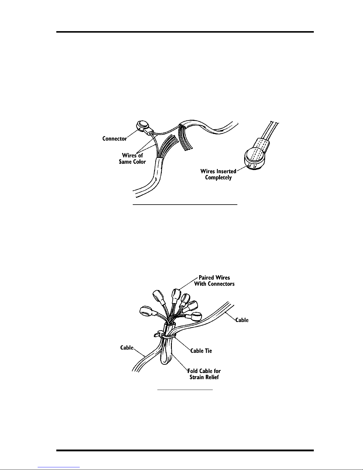
3. Take a wire from one of the cables and place it in one of the holes at the end of a splice
connector.
Make sure you push the wire all the way in. You can check this by looking
through the clear side of the splice connector.
4. Take the same colored wire from the other cable and place it in the other hole at the
end of the splice connector you used in step 2.
Make sure you push the wire all the way in. You can check this by looking
through the clear side of the splice connector.
C
ONNECTING
W
IRES
U
SING
S
PLICE
C
ONNECTOR
5. Use pliers to snap the yellow cap into place, securing the wires.
6. Repeat this procedure for each set of colored wires.
7. Use a cable tie to secure the two cables together as shown below.
Doing this provides a measure of strain relief which should prevent the
wires from pulling apart under normal conditions. Cut off the excess cable
tie when it is secure.
P
ROVIDING
S
TRAIN
R
ELIEF
Page 4
Product Numbers: 7957
Davis Instruments Part Number: 7395-010
Coupler Kit for Standard 4- and 6-Conductor Cables
Rev. C Manual (7/8/99)
This product complies with the essential protection requirements of the EC EMC
Directive 89/336/EC.
© Davis Instruments Corp. 1996. All rights reserved.
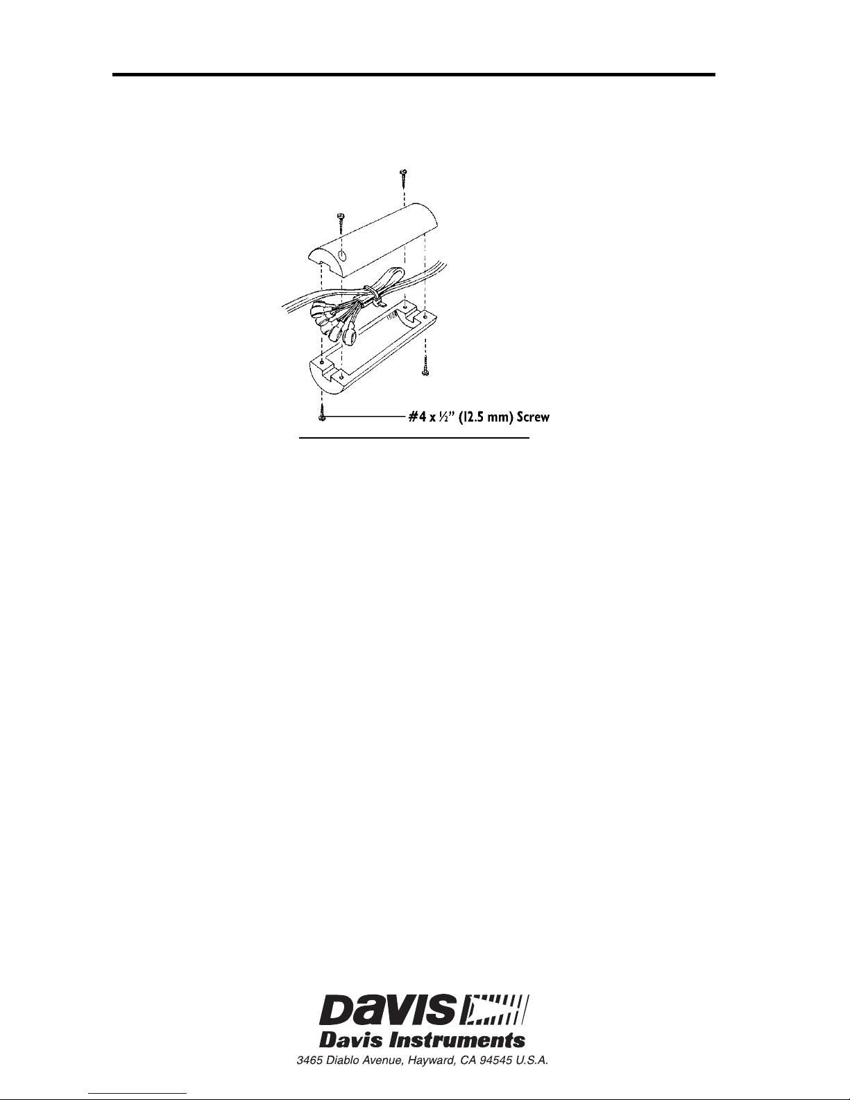
8. Gather the wires and splice connectors neatly together and enclose the in the two
halves of the protective shell as shown below.
Use the #4 x ∫ ” (12.5 mm) screws to join the two halves.
E
NCLOSE
C
ONNECTION
IN
P
ROTECTIVE
S
HELL
T
O
C
ONNECT
THE
C
ABLES
U
SING
THE
C
OUPLER
1. Place the cable plug at the end of one of the cables into one end of the coupler.
2. Place the cable plug at the end of the other cable into the other end of the coupler.
3. Enclose the connection in the two halves of the protective shell.
Use the #4 x ∫ ” (12.5 mm) screws to join the two halves.
 Loading...