

Page 1
®
Product # 8156GD, 8156HD, 8156VSS & 8156VF
Page 2

One Year Limited Warranty
We warrant our products to be free of defects in material and workmanship for one year from date of original purchase. We make every effort to carefully manufacture our products to the highest standards of quality. Occasionally, however, parts may be missing, defective, or damaged.
If you have a defective part, please call 1-510-732-7814 for authorization before returning the item for repair
or replacement. Upon receiving authorization, return the product to us, shipping charges prepaid. Include
proof of purchase and a written explanation of the problem. During the warranty period, we will, at our
option, either repair or replace the product free of charge.
This warranty does not cover damage due to improper installation or use, negligence, accident, unauthorized service, or the incidental or consequential damages beyond the Davis products themselves. Implied
warranties are limited in duration to the life of this limited warranty. Some states do not allow limitations on
how long an implied warranty lasts, or the exclusion or limitation of incidental and consequential damages,
so the above limitations may not apply to you. This warranty gives you specific legal rights. You may have
other rights, which vary from state to state.
FCC Part 15 Class B Registration Warning
This equipment has been tested and found to comply with the limits for a Class B digital device, pursuant to
Part 15 of the FCC Rules. These limits are designed to provide reasonable protection against harmful interference in a residential installation. This equipment generates, uses, and can radiate radio frequency
energy and, if not installed and used in accordance with the instructions, may cause harmful interference to
radio communications.
However, there is no guarantee that interference will not occur in a particular installation. If this equipment
does cause harmful interference to radio or television reception, which can be determined by turning the
equipment on and off, the user is encouraged to try to correct the interference by one or more of the following measures:
• Reorient or relocate the receiving antenna.
• Increase the separation between the equipment and receiver.
• Connect the equipment into an outlet on a circuit different from that to which the receiver is connected.
• Consult the dealer or an experienced radio/TV technician for help.
Changes or modifications not expressly approved in writing by Davis Instruments may void the user's
authority to operate this equipment.
Product Numbers: 8156GD, 8156HD, 8156VSS & 8156VF
Davis Instruments Part Number: 7395.192
DriveRight 600 User’s Guide
Rev. B Manual (March 26, 2003)
© Davis Instruments Corp. 2002-2003. All rights reserved.
This product complies with the essential protection requirements of the EC EMC Directive 89/336/
EC.
DriveRight is a registered trademark of Davis Instruments Corp. Windows is a trademark of Microsoft
Corporation.
Page 3

TABLE OF CONTENTS
INTRODUCTION TO THE DRIVERIGHT 600 .... ....... ...... ....... ...... ...........................1
A Note About the Concept of “Trips“ ...........................................................................1
A Word About Safe Use ..............................................................................................1
DriveRight Vehicle Management Software .................................................................2
USING THE DRIVERIGHT 600 .......................................... ...... ....... ...... ....... ...... . 3
Using the Four Buttons ...............................................................................................3
Changing Units of Measure ........................................................................................3
The Data Screens .......................................................................................................4
The Settings Screens .................................................................................................5
CALIBRATING THE DRIVERIGHT 600 ................................................................6
Calibrating from the Software (VSS & VF Only) .........................................................6
Calibration Using the Speedometer ............................................................................6
Calibration Using the Odometer .................................................................................8
DATA SCREENS ................................... .................................................... ..... 10
Current Readings Screen .........................................................................................10
Driver ID Code Entry & Digital Input Status Screen ..................................................11
Driver ID Code ..........................................................................................................12
Two Digital Inputs .....................................................................................................13
Activity Indicator ........................................................................................................13
Trip Start/End Log Screen ........................................................................................13
Trip Speed and Distance Log Screen .......................................................................14
Trip Acceleration/Deceleration Log Screen ..............................................................15
GPS Latitude and Longitude Position Screens .........................................................16
Odometer Screen .....................................................................................................17
Limits Screen ............................................................................................................17
SETTINGS SCREENS ...................................................................................... 18
Security Code Screen ...............................................................................................18
Clear Log Screen ......................................................................................................19
Alarm On/Off Screen ................................................................................................20
Calibration Screen ....................................................................................................21
Limit and Unit Settings Screen ................................................................ .................21
Time Entry ................................................................................................................22
Date Entry .................................................................................................................22
Year Entry .................................................................................................................23
i
Page 4

ISCELLANEOUS INFORMATION ................................................... ..................23
M
Accident Log .............................................................................................................23
Tamper Log ..............................................................................................................24
Battery Operation ......................................................................................................24
Battery Life ...............................................................................................................26
Display Lamp ............................................................................................................26
Restarting the DriveRight 600 ...................................................................................26
TROUBLESHOOTING GUIDE ...........................................................................27
Contacting Davis Technical Support .........................................................................29
TECHNICAL SPECIFICATIONS ......................................................................... 30
ii
Page 5

INTRODUCTION TO THE DRIVERIGHT 600
The DriveRight 600, in conjunction with the DriveRight Vehicle Management Software, provides advanced vehicle safety and use monitoring capabilities as well as comprehensive fleet management
capabilities. This manual explains how to use the DriveRight 600 display unit to view information.
NOTE: Altering the DriveRight 600’s limit s , dele tin g trip in fo rma tio n , and
calibrating the DriveRight 600 require entry of a security code
before changes may b e m ade.
A Note About the Concept of “Trips“
Much of the data stored and displayed by the DriveR ight 600 is sto red
and displayed by “trip.” For example, you may view the maximum
speed or the time spent drivin g over the set spee d limit durin g a single
trip. You may page back and forth thr ou gh all of the trips stor ed in the
DriveRight 600’s memory.
Stored in the DriveRight 600 is a “tr ip stop t ime” which r e pr esents the
amount of time for which the vehicle must be stopped before the DriveRight 600 ends the current tr ip. The default trip stop ti me is 5 minutes
(this setting may be alte red using the DriveRight Vehicle Management
Software). Whenever the v ehicle is n ot in motion for an amount of time
equal to the trip stop time, the DriveRight 600 saves the current trip
data to memory and begins a n ew tr ip (this new t rip will re main blan k
until the vehicle begins moving again).
NOTE: The DriveRight 600 also s aves the current trip data whenev er a
driver “logs out” (see “Driver ID Code Entry & Digital Input Status
Screen” on page 11).
A Word About Safe Use
It goes without saying that you should never attempt to change the
DriveRight 600 display while you are driving. Safe driving requires
extreme attentiveness. Changing the DriveRight 600 display while
driving may result in dangerous distraction. Only use the unit when
you are not operating your vehicle.
In addition, alwa ys wa rn drivers about the Driv eRight 600’s alarms. I f
an alarm sounds, a driver who has not been war ned may be startled or
get distracted trying to trace the source of the noise. In ei ther case, it
may create a safety concern, so warn drivers in advance.
1
Page 6

DriveRight Vehicle Management Software
The DriveRight Vehicle Management Software enables more
detailed tracking of vehicle u sa ge a nd access to some additional features of the DriveRight 600. The following is a list of the DriveRig ht
600 features which may o nly be accessed using the software.
❏
View information contained in the “accident log”
❏ View tamper information
❏ Enter or change the odometer reading or the odometer read-
ing’s unit of measure
❏ Set login alarm
❏ Set trip stop time
❏ Download up to 100 authorized driver ID codes.
❏ View trip type information
Although you may specify the type of trip using the DriveRight 600 display unit, you must have the softw are to
view trip type information.
❏
Configure GPS
Requires optional DriveRight 600 GPS module, #8157.
2
Page 7

USING THE DRIVERIGHT 600
This section briefly describes the use of the DriveRight 600 display
unit. The use of the four buttons (PLUS, MINUS, MODE, SET/
CLEAR) and the sequence of data screens and settings screens is
explained. Descriptions of the information and options available from
each screen are explained separately in “Data Screens” starting on
page 1 0 and “Settings Screens” starting on page 18.
Using the Four Buttons
The DriveRight 600 has four buttons: PLUS, MINUS, MODE, and
SET/CLEAR. The general use of each button is explained briefly
below:
❏
PLUS/MINUS
When a digit or segment (e.g., MPH or KPH) is flashing, use
the PLUS and MINUS keys to scroll forward or backward
(respectively) through the available options (usually 0 to 9).
When viewing any logged trip information screen, use the PLUS
and MINUS keys to page for w ard or backward (respectively)
through the stored trips.
❏
SET/CLEAR
When entering codes or setting limits, the flashing digit/segment indicates what will change if PLUS or MINUS is
pressed. Pressing and releasing SET/CLEAR causes the next
digit/segment to begin flashing.
From the Driver ID Code screen, press and hold SET/CLEAR (for
at least 2 seconds) to “log out.” The dri ver ID code is reset to 0000.
❏
MODE
Press and release MODE to move to the next data or information screen.
Press and hold MODE to switch between the group of data screens
and the group of settings screens.
When the unit is in sleep mode, p ress M ODE to “w ake” the u nit up .
Changing Units of Measure
To change units of measure, press and hold SET/CLEAR for at least 2
seconds while viewing the Current Readings screen. You may also
change units from the Limit and Units Settings screen by pressing
SET/CLEAR until either the km/h or MPH segment is flashing, and
then pressing PLUS to toggle between the two units of measure.
You may change the date display format from the Date Entry screen
and the time display format from the Time Entry screen.
3
Page 8
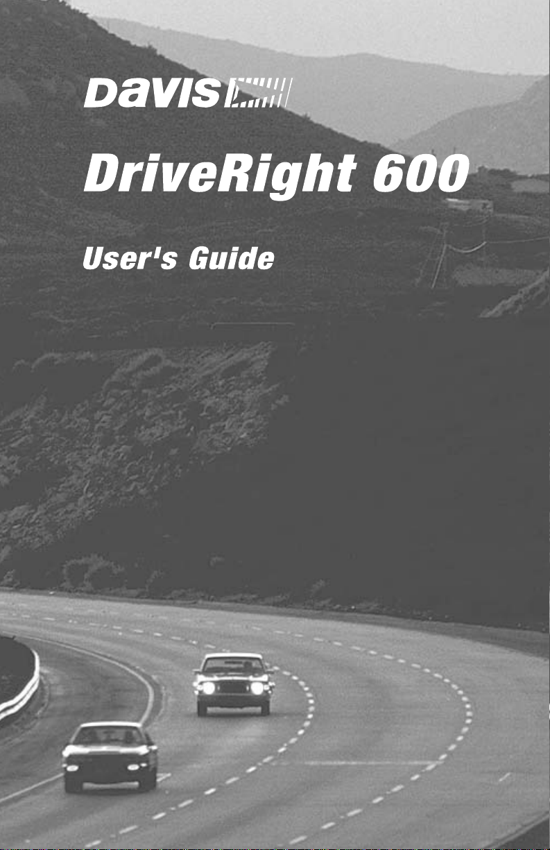
The Data Screens
The data screens enable you to view most of the information stored
by the DriveRight 600. To cycle through the data screens (in the
order shown below), press and release MODE.
NOTE: To view the settings screens, press and hold MODE unt i l the
NOTE: The GPS Latitude and Long itu de screens are not displayed i f
CURREN
T
SPEED
DISTANC
E
K
m
Current Readings
SP
EE
D
DECEL
G
Limits
Security Code Entry screen appears.
the DriveRight console i s not connected to a vehicle.
DAY.M
O
k
m/h
ACCE
L
G
Driver ID Entry
k
m/h
SETTINGS
ACCE
STAR
L
G
T
L
OG
E
ND
Trip Start/End Log
COD
E
P
M
TOTAL
P
M
DAY.M
O
Hr.
DISTANC
E
Odometer
GPS Latitude and Longitude
4
DAY.M
K
m
SPEED
L
OG
DISTANC
k
m/h
E
TIM
E
K
m
OVE
R
SPEED
O
Sec.
Trip Speed and Distance Log
DAY.M
O
L
OG
DECEL
COUNT
ACCE
L
COUNT
Trip Acceleration/Deceleration Log
DriveRight 600 Data Screens
Page 9
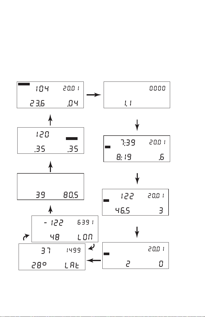
The Settings Screens
T o access the settings screens, press and hold MODE while viewing any
of the data screens. After a few seconds, the Security Code screen will
appear. To cycle through the settings screens (in the order shown below),
press and release MODE.
NOTE: T o view the data screens, press and hold MODE until the Current
Readings screen appears.
Year Entry
Date Entry
Time Entry
SPEED
DECEL
k
m/h
G
Limit and Units Settings
YEAR
SETTINGS
SETTINGS
SETTINGS
SETTINGS
ACCE
L
DAY.M
COD
E
SETTINGS
Security Code
O
SETTINGS
CLEAR LOG
Clear Log
A
M
ALAR
M
SETTINGS
Alarm On/Off
SPEED
G
k
m/h
SETTINGS
K
m
Calibration
DriveRight 600 Settings Screens
5
Page 10

CALIBRATING THE DRIVERIGHT 600
You must calibrate the unit before it will report the correct speed,
distance, decelera ti on, a nd a c celeration. Calibration adjusts the unit
to work properly with your vehicle’s VSS signal or with the vehicle’s differential and tire size.
Calibrating from the Software (VSS & VF Only)
If you have the DriveRight Fleet Management Software or DriveRight Vehicle Management Software and a VSS or VF DriveRight 600,
you may quickly and accurately calibrate the unit using the software, provided you kn ow the pulses per mile used by your vehicle’s
VSS (vehicle speed sensor).
❏
Contact your dealer’s service department for the pulses per
mile used by your vehicle’s VSS.
❏ Instructions on calibrating the DriveRight 600 using the soft-
ware can be found in the software he lp.
Calibration Using the Speedometer
In order to c ali br at e using the speedometer, you must drive steadily
at 40 km/h (25 MPH) and press a button on the DriveRight 600. The
DriveRight 600 bases its calibration on the speed of the v ehicle at the
moment of calibration which it assumes to be 40 km/h (25 MPH).
Because of the nature of this calibration procedure, we strongly recommend that it be performed by two people: one to drive the vehicle and one to operate the DriveRight 600.
NOTE: If you have entered a security code, you will need to enter that
code before the DriveRight 600 will allo w access to the calib ration screen.
1. Press and hold MODE to access the settings screens.
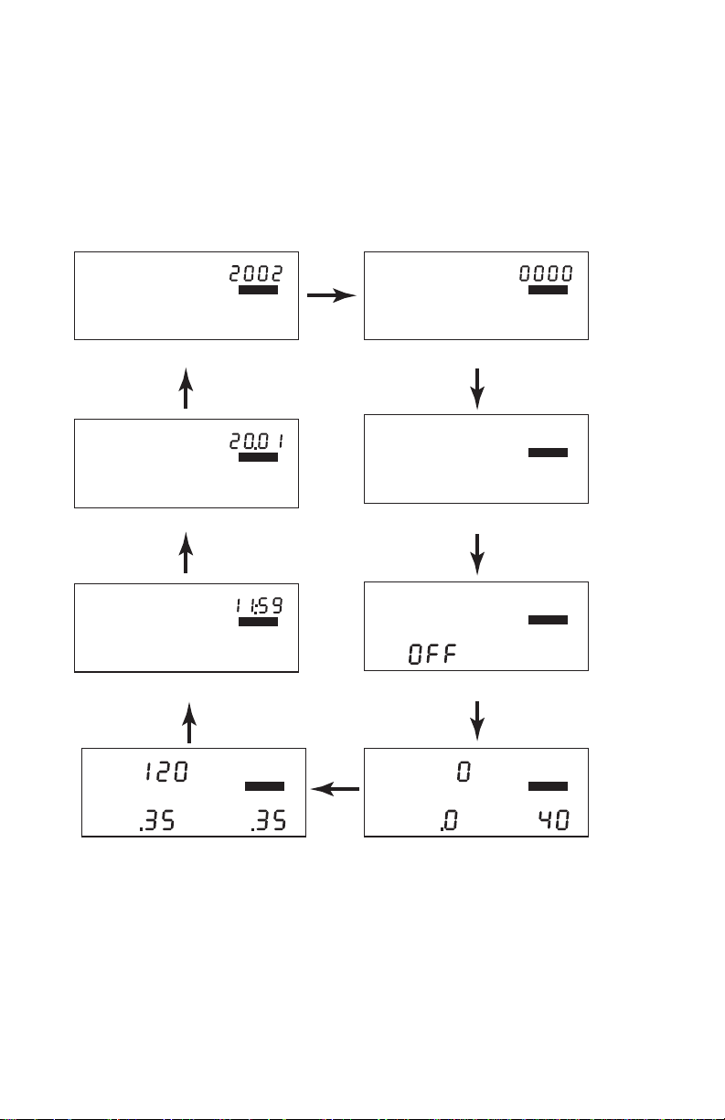
2. Press and release MODE until the Calibration screen appears.
The calibration speed (40 or 25 ) app ear s at the bo tto m righ t of the display. The uncalibrated speed reading appears at the top of the display,
along with the unit of measure (km/h or MPH). Note that until you
calibrate the DriveRight 600 this speed reading will be inaccu rate .
The distance, which appears in the lower left of the display, is not necessary for this calibration procedure
6
Page 11
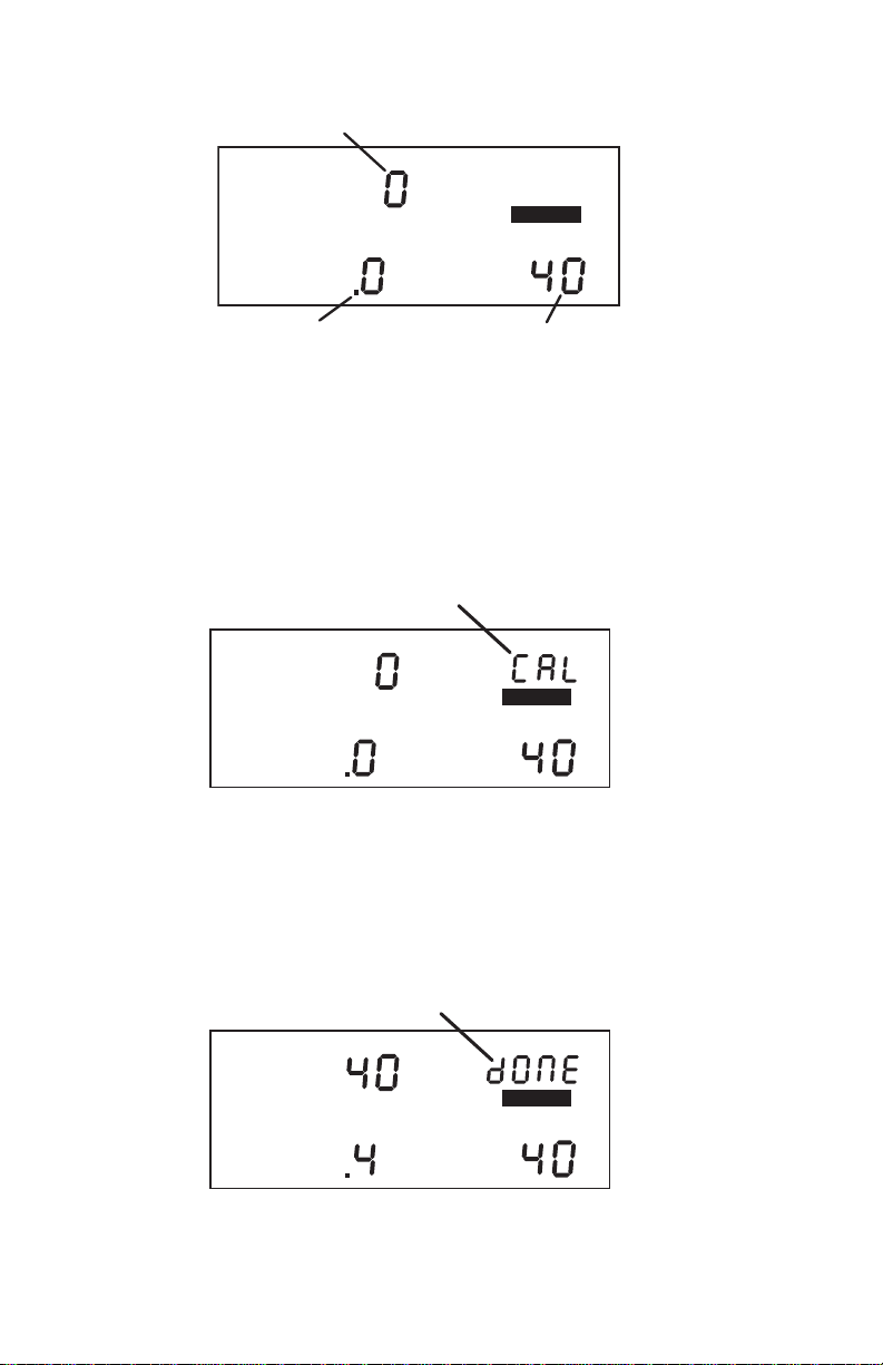
.
Speed Reading
MILES
K
m
MPH
k
m/h
SETTINGS
SPEED
D
ISTANCE
Distance Reading Calibration Speed
Calibration Screen
3. Drive the vehicle until you reach 40 km/h (25 MPH) and keep the
vehicle steady at that speed.
4. Once the vehicle is moving steadi ly at the calibration speed, press
and hold SET/CLEAR.
The word CAL appears in the top right of th e display when you press
SET/CLEAR. This indicates that the unit is in the process of calibrating.
Unit Calibrating
SPEED
D
ISTANCE
k
m/h
K
m
Unit Calibrating
SETTINGS
5. Continue to hold SET/CLEAR until the unit beeps and the word
“DONE” appears on the display.
This indicates that the unit has finished calibrati ng. The spe ed reading at
the top of the display will also change so that it reads much closer to
your speedometer’s reading.
Unit Finished Calibrating
SPEED
D
ISTANCE
Unit Finished Calibrating
k
m/h
SETTINGS
K
m
7
Page 12

6. Once the calibration is complete, drive the vehicle and compare
the vehicle’s speedometer to the DriveRight 600’s speed display.
Be aware that the DriveRight 600 responds t o changes in speed faster
than most vehicles’ speedometers. To accurately compare, you must
drive steadily at a speed for a short time.
7. If necessary, “fine tune” the calibration by pressing PLUS or
MINUS.
Each time you press PLUS or MINUS, the DriveRight 600 speed
reading adjusts up or down. Depending on the speed of the vehicle
and the calibration, you may or may not see a change in the speed
reading in the calibration screen each time you press the butto n.
NOTE: Pressing and holding PLUS or MINU S down
increases the rat e at which the DriveRig ht 600
adjusts the speed reading.
8. Continue to Press PLUS or MINUS until the DriveRight 600’s
speed reading agrees with your vehicle’s speedometer at a variety
of speeds.
9. When finished calibr ating, pr ess a nd hold MODE un til you retur n
to the data screen.
When you finish fine-tuning, press MODE to exit the calibration
screen. All information will be automatic al ly save d. Do not press and
hold SET/CLEAR in an effort to sav e the fi ne-tuned c alibration! If you
press and hold SET/CLEAR, the unit complete ly resets the calibra tion
number.
Calibration Using the Odometer
In order to calibrate using the odomet er, you must compare a distance reading tak en fr om your vehicle’s odometer to the Driv eRig ht
600 and adjust the DriveRight 600 to match the vehicle’s odometer.
Depending on how far you drive in order to calibrate the unit, this
can result in an extremely accurate calibration.
NOTE: We recommend that you driv e a m ini m um of 32km (20 miles)
when calib r ating the uni t .
Your vehicle’s speedometer and odometer may not be perfectly
linked. If they differ and you calibrate your DriveRight 600 using
the vehicle’s odometer, you may notice a discrepancy between the
DriveRight 600’s speed readings and the vehicle’s speedometer.
1. Obtain a rough calibration, using the speedometer as described in
“Calibration Using the Speedomete r” on page 6.
2. Reset your vehicle’s trip meter to zero or make a note of the
odometer reading.
8
Page 13

3. Make sure you have a new trip started on the DriveRight 600 (i.e.,
the distance travelled is 0.
To forcibly start a new trip, log out (see page 14 for details).
4. Drive the vehi cle for at least 32 km (2 0 miles).
The further you drive, the more accurate your calibration.
5. When you finish driving, compa re yo ur vehicle’s trip meter reading
to the distance travelled reading on the DriveRight 600.
At this point, what you will need to do is increase or decrease the distance measured by the DriveR ight 600 until it ag rees with y our veh icle’s
odometer reading. This is accomplished from the calibration screen.
6. Press and hold MODE to access the settings screens.
7. Press and release MODE until the Calibration screen appears.
The distance travelled appears at the lower left of the display. Note that
until you calibrate the Driv eRigh t 600, this distance readi ng will b e in accurate. The speed reading and cali bration speed, which appear on the
display as well, are not necessary for this calibration procedure.
Speed Reading
SPEED
D
ISTANCE
Distance Reading Calibration Speed
MPH
k
m/h
MILES
K
m
Calibration Screen
SETTINGS
8. Press PLUS or MINUS until the distance reading matches the trip
meter on your vehicle.
Depending on how many miles you drove, you may need to press PLUS
or MINUS several times before the distance reading changes.
NOTE: Pressing and holding PLUS/M INUS down increases the rate at
which the DriveRight 600 adjusts the distance reading.
9. When finished calibrating, press and hold MODE until you return
to the data screen.
Press MODE to exit the calibration screen. All information will be automatically saved. Do not press and hold SET/CLEAR in an effort to save
the fine-tuned calibration! If you press and hold SET/CLEAR, the unit
completely resets the calibration number.
9
Page 14

DATA SCREENS
The following section explains a ll the informa tion an d options av ailable in the various data screens. In addition to the options listed in
the individual sections below, in every screen you have the following two options:
❏
Move to the next Data Screen
Press and release MODE.
View the Settings Screens
❏
Press and hold MODE.
Current Readings Screen
The current r eadings scr een displays cons tantly updatin g (as long as
the car is moving) speed, distance (for the current trip), and acceleration/deceleration readings (acceleration is positive, deceleration is
negative). The current date (or time) is a lso dis played on t his screen.
Current Speed
CURREN
T
SPEED
DISTANC
E
Distance Travelled
on Current Trip
Current Readings Screen
k
m/h
K
m
Date (or Time)
DAY.M
ACCE
L
G
Current Acceleration
(or Deceleration)
O
You have the following options from the Current Readings Screen:
Toggle Between Date and Time Display
❏
You may display either the date or the time. To toggle
between the two, press and release SET/CLEAR.
❏ Change Units of Measure
To change the units of measure in which data is displayed
from metric to U.S. units (or vice versa), press and hold
SET/CLEAR for approximately 2 seconds. This does not
change the date o r time display format.
❏
Specify Trip Type
There are four types of trips stored by the DriveRight 600:
Business, Personal, Commute, and Other. The trip type is
stored along with the rest of the trip information and is
automatically saved when information is downloaded
using the software.
10
Page 15

NOTE: Although you may specify the type of trip using the
DriveRight 600 display unit, you must have the software to view tr ip type information.
T o cha nge the typ e of trip, press and ho ld MINUS. The trip type
screen will appear--do not release MINUS.
MILES
Trip Type Screen
As long as you hold MINUS, the Drive Right 600 will cy cle through
the letters representing t he v ariou s tri p t yp es: b = Business, P = Personal, C = Commute, O = Other. Release MINUS when the desired
trip type appears.
NOTE: You may change the trip type anytime during a trip.
Trip type information is saved when the trip ends.
❏ Turn Display Lamp On/Off
To turn the DriveRight 600’s display lamp on or off, press
PLUS. Y ou must be viewin g the Current Reading s Screen, the
Trip Start/End Log screen, the Trip Speed and Distance Log
screen or the Trip Accel/Decel Log screen to turn the display
lamp on and off.
Driver ID Code Entry & Digital Input Status Screen
The Driver ID Code Entry Screen enables you to enter the driver ID
code, displays the status of the two digital inputs, and also includes an
activity indicator for the reed switch (GD and HD models) or VSS
input (VSS and VF models).
COD
E
Driver ID Code Entry Screen
11
Page 16

Driver ID Code
When using the DriveRight 600 to monitor the driving of multiple
drivers, assign each driver a unique 4-digit ID code. Before driving
the vehicle, the driver must ent er his or her ID code. Th e DriveRight
600 stores the driver ID code with the rest of the trip information,
which enables you to view information for each individual driver.
In addition, data downloaded by the software is segregated by
driver ID code, enabling detailed tracking of multiple drivers.
The DriveRight Vehicle Management Software allows you to use the
driver ID code to track locations instead when a single driver is
using a vehicle. You may also use the software to turn on an alarm
which will alert the driver when a driver ID (or location ID) has not
been entered.
NOTE: Driver ID code 0000 (four zeros) is used to view information for
the vehicle (all drivers) an d should not be assigned to any
driver, unless only a single driver uses the vehi c le .
In addition to marking data as belonging to a particular driver, the
driver ID code may be used when viewing information on the display to filter the information being viewed. To view information for
one specific driver, enter that driver’s ID code in this screen. The
DriveRight 600 display will filter out any data not assigned that
code.
12
To view all information, regardless of driver ID code, enter the
reserved code: 0000.
You have the following options from the Driver ID Code Entry
Screen:
❏
Enter a Driver ID Code
The flashing digit in the code is the active digit. Press and
release PLUS or MINUS to cycle forward or backward
through the available entries for the active digit (0 to 9). To
change the digit which is active, press and release SET/
CLEAR. Each time you press SET/CLEAR, the next digit
become active.
If you have lo a de d driver ID codes into the DriveR ig ht 60 0, then
only those codes will be accepted. A “no” will apear on the
screen if a wrong ID code is entered. A code of “0” will still be
accepted.
Page 17

❏ Log Out
To “log out” press and hold SET/CLEA R for 2 seconds, until
the code resets to 0000. As soon as a driver logs out, the current trip is ended and data for that trip stored in the DriveRight 600’s memory. Note that you may not log out when the
vehicle is in motion.
Two Digital Inputs
Two digital inputs allow you to track the operation of lights or other
electrically powered accessories on the vehicle. A typical application
would be to monitor the headlights and the brakes. The screen displays “1” if the input is on, and “0” if th e inpu t is off. The status of the
inputs is stored in the trip log.
Activity Indicator
Primarily useful for troubleshooting the installation, the small “dot”
between the two activity indicators will appear whenever the reed
switch used with the 8156GD and 8156HD models is closed, or wh enever the VSS input used with t he 815 6 VSS a nd 8156VF models is high.
The reed switch closes once each time the vehicles drive shaft rotates.
Trip Start/End Log Screen
The Trip Start/End Log Screen shows the start and end time for each
trip currently stored in the DriveRight 600’s memory. To view tri p
times for a specific driver, enter that driver’s ID code in the Driver ID
Code Entry screen. To view all trip times for the ve hic le, e nt er I D c ode
0000.
NOTE: If the end time for a trip is “dash ed ,” it m ean s t hat you are view-
ing the current trip, which has not yet ended (unless the unit was
restarted in the middle of a trip).
Trip Start Time Date
DAY.M
P
M
STAR
T
L
OG
TOTAL
E
ND
Trip End Time Trip Duration
Trip Start/End Log Screen
P
M
O
Hr.
13
Page 18

You have the following option from the Trip Start/End Log Screen:
Page Through Stored Trip Information
❏
Press MINUS to page backward through stored trip information. Press PLUS to page forward through stored trip
information. Hold the button down to increase the speed at
which the DriveRight 600 pages. When you reach the first
or last stored trip, the DriveRight 600 will no longer page
in that direction.
Trip Speed and Distance Log Screen
The Trip Speed and Distance Log Screen shows the maximum
speed, distance trave lled, and amount of t ime spent driving ov er the
set speed limit for each trip currently stored in the DriveRight 600’s
memory.
To view trip speed and distance information for a specific driver,
enter that driver’s ID code in the Driver ID Code Entry screen. To
view all trip speed and d istance infor mation for t he vehicle, e nter ID
code 0000.
Maximum Speed During Trip Date
SPEED
L
OG
DISTANC
MAXIMUM
E
k
m/h
K
m
TIM
OVE
SPEED
DAY.M
O
E
R
Sec.
14
Distance Travelled
During Trip
Trip Speed and Distance Log Screen
Amount of Time Spent Driving Over
Set Speed Limit During Trip
You have the following option from the Trip Speed and Distance Log
Screen:
❏ Page Through Stored Trip Information
Press MINUS to page backward through stored trip information. Press PLUS to page forward through stored trip
information. Hold the button down to increase the speed at
which the DriveRight 600 pages. When you reach the first
or last stored trip, the DriveRight 600 will no longer page
in that direction.
Page 19

Trip Acceleration/Deceleration Log Screen
The Trip Acceleration/Deceleration Log Screen shows the number of
times the set acceleration and deceleration limits were exceeded during each trip currently stored in the DriveRight 600’s memory. (Each
time the limit is exceeded, 1 “count” is recorded, regardless of the
amount of time for which the limit was exceeded.)
To view trip a cceleration/deceleration information for a specific
driver, enter that driver’s ID code in the Driver ID Code Entry screen.
To view all trip acceleration/deceleration information for the vehic le ,
enter ID code 0000.
L
OG
COUNT
DECEL
ACCE
Date
L
DAY.M
COUNT
O
Number of Times
Deceleration Limit
Exceeded During Trip
Trip Acceleration/Deceleration Log Screen
Number of Times
Acceleration Limit
Exceeded During Trip
You have the following options from the Trip Acceleration/Deceleration
Log Screen:
❏ Page Through Stored Trip Information
Press MINUS to page backward through stored trip information. Press PLUS to page forward through stored trip information. Hold the but ton dow n to increase the speed at wh ich
the DriveRight 600 pages. When you reach the first or last
stored trip, the DriveRight 600 will no longer page in that
direction.
15
Page 20

GPS Latitude and Longitude Position Screens
The GPS Position Screens alternate between La titude and Lon gitude
to show your current position, speed, and di recti on.
NOTE: The GPS screens are not displayed if the DriveRight is not
connected to a vehicle .
NOTE: The GPS may take up to s everal mi n utes to start tracking a
new trip, depending on the overhead obstructions surrounding
the vehicle.
Whole Degrees Latitude Decimal Degrees Latitude
Current Direction GPS Latitude Position Screen
Latitude Screen
16
Whole Degrees
Current Speed Longitude
Longitude Screen
Decimal Degrees
A “NO” on the Latitude and Longitude screens indicates the GPS
module is not able to track your current posit ion . The last known
position will be displayed.
N
O
Not Tracking
Not Tracking Indicator
Page 21

Odometer Screen
The Odometer screen displays the vehicle’s odometer reading which
must be set from the DriveRight Vehicle Management Software. The
odometer reading is s pr ead ac r oss the t wo di git r egi sters at the bo ttom
of the screen and may take some getting used to (the odometer reading in the screen shown below is 5,812.2 km).
NOTE: The odometer readings is ALWA YS shown in the unit of measure
Limits Screen
The Limits screen enables you to view the set speed, acceleration, and
deceleration limits for this DriveRight 600 unit. You may not change
any of the limits fr om this scre en; limits ma y only be c hanged f r om th e
Limits and Units Setting screen (see “Time Entry” on page 22), or
using the DriveRight Vehicle Managem ent Softwa re.
DISTANC
E
K
m
Odometer Reading (5,812.2 km)
Odometer Screen
in which it was entered. T o change the unit of measure, you need
to reenter the odometer re adi ng using the software.
Acceleration and deceleration is measured in “G’s” (the gravitational
constant which repr esen ts the acceler ation of a n object wh en fa lli ng t o
earth in a vacuum). 1G is roughly equal to an acceler ation of 35 km/h
(22 MPH) per second.
Speed Limit
SP
EE
D
DECEL
Deceleration Limit Acceleration Limit
Limit Sett ings Screen
k
m/h
SETTINGS
ACCE
L
G
G
17
Page 22

SETTINGS SCREENS
The following section explains a ll the informa tion an d options av ailable in the various settings screens. In addition to the options listed
in the individual sections below, in every screen you have the following two options:
❏
Move to the next Settings Screen
Press and release MODE.
View the Data Screens
❏
Press and hold MODE.
Security Code Screen
If you are concerned about unauthorized changing of DriveRight
600 settings, you may enter a security code from the DriveRight or
the software. After you have entered a security code, the DriveRight
600 will not allow access to the rest of the settings screens until the
correct 4-digit se curity code is enter ed. T he unit allow s five attem pts
to enter the correc t security code be fore returning to the Current
Readings screen and activating the tamper indicator (pressing
MODE to move to the next settings screen is considered an
“attempt”). The time and date of the unsuccessful tamper attempt is
stored and may be viewed using the DriveRight Vehicle Management Software.
NOTE: Use security code 0000 (four zeros) if you do not want to pass-
word-pro t ect calibration, since the unit defa ults to that code
when first displaying the Security Code screen.
18
COD
E
SETTINGS
Security Code Screen
You have the following options from the Security Code Screen:
Enter the Security Code
❏
The flashing digit in the code is the active digit. Press and
release PLUS or MINUS to cycle forward or backward
through the available entries for the active digit (0 to 9). To
change the active digit, press and release SET/CLEAR.
Each time you press SET/CLEAR, the next digit bec omes
active. Once the correct security code has been entered,
press MODE to move to the next settings screen.
Page 23

NOTE: If the entered code is correct, the clear all log data
❏ Set or Change the Security Code
Use PLUS and MINUS to enter your current code (if you are
entering a secur ity code for the fir st time, make sure 0000 is
entered). Press and hold SET/CLEAR until the word CHG
(change) appears on the display.
Use PLUS and MINUS to enter the desired secu rity code. When
finished, press MODE to save the new code and move to the Clear
Log Screen.
Clear Log Screen
screen appears when you press MODE . If th e entered
code is not correct, the word NO appears on the di splay. You may attempt to enter the correct code five
times before the unit returns you to the Current Readings screen and activates the tamper indicator, if the
tamper indicator is enabled.
COD
E
SETTINGS
Change Secur i ty Code
The clear all log data sc reen allows you to per form a “ to tal c lea r” func tion which erases all data for every trip in your log at once.
CLEAR LOG
Clear Log Screen
SETTINGS
NOTE: Accident and tamper log data cannot be cleared.
19
Page 24

You have the following option from the Clear Log Screen:
Clear all Log Data
❏
Press and hold SET/CLEAR. The word CLR (clear)
appears in the display t o in dic a te th at t he unit is preparing
to clear all log data. To protect against accidental clearing
of data, you must press and hold SET/CLEAR for 3 seconds before the unit clears data.
Continue to hold SET/CLEAR until the unit beeps and the word
CLR disappears from the display. This indicates that the u nit is in
the process of clearing data. The unit b eeps and the word dONE
appears in the display when the unit finishes clearing data.
Alarm On/Off Screen
The Alarm On/Off screen enables you to toggle the DriveRight
600’s audible alarm on and off. When the alarm is on, the unit will
beep when any of the set limits is exceeded, as a warning to the
driver. Turning the alarm off will disable the beeping, though the
DriveRight 600 will continue to record violations of the set limits.
CLEAR LOG
Preparing to Clear Log Data
CLEAR LOG
Unit Finished Clearing Data
SETTINGS
SETTINGS
20
ALAR
M
Alarm On/Off Screen
SETTINGS
Page 25

You have the following option from the Alarm On/Off Screen:
Toggle the Alarm Setting
❏
To toggle the alarm setting from On to Off (or vice versa),
press and release SET/CLEAR. Each time you press SET/
CLEAR, the display changes to read ON or OFF, depending
on the alarm’s statu s.
Calibration Screen
The Calibration screen enables you to calibrate the DriveRight 600 for
your vehicle. See “Calibrating the DriveRight 600” on page 6 for
details.
Limit and Unit Settings Screen
The Limit and Unit Settings screen allows you to set limits for speed,
acceleration, and deceleration. You may also change the unit of measure in which speed and distance information is displayed (km/h or
MPH).
Speed Limit
SP
EE
D
DECEL
k
m/h
SETTINGS
ACCE
L
G
Deceleration Limit Acceleration Limit
Limit Entry Scr een
G
You have the following options from the Limit and Unit Se tt ing s Sc re en:
Enter/Change a Limit
❏
Use SET/CLEAR to change the active digit and use PLUS
and MINUS to enter the desired limit for speed, acceleration,
and deceleration.
NOTE: The maximum limit settings are as follows: Speed 255,
Accelerat i on and Decelerat ion 2.55.
❏ Change the Unit of Measure
Press and release SET/CLEAR until the display segment
(km/h or MPH) is flashing. Use PLUS and MINUS to toggle
between km/h and MPH. Whatever segment is displayed
when you press MODE to exit this screen is the unit of measure in which speed and distance information will be displayed.
21
Page 26

Time Entry
The Time Entry screen allows you to set the time and to select the
format (12 hour or 24 hour) in which you want time displayed.
❏
❏
A
M
SETTINGS
Time Entry Screen
You have the following options from the Time Entry Screen:
Set the Time
Use PLUS and MINUS to set the time. If you are displaying
time in the 12 hour format, remember to choose either AM
or PM. To do this, follow the same procedure as if you wer e
changing the format of the time display, as explained
below.
Change the Time Display Format
Press and release SET/CLEAR until the PM, AM, or 24HR
segment is flashing. Press PLUS to cycle through the three
possible options: PM, AM, and 24HR. When the desired
option appears in the display, stop. The segment displayed
when you press MODE to exit this screen sets the format in
which time will be displayed.
Date Entry
The Date Entry screen allows you to set the date and to select the
format (Day.Month or Month:Day) in which you want the date displayed.
22
NOTE: The unit will not automatically conve rt the time fr om
12 hour to 24 hour or vic e versa. You must enter the
time in the new format yourself.
DAY.M
O
SETTINGS
Date Entry Screen
Page 27

❏
❏
Year Entry
The Year Entry screen allows you to enter the correct year, which will
allow the unit to automatically adjust for leap years.
❏
You have the following options from the Date Entry Screen:
Set the Date
Use PLUS and MINUS to set the date.
Change the Time Display Format
Press and release SET/CLEAR until the Mo:Day or Day.Mo
segment is flashing. Press PLUS to toggle between the two
segments. When the desired format appears in the display,
stop. The segment displayed when you press MODE to exit
this screen sets the format in which the date will be displayed.
YEAR
SETTINGS
Year Entry Screen
You have the following option from the Year Entry Screen:
Set the Year
Use PLUS and MINUS to se t the Year.
MISCELLANEOUS INFORMATION
Accident Log
The DriveRight 600 has room in me mory for 10 “accident” logs which
show the vehicle‘s speed for the 20 seconds before and after a sudden
deceleration. Information is written to the “accident” log any time the
vehicle exceeds the unit’s set deceleration limit. Also, the last 20 seconds of trip information for eac h of the last 20 trips is saved i n the ac cident log.
The information in the accident log may be downloaded, viewed,
printed, and stored using the DriveRight Fleet Management Software
or the DriveRight Vehicle Management Software.
23
Page 28

Tamper Log
The following actions will be logged as a tamper attempt:
❏
❏ Five incorrect entries in a row for the Security Code
❏ DriveRight is plugged back into the car (Tamper is logged but
❏ DriveRight is rebooted
When a tamper is logged, the word “T AMPER” appears on all screens
if the tamper light has been enab led using the softwar e. P lus, the time
at which the tamper attempt occurred and the cause of the tamper is
stored in the tamper log. The last 10 tamper events can be downloaded, viewed and printed, using the DriveRight Vehicle Management Software.
To clear the flashing TAMPER segment, enter the correct security
code (see “Security Code Screen” on page 18). The tamper indicator
is also cleared after data is downloaded.
The DriveRight 600 is unplugged (loses power)
not displayed on the console)
ACCE
DAY.M
L
CURREN
SPEED
DISTANC
TAMPE
R
T
k
m/h
E
K
m
Tamper Indicator Flashing
Tamper Indicator (Current Readings Screen)
O
G
NOTE: All data in the DriveRight 600 is stor ed in “n on-volatile” mem-
Battery Operation
The DriveRight 600 is designed to be taken out of your vehicle so
the data may be reviewed anywher e. If you disconn ect the unit from
its power source (the vehicle) it will automatically swi t ch to battery
power. The word BAT appear in the lower left corner of all screens
to indicate that you are running on battery power.
BA
24
ory which means no data will be los t e ven if p ower is removed.
DAY.M
CURREN
SPEED
DISTANC
T
T
E
Battery Indicator
MPH
k
m/h
ACCE
K
m
O
L
G
Battery Power Indicator
Page 29

NOTE: If you notice that the LCD is fa di ng when running on battery
power, it means your battery power is low. You should replace
your battery as soon as possible.
To install a new battery, insert the battery as shown below.
Installing the Battery
When operating under battery power, the unit will undergo a few
changes in operation in order to conserve battery power:
If you go more than 5 minutes without pressing a button, the
❏
unit enters “sleep mode.”
In sleep mode, all but the most essential unit functi ons (th at
is, time and date) shu t down. The display goes blank and no
data is recorded when the unit is “asleep.”
NOTE: The unit never goes into sleep mode when connected to
your vehicle (i.e., receiving power from your vehicle’s
battery).
To “wake up” the unit, press MODE or reconnect the unit to your
vehicle so it receives power from your vehicle’s battery.
❏
The display lamp is disabled.
You cannot turn on the unit’s display lamp.
The GPS Latitude and Longi tude position screen is not dis -
❏
played.
The Latitude and Longitude scr een will not appear when you
scroll through the DriveRight 600 data screens.
25
Page 30

Battery Life
When removed from a vehicle, th e Drive Ri ght unit ta ps into its
own battery for power (instead of relying on the vehicle’s battery).
On the unit’s battery alone, a unit will operate for 260 hours or, in
sleep mode for 4 months.
The life of the unit’s battery depends on your download schedule.
For example, if you take the unit out of the vehicle 5 days a week,
8 hours a day, the unit’s battery can last up to 16 months. In that
situation, because not a ll ou t- of-vehic le t ime w ill be spen t in sleep
mode and because of the occasional delay in returning the unit to
the vehicle, we recommend replacing the battery every year. If at
any time the LCD display begins dimming, the battery is low and
due for replacement.
If you plan to store a unit out-of-vehicle for more than a week, we
recommend removing the battery. When you replace the battery,
data and settings are not lost but you will need to reset the date
and time.
Display Lamp
To read the DriveRight 600 at night, use the display lamp. To toggle
the display lamp on and off, press PLUS when viewing the Current
Readings screen. Be aware that the display lamp does not work
when the unit is operating on battery power.
NOTE: The display lamp automatically shuts itself off after 10 minutes
if the vehicle is stopped.
Restarting the DriveRight 600
If DriveRight 600 display “locks up,” you may res tart the DriveRight 600 by pressing and releasing MODE and P LUS at the same
time. No log data, settings, or code information is lost when you
restart the uni t.
NOTE: The tamper indicator will appear if you restart the unit in this
way, if the tamper indicator light is set.
If the DriveRight 600 is still locked up, you must remove and reinsert the battery and reset the time.
26
Page 31

TROUBLESHOOTING GUIDE
While the DriveRight 600 is designed to provide years of trouble-free
operation, occasional problems may arise. If you ar e having a pr oblem
with your unit, please chec k t he follo win g gu id e before calling the factory. You will be able to solve many of the problems yourself. If, after
checking this guide, you are still unable to solve the problem, please
call the factory at 1-510-732-7814 for further instructions. Y ou may also
check the support section of our website (www.davisnet.com) or send
e-mail to tech support (support@davisnet.com).
Please do not return your unit for repair without prior authorization.
Many of the troubleshooting suggestions below relate to the position-
ing of the ma gnet and se nsor in driveshaft mounted DriveRight 600
units. If you have a VSS version, you should ignore these suggestions.
NOTE: We will be glad to answer any questions you may have regarding
the operation of the DriveR ight console. We cannot, howev er,
answer any questions relating to the installation of the unit in
your vehicle.
❏ I can’t turn my lamps off.
Make sure you are in the current readings screen when you
hit +.
When operating on batter power, the LCD segments are faint.
❏
Battery power is low. Replace the battery (see “Battery Operation” on page 24).
❏ The BAT segment is on when the unit is plugged into the car.
The unit is not getting primar y pow e r (from the vehicle’s battery). Check the fuse in the power line for your car.
❏
My buzzer is faint or not audible when the unit is operating on
battery power.
This is normal.
❏
My DriveRight 600 and my speedometer do not agree.
From the calibration screen, use the PLUS and MINUS keys
to fine-tune the calibration.
NOTE: The DriveRight 600 responds to changes in speed
faster than most speedometers.
❏ My speed is intermittently reading zero while driving.
This could be one of two things. First, make sure the speed
sensor is within 10-16 mm (3/8"- 5/8" ) of the magnet. If it is ,
make sure the installed speed sensor protrudes at least 20
mm (3/4") from th e bra ck e t.
27
Page 32

❏ My speed reads zero while driving.
There could be a number of things wrong. Make sure the
DriveRight 600 is plugged in. Make sure the DriveRight
600 is calibrated. Make sure the speed sensor is within 1016 mm (3/8"- 5/8") of the magnet. Make sure the unit is not
running on batt ery power (see “Battery Operation” on
page 24). If it is check the fuse in the power line. If all of
this fails to solve the problem, consult the trouble shooting
section of your Installation Guide.
❏
The speed reading on the DriveRight 600 agrees with my vehicle’s speedometer, bu t the distance reading on the DriveRight
600 and my odometer differ (or vice versa).
For best accuracy, you should calibrate using the car’s
odometer (see “Calibration Using the Odometer” on
page 8). You may readjust the unit’s calibration periodically (to maintain accuracy) use the PLUS and MINUS buttons to readjust the distance reading to match the vehicle’s
trip meter reading after a long trip.
❏
The DriveRight 600 seems to be recording erroneous readings at low speeds.
Excessive mechanical vibrations at low speeds can cause
erroneous readings. Have your installation chec ked if you
have this problem.
❏
The DriveRight 600 indicates erroneous decelerations at low
speeds (VSS models only).
On some cars, the wrong dip switch settings can ca use the
DriveRight 600’s speed reading to abrutly drop to zero at
around 10 to 13 mph, which generates an erroneous deceleration log. Check your VSS cable dip switch settings if
you have this problem.
❏
The display is black or all the segments appear to be on.
The display was left in direct sunlight. The display will
return when it cools down. Even though the display is
black, the DriveRight 600 continues to r ecord data.
❏
The tamper light won’t go off.
Enter your security code (see “Tamper Log” on page 24).
I’ve forgotten my secret code.
❏
If you have the software, you can read the vehicle’s code.
Otherwise, ship the unit back to us with a check for $25.00
and a note explaining th e sit u at ion . We will return the uni t
to you with the cod e set to 0000.
28
Page 33

Contacting Davis Technical Support
If you have questions, or encounter problems installing or operating
your DriveRight 600, please contact Davis Technical Support. Most
questions can be answered while you’re on the phone. Sorry, we are
unable to accept collect calls.
NOTE: Please do not return items to the factory for repair without prior
authorization.
❏ (510) 732-7814 – Monday through Friday, 7:00 a.m. to 5:30 p.m.
Pacific Time.
❏ (510) 670-0589 – Fax to Technical Support.
❏ support@davisnet.com – E-mail to Technical Support.
❏ info@davisnet.com – E-mail to Davis Instruments.
❏ www.davisnet.com – Product documentation is available on the
DriveRight Support section of our website. Watch for FAQs and
other updates.
29
Page 34

TECHNICAL SPECIFICATIONS
Displays current speed in MPH or km/h.
Speed
Acceleration
and
Deceleration
Alarms
Distance
Time & Date
Accident Logs
(AL)
Security
Records maximum speed for each trip
Records total time in which speed exceeded set limit for each trip
Accuracy ±1%
Displays current acceleration in g’s (an acceleration of 22 MPH/sec. or 35 km/h/sec.).
Records number of times acceleration exceeded specified limit for each trip.
Records number of times deceleration exceeded specified limit for each trip.
Accuracy: ±5%
Audible alarm (optional) for exceeding speed, acceleration, and deceleration limits
Visible alarm message for exceeding speed, acceleration, and deceleration limits
Driver ID/Location ID code entry reminder alarm (requires software to set)
Displays and records total distance travelled duri ng cur rent trip in miles or kilometers.
Records overall distance (odometer requires software to set).
Specifies miles as business, personal, commute, or other.
Accuracy: ±1%
Displays current date in Month:Day or Day:Month format.
Displays current time in 12- or 24-hour format.
Records start and end time for each trip.
Records total time for each trip.
Accuracy: ±2 seconds/day
Records vehicle speed in last 20 seconds before and after deceleration limit exceeded.
Stores 10 separate accident logs.
Stores last 20 seconds of each of the last 20 trips.
Owner-specified 4-digit password protects settings and data.
Tamper indicator message appears if unit is disconnected.
Tamper indicator appears if incorrect security password is entered 5 times.
Tamper log stores time and date of last 10 tamper alerts.
Time and date of each connect and disconnect is recorded.
Sensor Type
Lamp
Primary Power
Secondary Power
Digital Inputs
Fuses (Power &
Digital Input)
Temperature
30
VSS input or rugged reed switch sensor with magnet for mounting on vehicle driveshaft
(rear wheel drive) or CV joint (front wheel drive).
Illuminated display
11 to 18 VDC (12 VDC nominal)
3-volt CR123 lithium battery (included) allows display unit to be removed from car.
Battery operating time is approximately 260 hours when it is disconnected from vehicle.
Battery life is up to four months in sleep mode.
2 digital inputs. Input 1 : green wire; Input 2: yellow wire
Input Impedance: >1 Megaohm
High input range: 3 VDC min, system voltage max
Low input range: -0.5 min to 1.0 VDC max
Input 1 Sampling: Start and stop of trip, GPS record, Accident Log
Input 2 Sampling: Start and stop of trip, GPS record
Input power requirements: 12 VDC nominal
Fuses (3): 3AG, .25A, Slo-Blo (1.25 x .25”, 6.4 x 31.8mm)
3AG (1 1/4” x 1/4”, 6.4mm x 31.8mm), .25A, Slo-Blo
Operating range -4° F to 185° F (-20°C to 85°C)
Page 35

TECHNICAL SPECIFICATIONS
Size
Display
Mounting
Options
5.25” x 2.25” x 0.86” (132 mm x 57 mm x 22 mm)
LCD display size: 3.20” x 1.30” (81 mm x 33 mm)
Visor clip for mounting on visor or door pockets.
Double-sided tape for mounting on dashboard and other surfaces.
Velcro with pressure-sensitive adhesive for mount ing on dashboard and other surfaces.
Mounting bracket with right angle adapter for special mounting needs.
31
Page 36

3465 Diablo Avenue, Hayward, CA 94545-2778 U.S.A.
510-732-9229 • Fax: 510-732-9188
E-mail: info@davisnet.com • www.davisnet.com
 Loading...