

Page 1
C
ONSOLELINK
I
NSTALLATION MANUAL
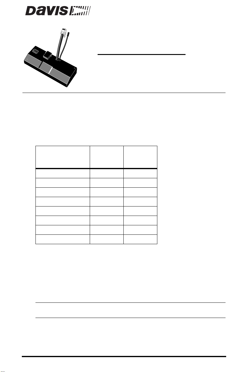
The ConsoleLink transmits weather data from your host weather station to
other DavisTalk™ compatible consoles and receivers. This allows you to send
weather data to one or more locations without using any wires.
The ConsoleLink connects to the Weather Monitor II and Weather Wizard II &
III. When the host station is equipped with all external and optional sensors,
the ConsoleLink can transmit the following weather data:
™
Data from Host
Weather Station
Inside Humidity Yes No
Outside Humidity Yes No
Inside Temperature Yes Yes
Outside Temperature Yes Yes
Rainfall Yes Yes
Wind Speed Yes Yes
Wind Direction Yes Yes
Barometer Yes No
For example, if your host station does not have a rain collector the ConsoleLink
will not transmit rainfall readings. Make sure the DavisTalk compatible
receiver you choose, displays the sensor data you need.
The ConsoleLink can communicate using one of 8 different ID codes. This
means that multiple systems can coexist in the same geographical area. The
unit includes a pass-through connector so that you can use a WeatherLink data
logger with the host weather station.
Note:
The ConsoleLink operates on a low power frequency that does not require you to obtain an FCC
license.
For a complete listing of all DavisTalk compatible products, please see our
latest catalog.
Weather
Monitor II
Weather
Wizard II
and III
Product # 7617 & 7617OV
Page 2
OMPONENTS
C
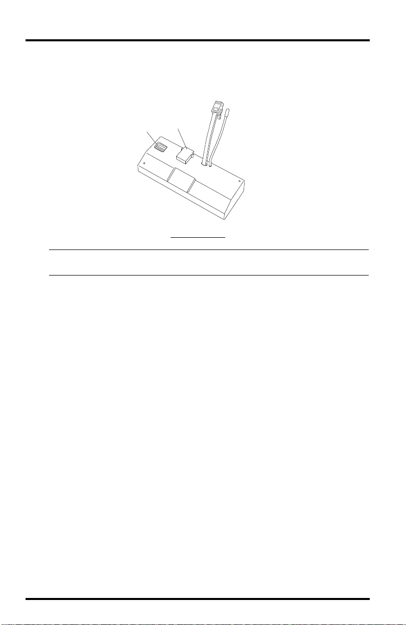
The ConsoleLink consists of a single unit as shown below.
ConsoleLink
Connector
WeatherLink
Dip
Switches
Note:
Y ou must also have an appropriate host weather station and a DavisTalk compatible receiver to
complete the system. See our latest catalog for a listing of DavisTalk compatible products.
Jack
THE C
ONSOLELINK
Antenna
OCATING THE CONSOLELINK
L
Try to position the DavisTalk compatible receiver(s) as close to the
ConsoleLink as possible. Here are typical maximum transmission ranges:
In the line of sight: 400 feet (240 m).
✦
✦
Through walls and ceilings: 100 to 200 feet (30 to 60 m).
Through trees and foliage: 100 to 200 feet (30 to 60 m).
✦
Radio transmission range is reduced by:
✦
Interior and exterior walls, trees and other foliage.
Metal reinforcements such as rebar and wire mesh in walls.
✦
✦
People in the vicinity of the receiver.
✦
Radio interference from wireless products such as 900 MHz cordless phones.
I
NSTALLATION
S
TEPS
The ConsoleLink comes already assembled; all you need to do is:
1. Attach the ConsoleLink to the host weather station, page 3.
If you wish, you can also attach a WeatherLink Data Logger, page 3,or
attach a ConsoleLink to a wireless weather station, page 4.
2. Set the transmitter ID code, page 5.
3. Power the ConsoleLink, page 6.
4. Test data transmission, page 6.
Page 2 ConsoleLink™
Page 3
TTACHING
A
THE
ONSOLE
C
L
INK
TO
THE
H
OST
W
EATHER
TATION
S
The ConsoleLink has a short cable with a modular connector (ConsoleLink
connector) on its free end. Attach the transmitter to the host weather station as
follows:
1. Remove power from your weather
station.
2. Nest the ConsoleLink into the
console base.
Power
Cord
Weather Station
Console
"WeatherLink"
Jack
3. Insert the ConsoleLink connector into
To Power
Adapter
A
TTACHING
Note: We recommend not to plug in the power cord at this time. The diagram above is for you to refer
ConsoleLink
Connector
"WeatherLink"
Pass-through Jack
C
THE
to when you power the ConsoleLink (see page 6).
ONSOLE
Antenna
Console
Base
L
INK
ConsoleLink
TO
THE
H
S
OST
the weather station “WeatherLink” jack as
shown.
TATION
TTACHING
A
A
W
EATHER
L
INK
D
ATA
OGGER
L
(O
PTIONAL
)
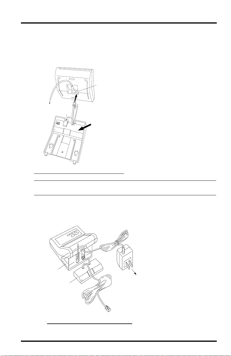
You can attach a WeatherLink data logger to the ConsoleLink as follows:
1. Remove power from the
weather station.
2. Nest the ConsoleLink into
the console base as shown in
the diagram above.
Power
ConsoleLink
inside console base
WeatherLink
(optional)
WeatherLink
External Cable
Connection
to Computer
Adapter
110 VAC
Power Outlet
3. Insert the ConsoleLink
connector into the weather
station “WeatherLink” jack.
4. Insert the WeatherLink
connector into the ConsoleLink “WeatherLink” jack
5. Reinstall the Console base
following the instructions in
your host station manual.
A
TTACHING
W
A
EATHER
L
C
INK
TO
THE
ONSOLE
L
INK
Attaching the ConsoleLink to the Host Weather Station Page 3
Page 4

Note: The WeatherLink will not fit in the base of the host station and must be positioned outside of
the console base as shown on page 3. Avoid putting undue pressure on the short cable plugged
into the ConsoleLink.
TTACHING
A
THE
ONSOLE
C
L
INK
TO
A
W
IRELESS
W
EATHER
You can attach a ConsoleLink to a wireless weather station as follows:
1. Remove power from the weather station.
2. Nest the ConsoleLink into the console base as shown in diagram A.
A
To
Power
Adapter
A
TTACHING
Weather Station
Console
SensorLink
Receiver
ConsoleLink
Mounting Base
C
THE
ONSOLE
L
INK
B
To
Power
Adapter
TO
ConsoleLink
(inside Mounting Base)
SensorLink
Receiver
WeatherLink
to Computer
W
IRELESS
W
A
EATHER
S
TATION
3. Insert the SensorLink connector into the weather station “Junction Box” jack.
4. Reinstall the console base following the instructions in your host station manual.
The SensorLink remains outside the console base.
5. Insert the WeatherLink connector into the ConsoleLink jack as shown in diagram B.
Both the WeatherLink and SensorLink remain outside the console base.
6. Adjust the SensorLink and ConsoleLink antennas to a vertical position outside the
console base.
7. Apply power once you make all the connections.
TATION
S
WeatherLink
Connection
Page 4 ConsoleLink™
Page 5

ETTING
S
THE
RANSMITTER
T
ID C
ODE
The ConsoleLink uses any of eight selectable ID codes (the default is ID Code
#1). The transmitter and receiver communicate with each other only if they are
both set to the same ID code. Use the default setting unless you have another
Davis wireless system operating nearby which you want to work separately
from the new system. The dip switch settings for the eight possible codes are
shown in the table below.
ID C
ODEDIP SWITCH
(default)
#1
1DIP S
WITCH
2DIP S
WITCH
off off off
3
#2 off off ON
#3 off ON off
#4 off ON ON
#5 ON off off
#6 ON off ON
#7 ON ON off
#8 ON ON ON
To change to another transmitter ID code:
✦
Flip dip switches 1, 2, and/or 3 on the transmitter to the desired position using the
table above.
The transmitter and receiver must use the same ID code to communicate.
If you change the ID code on the transmitter, then you must change the
ID Code on the receiver to correspond.
Dip Switches
UNIT ID
BEEP MODE
1234
ON
BEEP MODE
OFF
C
HANGING THE DIP SWITCHES
ON
Note:
Use Dip switch #4 for testing, not for ID codes. (See ‘Testing Data Transmission” on page 6.)
When SET is on, the unit beeps each time data is transmitted.
Setting the Transmitter ID Code Page 5
Page 6

OWERING THE CONSOLELINK
P
Before you apply power to the ConsoleLink, make sure that the proper connections are made. See pages 3-4 for connection options. Once you connect the
ConsoleLink, apply power to the console according to the weather station
manual. The weather station beeps once at power up and thereafter as follows:
✦
If there is no WeatherLink plugged into the ConsoleLink, the weather station
beeps once more, about eight seconds later. After another 25 seconds, the
ConsoleLink beeps once.
✦ If there is a WeatherLink plugged into the ConsoleLink, the weather station beeps
again twenty-three seconds later. Then, the ConsoleLink beeps twice within the
next five seconds.
✦ If there is a SensorLink plugged into the console you hear a total of five beeps. The
weather station beeps again twenty-three seconds later. Then the ConsoleLink
beeps twice within the next five seconds. Finally, the SensorLink beeps once.
TESTING DATA TRANSMISSION
To verify that the ConsoleLink transmits data, you need to set the unit to test
mode by moving dip switch #4 to the ON position. In this mode, the
ConsoleLink beeps each time the unit transmits data at about 2.5-second
intervals.
TROUBLESHOOTING
While the ConsoleLink T ransmitter can provide years of tr ouble-free operation,
occasional problems may arise. If you experience a problem, please check the
troubleshooting list below before calling the factory. If you are still unable to
solve the problem, call the factory at (510) 732-7814 for assistance.
Please do not return your unit for repair without prior authorization.
✦ The DavisTalk receiver is receiving erratic data.
Another Davis wireless system may be operating nearby on the same ID or ,
a cordless phone may be operating within 10 feet of the receiver. You can
try changing to a different ID code on both the receiver and the transmitter
or, try moving the phone.
✦ The DavisTalk receiver is not receiving any data.
The transmitter and the receiver may be too far apart or , something in their
path may be interfering, such as foliage, furnishings or, cordless phones.
Set the Test Mode on the transmitter to see if it is transmitting data.Try
moving the receiver closer to the transmitter or, vice versa or, eliminating
possible path interferences. Verify that both the ConsoleLink and the
receiver use the same ID code.
✦ The ConsoleLink does not transmit data.
Make sure that dip switch #4 is in Test Mode. If you cannot hear a beep,
disconnect the power to the weather station and start again.
Page 6 ConsoleLink™
Page 7

SPECIFICATIONS
✦ Transmit frequency—U.S. Model: 916.5 MHz, Overseas Model: 868.35 MHz
✦ ID codes—8 user selectable
✦ License—Low power, no license required
✦ Temperature range—32 to 140 °F (0 to 60°C)
Specifications Page 7
Page 8

FCC PART 15 CLASS B REGISTRATION WARNING
This equipment has been tested and found to comply with the limits for a class
B digital device, pursuant to Part 15 of the FCC Rules. These limits are
designed to provide reasonable protection against harmful interference in a
residential installation. This equipment generates, uses and can radiate radio
frequency energy and, if not installed and used in accordance with the instructions, may cause harmful interference to radio communications. However,
there is no guarantee that interference will not occur in a particular installation.
If this equipment does cause harmful interference to radio or television reception, which can be determined by turning the equipment off and on, the user is
encouraged to try to correct the interference by one or more of the following
measures:
✦ Re-orient or relocate the receiving antenna.
✦ Increase the separation between the equipment and receiver.
✦ Connect the equipment into an outlet on a circuit different from that to which the
receiver is connected.
✦ Consult the dealer or an experienced radio/TV technician for help.
Shielded cables and I/O cords must be used for this equipment to comply with
the relevant FCC regulations. Changes or modifications not expressly
approved in writing by Davis Instruments may void the user's authority to
operate this equipment.
Product Number: 7617 & 7617OV
Davis Instruments Part Number: 7395.067
ConsoleLink™ Installation Manual
Rev. A Manual (5/11/00)
Controlled Online: Weather Manuals:DavisTalk:ConsoleLink
This product complies with the essential protection requirements of the EC EMC Directive 89/336/EC.
© 2000 Davis Instruments Corp. All rights reserved.
3465 Diablo Avenue, Hayward, CA 94545-2778
510-732-9229 • Fax: 510-732-9118
E-mail: info@davisnet.com • www.davisnet.com
 Loading...