

Page 1
ELLULAR
C
ELEPHONE
T
NTRODUCTION
I
NTENNA
A
I
NSTALLATION MANUAL
K
IT
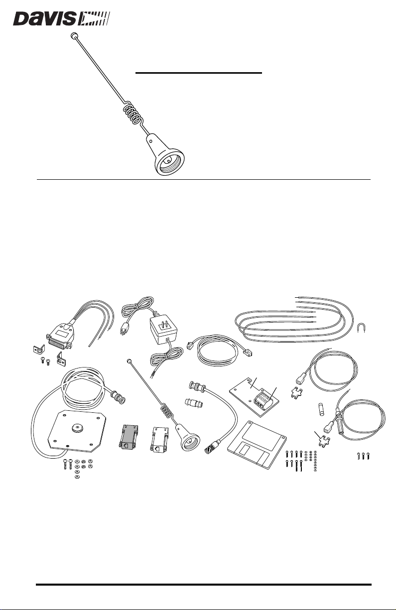
The Cellular Telephone Antenna Kit contains the materials necessary to connect a WeatherLink
®
data logger to a Motorola SMCT2 cellular telephone
modem (CTM). The SMCT2 CTM must be obtained from Motorola. See the
accompanying sheet for Motorola contact information.
C
OMPONENTS
The Cellular T elephone Antenna Kit includes the following components. Please
make sure you have all listed components before continuing.
CTM Power
Cable
2-Amp Power
Adapter
AOM Wires
Jumper
Power Connector
Brackets
#8 x 3/4" Machine Screws,
Washers, Lock Washers, & Nuts
Modular Cable
Antenna
Ground Plane &
Antenna Cable
WeatherLink
Radio/SR Modem
Adapter
✦
Antenna, 806-896 MHz 3dB, Omni-Directional
Ground Plane, with antenna base, antenna cable with BNC connector
✦
Terminal Plate, with 4-position terminal block and adhesive foam tape
✦
✦
WeatherLink Radio/SRModem Adapter
WeatherLink PC Radio Adapter
✦
WeatherLink
PC Radio
Adapter
BNC Adapter
Modem RF
Cable
Terminal
Modem
Configuration
Disk
Plate
Terminal
Block
10 A Fuse
Tab Adapter
#4 Machine Screws, Washers,
Star Washers, & Nuts
Battery Wires
#6 Sheet Metal Screws
Product #7652-003
Page 2
✦
BNC Adapter
✦
Power Adapter, 12V, 2A
Modem RF Cable, co-axial, BNC and Mini-UHF connectors, 12" (30 cm) long
✦
✦
CTM Power Cable, DB25 connector and cable
✦
Modular Cable, 6-conductor, 4' (1.2m) long
Two Tab Adapters
✦
✦
Two Battery Wires (1 red, with in-line fuse holder, 1 black)
✦
Three Alarm Output Module Wires (1 green, 1 yellow, 1 white)
Jumper Wire, yellow
✦
✦
Three #6 Sheet Metal Screws (for mounting modem bracket)
✦
Two #8-32 x 3/4" Machine Screws, Washers, Lock Washers, and Nuts (for mounting antenna)
✦
Two Power Connector Brackets and #6 Screws
✦
Two #4 x 3/8" Machine Screws and Two #4 x 3/4" Machine Screws, Washers, Star
Washers, and Nuts (for mounting hang-up cup)
Four #4 x 3/8" Machine Screws and Nuts (for mounting Timer on terminal plate)
✦
✦
Modem Configuration Disk
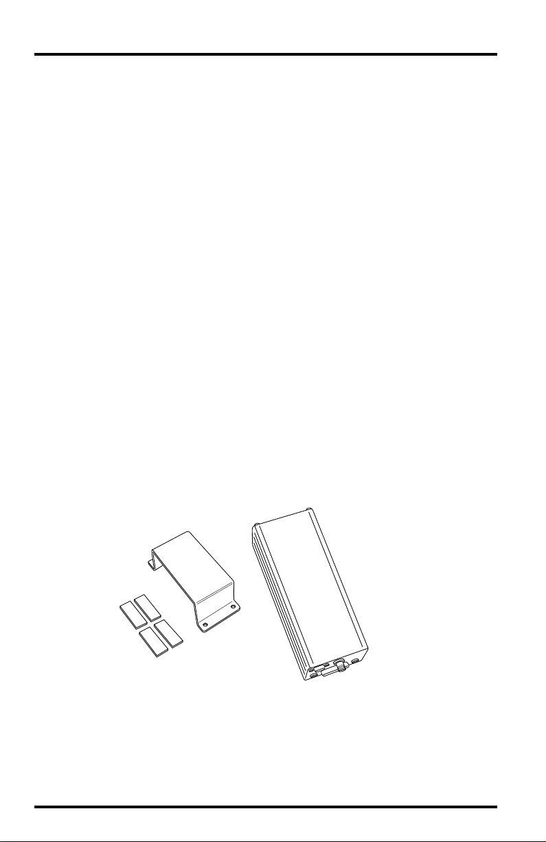
Motorola SMCT2 Cellular Telephone Modem Components
The Motorola SMCT2 CTM should include the following components, which
will be necessary for the installation.
Cellular Telephone
Modem
Mounting Bracket
and Adhesive Pads
✦
Cellular telephone Modem (S5692A)
✦
Mounting Bracket
4 Adhesive Pads
✦
The CTM should also include a power cable, two wire/fuse loops, one black
wire, and a hardware package, none of which is needed.
Page 2 Cellular Telephone Antenna Kit
Page 3

Power Components
You will need to supply power to the CTM site, using one of the following
options.
✦
If AC power is available at the CTM site, use the power adapter supplied with this
kit.
To power the CTM with solar power, use the Solar Power Kit (#7708) and 6.5-
✦
Amp-Hour Battery (#7711).
If solar power is used, it will be necessary to switch the power to the
phone so that it is on for only limited periods in order to conserve the
power drawn. Two alternatives are available:
Alarm Output Module (#7736)
✦
Timer (#7682)
✦
The Timer is recommended unless the Alarm Output Module is
being used for other purposes.
WeatherLink Components
You will need the following item from your WeatherLink package:
PC COM Port Adapter
✦
On older versions of the WeatherLink, this adapter was labelled AT
Adapter.
Optional Components
The following optional components may be necessary for your installation.
✦
Radio Surge Protector (#7681SSC)
If the CTM is located in an area where lightning strikes are a possibility,
use the Radio Surge Protector to provide surge protection between the
antenna and the CTM. Davis recommends the use of the Radio Surge
Protector in
Antenna Mounting Bracket (#7684)
✦
all installations
.
The hardware provided with the Antenna Kit enables you to mount the
antenna on the Sensor Mounting Arm (#7702). If you want to mount it
on a pole, post, or wall, use the Antenna Mounting Bracket.
Note: The CTM’s antenna should be located as high as possible and away from buildings and
other obstructions, if possible. It is best if the path between the antenna and the nearest phone company cell antenna is completely unobstructed (line-of-sight). Intervening
trees and other vegetation can reduce the signal intensity.
✦
Handset (Motorola #SL2504) and Hang-Up Cup Assembly (Motorola #SL9854)
If you wish to originate or receive voice calls at the weather station/
CTM site, you will need to order the handset and hang-up cup assembly
from Motorola. Consult the Motorola Contact and Parts Information
Sheet for more details.
Components Page 3
Page 4
p
OOLS
T
EQUIRED
R
In addition to the components listed above, you may need the following tools.
Please be sure you have everything you need before beginning the installation.
Phillips Screw Driver
✦
Slotted Screw Driver
✦
✦
Electric Drill with 7/32" (5.5 mm) and 1/8" (3 mm) drill bits
YPICAL
T
NSTALLATIONS
I
The illustrations below show three typical installations: AC-powered, solarpowered using the Timer, and solar-powered using the Alarm Output Module.
A list of steps for each installation type is provided.
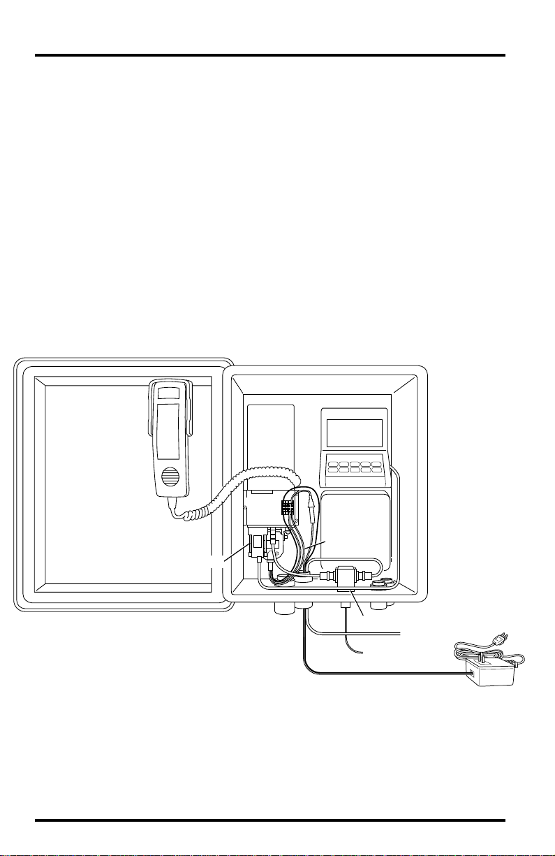
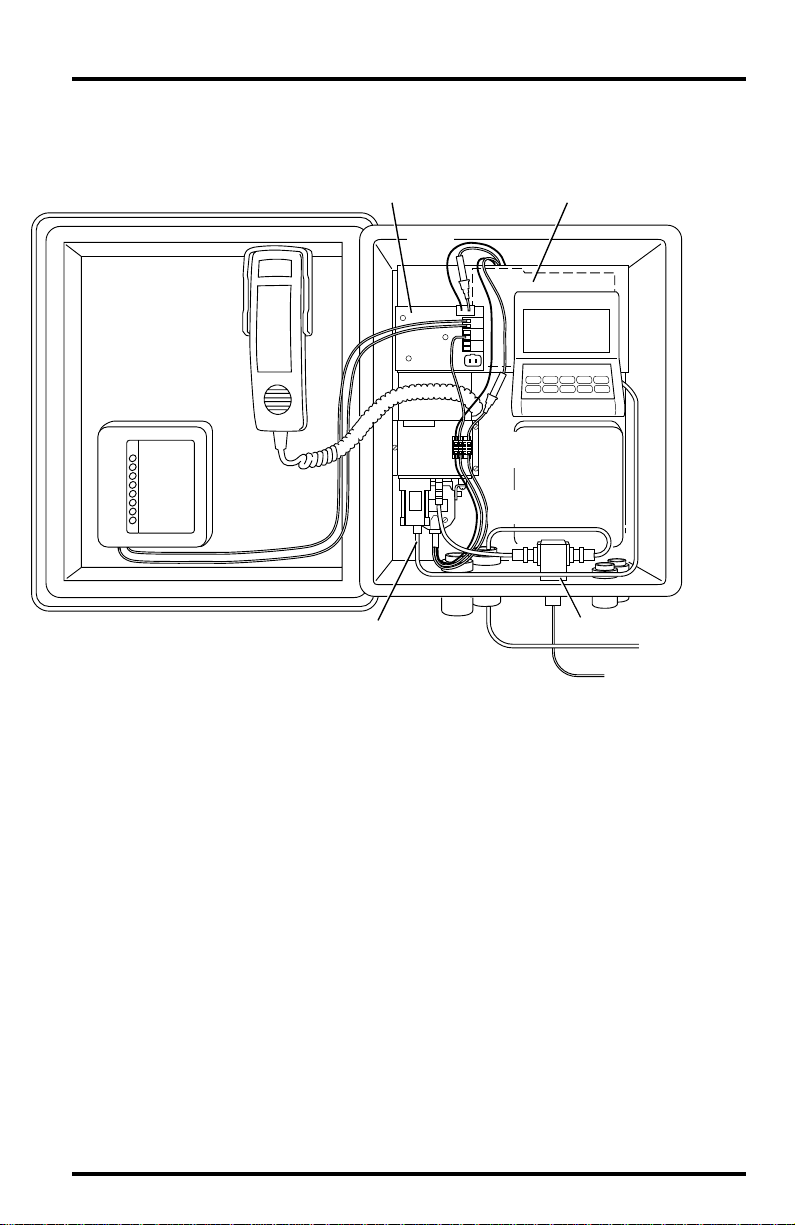
AC-Powered
The illustration below shows an AC-powered station and cellular telephone
modem (CTM).
Cell Phone
Handset
CTM
Console
Terminal
Block
Link Adapter
Sensor
Interface
Module
CTM Power
Cable
Radio Surge Protector (optional)
To Antenna
Protector Ground
+12 V
AC-Power
ter
Ada
You must complete the following steps for this installation.
1. Configure the CTM (see “Configuring The Cellular Telephone Modem” on page 8).
2. Install antenna (see “Installing Antenna” on page 11).
3. Install Radio Surge Protector (optional).
Consult the manual supplied with the Radio Protector for installation
instructions.
Page 4 Cellular Telephone Antenna Kit
Page 5
4. Install CTM (see “Installing Cellular Telephone Modem” on page 13).
5. Install terminal plate (see “Installing Terminal Plate/Timer” on page 15).
6. Connect AC-power wires (see “Connecting AC-Power Wires” on page 16).
Do not connect to AC power yet.
7. Install hand set and hang-up cups (optional; see “Installing Handset and Hang-Up
Cups” on page 20).
If you wish to originate or receive voice calls at the weather station/CTM
site, you will need to install the handset and hang-up cup assembly.
8. Check wiring.
Before you apply power to the system, review your wiring to make sure all
connections are correct and all wires firmly secured in the proper terminal.
9. Connect power to system.
Do not connect power until the rest of your installation is complete. Plug the
power adapter into a power outlet.
10.Finalize the installation by testing the installation (see “Finalizing the Installation” on
page 21).
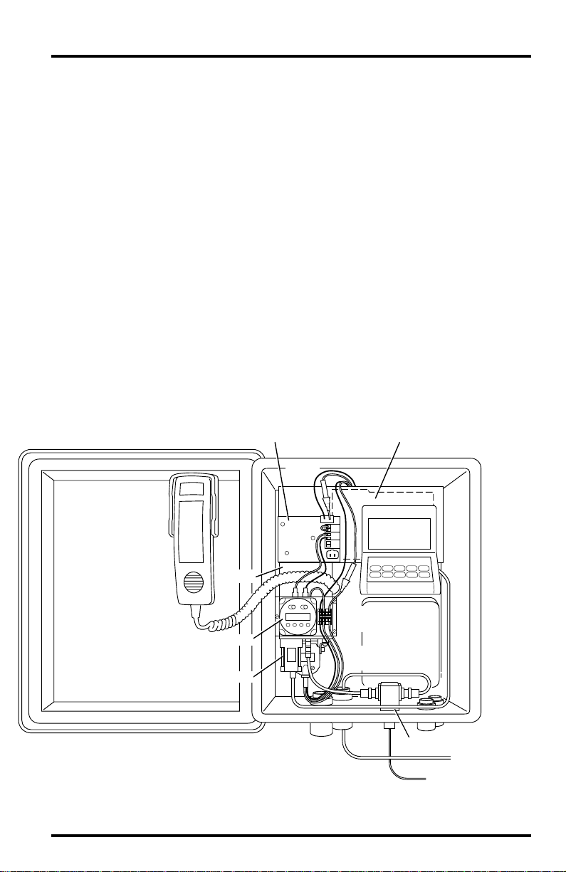
Solar-Powered Using Timer
The illustration below shows a solar-powered station and CTM using a Timer
for power conservation.
Regulator
Battery
In-Line
Fuses
Cell Phone
Handset
Console
CTM
Timer
Link Adapter
Terminal
Block
Interface
CTM Power
Cable
Sensor
Module
Radio Surge Protector (optional)
To Antenna
Protector Ground
You must complete the following steps for this installation.
Typical Installations Page 5
Page 6

1. Configure the CTM (see “Configuring The Cellular Telephone Modem” on page 8).
2. Install antenna (see “Installing Antenna” on page 11).
3. Install Solar Power Kit and 6.5-Amp-Hour Battery (see “Installing Solar Power Kit &
Battery” on page 12).
4. Install Radio Surge Protector (optional).
Consult the manual supplied with the Radio Protector for installation
instructions.
5. Install CTM (see “Installing Cellular Telephone Modem” on page 13).
6. Install terminal plate and Timer (see “Installing Terminal Plate/Timer” on page 15).
7. Connect Timer and battery wires (see “Connecting Timer and Battery Wires” on
page 17).
8. Install hand set and hang-up cups (optional; see “Installing Handset and Hang-Up
Cups” on page 20).
If you wish to originate or receive voice calls at the weather station/CTM
site, you will need to install the handset and hang-up cup assembly.
9. Check wiring.
Before you apply power to the system, review your wiring to make sure all
connections are correct and all wires firmly secured in the proper terminal.
10.Connect power to system.
Do not connect power until the rest of your installation is complete. Connect the
battery cable to B2 on the regulator circuit. Connect the solar panel cable to
B1 on the regulator circuit. Finally, insert the fuse into the in-line fuse holder
in the red battery wire.
11. Finalize the installation by programming the Timer and testing the system (see “Finalizing the Installation” on page 21).
Page 6 Cellular Telephone Antenna Kit
Page 7
Solar-Powered Using Alarm Output Module
The illustration below shows a solar-powered station and CTM using the
Alarm Output Module (AOM) for power conservation.
Battery
Console
Sensor
Interface
Module
Cell Phone
Handset
Alarm Output
Module (AOM)
Regulator
In-Line
Fuses
CTM
Terminal
Block
CTM Power
Cable
Link Adapter
Radio Surge Protector (optional)
To Antenna
Protector Ground
You must complete the following steps for this installation.
1. Configure the CTM (see “Configuring The Cellular Telephone Modem” on page 8).
2. Install antenna (see “Installing Antenna” on page 11).
3. Install Solar Power Kit and 6.5-Amp-Hour Battery (see “Installing Solar Power Kit &
Battery” on page 12).
4. Install Alarm Output Module.
Consult the manual supplied with the AOM for instructions. Make sure to
mount the AOM in the location shown above.
5. Install Radio Surge Protector (optional).
Consult the manual supplied with the Radio Protector for installation
instructions.
6. Install CTM (see “Installing Cellular Telephone Modem” on page 13).
7. Install terminal plate (see “Installing Terminal Plate/Timer” on page 15).
8. Connect Alarm Output Module and battery wires (see “Connecting Alarm Output Mod-
ule and Battery Wires” on page 19).
Typical Installations Page 7
Page 8
9. Install hand set and hang-up cups (optional; see “Installing Handset and Hang-Up
Cups” on page 20).
If you wish to originate or receive voice calls at the weather station/CTM
site, you will need to install the handset and hang-up cup assembly.
10.Check wiring.
Before you apply power to the system, review your wiring to make sure all
connections are correct and all wires firmly secured in the proper terminal.
11. Connect power to system.
Do not connect power until the rest of your installation is complete.
battery cable to B2 on the regulator circuit. Connect the solar panel cable to
B1 on the regulator circuit. Finally, insert the fuse into the in-line fuse holder
in the red battery wire.
12. Finalize the installation by programming the AOM and testing the installation (see
“Finalizing the Installation” on page 21).
C
ONFIGURING
As delivered by Motorola, the cellular telephone modem (CTM) is not compatible with your WeatherLink. Follow the instructions below to configure the CTM.
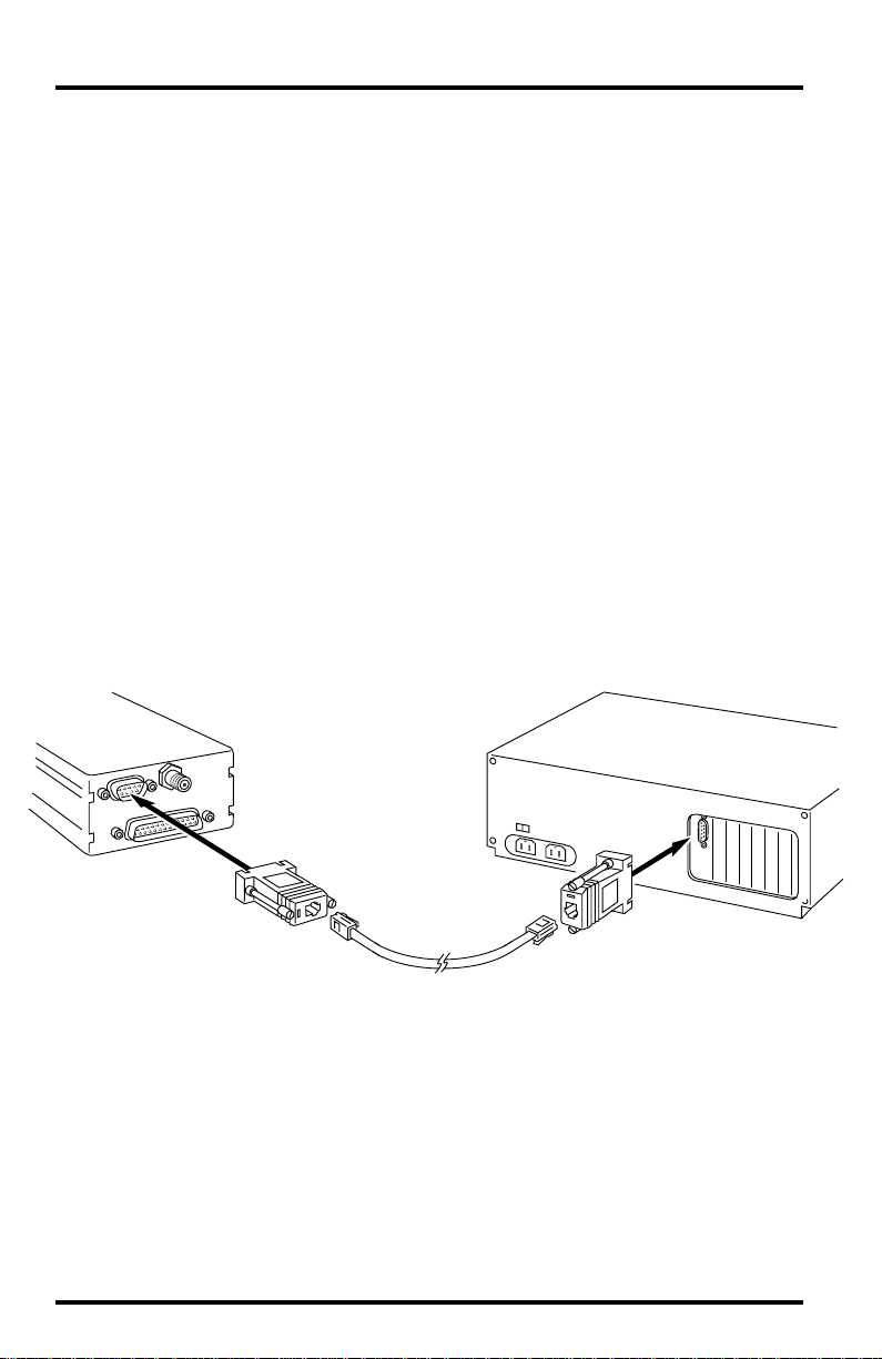
Connect the CTM to your Computer
Connect the CTM to your computer, as shown below.
T
HE
C
ELLULAR
T
ELEPHONE
M
ODEM
Connect the
Modem
(CTM)
PC Com
Port
PC RADIO
Adapter
PC COM Port
Adapter
Modular
Cable
1. Connect the PC COM Port Adapter to a serial port on your PC.
2. Connect one end of the modem cable to the PC COM Port Adapter.
3. Connect the PC RADIO Adapter to the DB9 connector on the CTM.
4. Connect the other end of the modem cable to the PC RADIO Adapter.
Page 8 Cellular Telephone Antenna Kit
Page 9
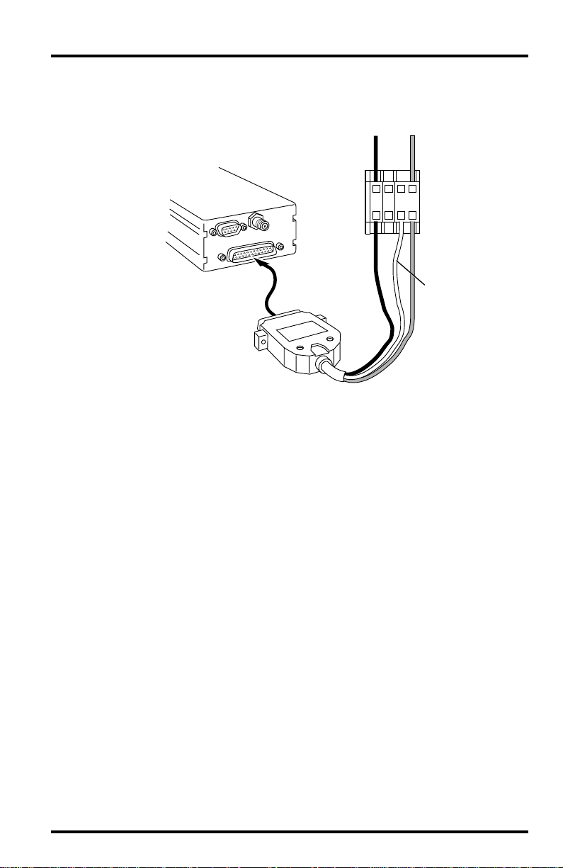
Power the CTM
Connect power to the CTM, as shown below.
AC-Power
Adapter Wires
_
+
Terminal
Block
RedBlack
Green
(PC RADIO Adapter
Not Shown)
Modem
(CTM)
CTM Power
Cable
1234
1. On one side of the terminal block, connect the black CTM power wire to terminal 1
(grey), the green CTM power wire to terminal 3 (orange), and the red CTM power wire
to terminal 4 (orange).
2. On the other side of the terminal block, connect the black power adapter wire to ter-
minal 1 (grey) and the red power adapter wire to terminal 4 (orange).
3. Plug the power adapter into a power outlet.
Run The Modem Configuration Program
Finally, use the supplied modem configuration program to configure the CTM.
1. Place the Modem Configuration Disk in your disk drive.
2. Choose Run from the File Menu (Windows 3.1) or the Start Menu (Windows 95).
Configuring The Cellular Telephone Modem Page 9
Page 10

3. Type A:\CONFIG and press Enter (or choose Ok).
The Wireless Configuration Program dialog box appears.
4. Select Cell Phone Modem from the Modem Type drop-down list.
5. Select the COM port to which the CTM is connected from the COM Port drop-down list.
If you don‘t know the COM port number, choose COM 1. If you get a program error when attempting to configure the CTM, try again using COM 2,
and so on, until you find the correct COM port setting.
6. If you fully understand the CTM’s AT command set and wish to configure the CTM differently than the default configuration, choose Advanced. You may then enter the
desired AT commands and choose Execute Command to execute the string. Choose
View Conf to view the CTM’s current configuration.
The default configuration should work in almost all installations; we do not
recommend using the Advanced setting option.
7. When finished, choose Configure.
The program will attempt to locate and configure your CTM. If you encounter an error, make sure you have selected Cell Phone Modem and then try
different serial ports until the configuration completes successfully.
Page 10 Cellular Telephone Antenna Kit
Page 11

NSTALLATION
I
Follow the instructions below to install the various components of your CTM.
In many cases, you will need to use the installation manual supplied with the
component for specific instructions.
Note:
Before beginning the installation, disconnect the cables attached in order to configure the CTM.
Installing Antenna
You may mount the antenna on either the Sensor Mounting Arm or on a pipe,
post, or wall using the Antenna Mounting Bracket (#7684).
Installing on Sensor Mounting Arm (SMA)
✦
Attach the antenna to the ground plane as shown below; screw on until
snug. Attach the ground plane to the SMA using the #8-32 x
flat washers, split lock washers, and hex nuts as shown below.
Note:
It may be necessary to drill one or two holes in the SMA to accommodate the antenna/
ground plane assembly . If so, use the holes in the ground plane as a guide and drill holes
using a 7/32" (5.5mm) drill bit.
¾
" screws,
Antenna
Ground
Plane
Ground Plane
Sensor Mounting Arm
If necessary, drill holes using
7/32" (5.5 mm) drill bit.
8-32 x 3/4" Screw
Flat Washer
Flat Washer
Lock Washer
#8 Hex Nut
Installation Page 11
Page 12

✦
Installing on Pipe, Post, or Wall
Mount the Antenna Mounting Bracket (AMB) on the pipe, post, or wall
according to the instructions supplied with the bracket. Attach the
antenna to the ground plane as shown below; screw on until snug.
Attach the ground plane to the AMB using the #8-32 x
¾
" screws, flat
washers, split lock washers, and hex nuts as shown below.
8-32 ¥ 3/4" Screw
Flat Washer
Antenna
Flat Washer
Split LockWasher
Ground
Plane
#8 Hex Nut
Antenna Mounting
Bracket
Lag Screws
(to mount on pipe,
use 11/2" U-bolts and
1
/4" nuts & washers)
Installing Solar Power Kit & Battery
Consult the manuals supplied with the appropriate component for instructions. Note the following, however, as you proceed with the installation.
Use tab adapters to attach wires to the battery.
✦
Before installing the battery, slide the tab adapters onto the terminals.
Attach the black battery wire (supplied with this kit) and the black wire
from the battery cable (supplied with the Solar Power Kit) to the tab
adapter connected to the ground (black) terminal. Attach the red battery
wire (suppplied with this kit) and the red wire from the battery cable
(supplied with the Solar Power Kit) to the tab adapter connected to the
positive (red) terminal. Make sure you have access to the free end of the
battery wires and the battery cable once the battery is installed.
Do not connect the solar panel or the battery to the regulator circuit.
✦
Make sure you have made no connections at B1 and B2 on the regulator
circuit before proceeding.
Page 12 Cellular Telephone Antenna Kit
Page 13

Installing Cellular Telephone Modem
Follow the instructions below to install the cellular telephone modem (CTM).
Install the station console/WeatherLink prior to installing the modem.
1. Connect the power cable to the DB-25 connector on the CTM, as shown below.
Power
Connector
Brackets
3/8" #6 Screws
2. Connect the WeatherLink Radio/SRModem Adapter to the DB-9 connector on the CTM.
3. Connect one end of the modem RF cable to the mini-UHF connector on the CTM.
4. Apply adhesive pads to the bracket according to the instructions supplied with the
CTM.
5. Attach the CTM and mounting bracket to the back of the Complete System Shelter or
the wall of a shed or other housing using the #6 sheet metal screws, as shown
below.
Modem
(CTM)
Complete System Shelter
Back Panel
(or shed wall)
Mounting
Bracket
Installation Page 13
Page 14

6. Connect the WeatherLink cable to the L1 connector on the WeatherLink Radio/SRModem Adapter.
7. Connect the free end of the modem RF cable to the BNC adapter or the EQUIPMENT
side of the Radio Surge Protector.
8. Connect the antenna cable to the BNC adapter or the ANTENNA side of the Radio
Surge Protector (routing the antenna cable through one of the strain reliefs at the
bottom of the shelter, if using the shelter).
WeatherLink
Radio/SR Modem
Adapter
From WeatherLink
Modem
(CTM)
Modem RF
Cable
WeatherLink
Data Logger
Console Base
BNC Adapter
Antenna
Cable
OR
Surge
Protector
(optional)
Page 14 Cellular Telephone Antenna Kit
Page 15

Installing Terminal Plate/Timer
If using the Timer, attach it to the terminal plate as shown below. Secure the ter minal plate to the mounting bracket using the adhesive tape on the back of the
plate, as shown below.
Timer (if used)
Terminal Plate
Adhesive
Foam Tape
Mounting
Bracket
Installation Page 15
Page 16

Connecting AC-Power Wires
Connect the CTM power cable and AC-power adapter to the terminal block, as
shown below.
1234
Red (+)
Terminal
Block
Black (-)
CTM
Black
CTM Power
Cable
✦ On one side of the terminal block, connect the black CTM power wire to terminal 1
Red
Green
(grey), the green CTM power wire to terminal 3 (orange), and the red CTM power
wire to terminal 4 (orange).
✦ On the other side of the CTM, connect the black wire from the power adapter or to
terminal 1 (grey) and the red wire to terminal 4 (orange).
Page 16 Cellular Telephone Antenna Kit
Page 17

Connecting Timer and Battery Wires
If using solar power in conjunction with the Timer, connect the system as
shown below.
Battery Cable
Supplied with
Solar Power Kit
Battery
Blk
_
Regulator
Red/Wht
5321
Timer
Modem
B3
B4
P1
B1
B2
Yel
Grn
Wht
Blk
Wht
Blk
Wht Blk
1234
Blk
In-Line
Fuse
RedBlack
Terminal
Block
RedBlack
Green
Red
Red
Power-Conserving
(operating) Position
Power-Up & Test
Position
+
Tab Adapters
CTM Power
Cable
✦ On one side of the terminal block, connect the black battery wire to terminal 1
(grey), the red/white Timer wire to terminal 2 (green), and the red battery wire to
terminal 4 (orange).
Installation Page 17
Page 18

✦ On the other side of the terminal block, connect the black CTM power wire to ter-
minal 1 (grey), the green CTM power wire to terminal 3 (orange), and the red CTM
power wire to terminal 4 (orange).
The green wire will need to be moved to terminal 2 (green) after you
have tested the installation. Connecting the wire to terminal 3 bypasses
the “power-saver” mode and insures power is applied simultaneously to
the red and green CTM power wires.
✦ Connect the white and black wires from the Timer to the Wht and Blk terminals
(respectively) at B4 on the regulator circuit.
✦ Jumper together the two terminals (Yel and Grn) at B3 on the regulator circuit
using the jumper wire.
Page 18 Cellular Telephone Antenna Kit
Page 19

Connecting Alarm Output Module and Battery Wires
If using solar power in conjunction with the Alarm Output Module (AOM),
connect the system as shown below.
Battery Cable
Supplied with
Solar Power Kit
Battery
Blk
_
Regulator
+
_
B
Contacts
Alarm Output
Module
Modem
B4
Yel
B2
Yel
B3
Grn
Wht
Blk
Wht
P1
Blk
B1
Wht
Blk
Red
Red
+
Tab Adapters
In-Line
Fuse
Grn
Wht
RedBlack
Terminal
1234
Block
Power-Conserving
(operating) Position
RedBlack
Power-Up & Test
Position
Green
CTM Power
Cable
✦ On one side of the terminal block, connect the black battery wire to terminal 1
(grey), the red/white Timer wire to terminal 2 (green), and the red battery wire to
terminal 4 (orange).
Installation Page 19
Page 20

✦ On the other side of the terminal block, connect the black CTM power wire to ter-
minal 1 (grey), the green CTM power wire to terminal 3 (orange), and the red CTM
power wire to terminal 4 (orange).
The green wire will need to be moved to terminal 2 (green) after you
have tested the installation. Connecting the wire to terminal 3 bypasses
the “power-saver” mode and insures power is applied simultaneously to
the red and green CTM power wires.
✦ Connect one end of the yellow AOM wire to the Y el terminal at B3 on the regulator
circuit. Connect the other end to the positive (+) terminal at B on the AOM.
✦ Connect one end of the green AOM wire to the Grn terminal at B3 on the regulator
circuit. Connect the other end to the negative (-) terminal at B on the AOM.
✦ Connect one end of the white AOM wire to the Wht terminal at B4 on the regula-
tor circuit. Connect the other end to terminal 2 (green) on the terminal block, on
the same side as the power wires.
Installing Handset and Hang-Up Cups
If you wish to originate or receive voice calls at the weather station/CTM site,
install the handset and hang-up cup as shown below.
Note:If you install a handset you must not turn power off at the handset when leaving the station
because this overrides the Timer or Alarm Output Module control. The handset power must be
on for the “power saver” switching to “wake up” and receive calls from the WeatherLink software.
Installing the Handset
✦
Insert the phone plug on the end of the handset cable into the jack on the
side of the CTM.
✦ Installing the Hang-Up Cups in Complete System Shelter (CSS)
Use the cup as a guide and drill holes in the upper right corner of the CSS
door with a
⅛" (3 mm) drill bit. Secure the cup using the #4 screws,
washers, star washers, and nuts as show below . Use the #4 x
the two lower holes and the #4 x
⅜" screws in the two upper holes. Make
sure the cup is oriented correctly, with the white bumper at the top.
¾" screws in
#4 x 3/8" Screw
and Washer
(2 upper holes)
#4 Star Lock
Washer and Nut
#4 x 3/4" Screw
and Washer
(2 lower holes)
Hang-Up
Cup
Page 20 Cellular Telephone Antenna Kit
Page 21

✦ Installing the Hang-Up Cups on Wood Wall (of Shed or Similar Structure)
Use #6 x
¾" wood screws to secure the cup assembly in place, as shown
below.
#6 x 3/4" Wood Screws
FINALIZING THE INSTALLATION
The sections below detail the final steps that must be taken to complete the
installation.
Test Cell Phone
To insure that the CTM is working properly, test it. If you have a handset place
a call. If you do not have a handset, attempt to call the station using the WeatherLink software (try running the Bulletin). Consult the WeatherLink manual
for instructions.
Move Green CTM Power Wire (Solar Power/Battery Installations Only)
Once you are sure the cellular phone/CTM is working, move the green CTM
power wire from terminal 3 (orange) on the terminal block to terminal 2
(green).
Note:If power is completely removed from the CTM, the green CTM wire should be moved back to ter-
minal 3 before power is restored. Once power is restored, move the green wire back to
terminal 2. If this procedure is not followed, the CTM will occasionally power up in a nonresponding state.
Terminal
1234
Green
Block
Power-Conserving
(operating) Position
Power-Up & Test
Position
Finalizing the Installation Page 21
Page 22

Test and Program Timer (Timer Installations Only)
Manually set the Timer on and make sure the CTM is able to receive a call.
Manually set the Timer off and make sure the CTM does not answer a call.
Finally, program the Timer to enable the CTM. Consult the instructions supplied with the Timer for details.
Set AOM Jumpers and Test AOM (AOM Installations Only)
Insert jumper B from J5 on the AOM into pin jack 13 at J3 (consult the AOM
manual for more details). Close contact B (if the LED to the right of contact B is
lit, the contact is closed) by moving the jumper at J7 to Normally-Closed (if
necessary) and make sure the CTM is able to receive a call. Open contact B (if
the LED to the right of contact B is unlit, the contact is open) by moving the
jumper at J7 to Normally-Open (if necessary) and make sure the CTM does not
answer when called. When finished testing, move the jumper at J7 back to the Nor-
mally-Open position.
Insure Handset Power On
If you install a handset you must not turn power off at the handset when leaving the station because this over-rides the Timer or Alarm Output Module control. The handset power must be on to enable the “power saver” switching to
“wake up” the CTM and receive calls from the WeatherLink software.
POWER CONSERVATION MODE
If the cell phone is operating on solar/battery power, the Timer or AOM will be
used to switch the voltage on the green CTM power wire (“Ignition Detect”),
causing the CTM to “wake up” and turn on (referred to as enabling the CTM).
The CTM will not answer any incoming call unless the Timer or the AOM
enables it.
✦ AOM Power Saving
The AOM enables the CTM at 5 minutes past each even-numbered hour
(using the station console’s clock) and keeps it enabled for 4 minutes.
When a call is received, the CTM remains enabled during the call and for
2 minutes after the last communication is complete.
✦ Timer Power Saving
The user may set the Timer to any desired intervals. Any call in progress
when the Timer switches off will continue normally until hang-up.
✦ Disabling Power Saving
To disable power saving entirely, leaving the CTM on at all times, move
the green CTM power wire from terminal 2 (green) to terminal 3
(orange) on the terminal block.
Page 22 Cellular Telephone Antenna Kit
Page 23

CHARGE BUDGET
When using the CTM in a solar/battery-powered station, one must limit the
power drawn by the CTM. The means limiting the time that the CTM is on,
enabled to receive calls, and limiting even more severely the duration of calls.
The worksheets below enable you to calculate the charge drain per day and the
charge gain per day (from the solar panel). Comparison of these two numbers
will give you an idea of how long you may use the CTM before draining the
power supplied by the solar panel.
Charge Drain per Day
The worksheet below enables you to calculate the charge drain per day for various power on and transmission times.
COMPONENT CURRENT TIME ON DRAIN LINE
(AMPS)(MIN/DAY)(AMP-MIN)
Console, SIM/junction box & WeatherLink ______ 1440 ______ A
Alarm Output Module/Timer ______ ______ ______ B
CTM On 0.350 ______ ______ C
CTM Transmitting 1.300 ______ ______ D
Total System Drain per Day = A+B+C+D: ______ Amp-min
For each system component, write the amount of current drawn (in Amps) in
the Current column and the number of minutes per day the component is “on”
in the Time On column. Multiply the curr ent drawn by the number of minutes
to determine the drain caused by that component each day. Add the individual
drain figures together to determine the total drain per day for the entire system.
Consult the following for an explanation of worksheet lines A, B, C, and D.
✦ Line A (Console, SIM/junction box & WeatherLink)
The Weather Monitor II, with junction box and WeatherLink, draws 16
mA (0.016A) continuously (1440 minutes per day). The GroWeather,
Energy EnviroMonitor, and Health EnviroMonitor, with sensor interface
module (SIM) and WeatherLink, draw 20 mA (0.020A) continuously
(1440 minutes per day).
✦ Line B (Alarm Output Module/Timer)
The Alarm Output Module draws 9 mA (0.009A) continuously (1440
minutes per day). The Timer current may be considered negligible (0)
when the Timer is off (that is, its r elay is not energized). The Timer draws
12 mA (0.012A) when it is on (that is, the relay is closed).
✦ Line C (CTM On)
When the CTM is on (enabled), it draws 350 mA (0.35A).
Note:The Alarm Output Module enables the CTM for a minimum of 48 minutes every day (4
minutes each even-numbered hour). The timer enables the CTM for the amount of time
for which you have it set.
Charge Budget Page 23
Page 24

✦ Line D (CTM Transmitting)
The CTM draws an additional 1300 mA (1.3A) when transmitting.
Charge Drain per Day Example
The example worksheet shown below illustrates the power drain for a
GroWeather, using the Timer to turn the cell-phone on for six four-minute periods each day. It assumes that one five-minute call is made each day to read out
the data.
C
OMPONENT CURRENT TIME ON DRAIN LINE
(AMPS)(MIN/DAY)(AMP-MIN)
Console, SIM/junction box & WeatherLink 0.020 1440 28.8 A
Alarm Output Module/Timer 0.012 24 0.3 B
CTM On 0.350 24 8.4 C
CTM Transmitting 1.300 5 6.5 D
Total System Drain per Day = A+B+C+D: 44.0 Amp-min
Page 24 Cellular Telephone Antenna Kit
Page 25

Charge Gain per Day
The worksheet below enables you to calculate the average charge that the solar
panel provides to the battery each day for various day lengths and peak solar
irradiance values.
F
ACTOR VALUE LINE
Panel Current at 1000 W/m
Peak Solar Irradiance ______ W/m
2
______ Amps E
2
F
Day Length ______ hours G
”Cloud” Factor ______ H
Total Gain per Day = (E*F/1000)*0.6*(G*60)*H: _______ Amp-min
Enter the information into each column and then use the formula to calculate
the total gain for the day. The 0.6 factor includes battery efficiency and the integration of the solar cosine effect over the day. The total gain per day formula,
therefore, represents the following calculation: (rated panel current) x (peak
solar irradiance/1000) x (battery efficiency and solar cosine effect factor) x (day
length in minutes) x (”cloud” factor).
✦ Line E (Panel Current at 1000 W/m
2
)
The charging current provided by the solar panel when solar irradiance
is 1000 Watts per square meter. The panel included with the Davis Solar
Power Kit provides 0.6 Amp at 1000 W/m
✦ Line F (Peak Solar Irradiance)
The solar irradiance at solar noon at the station site, in W/m
✦ Line G (Day Length)
2
.
2
.
The length of the day, in hours.
✦ Line H (“Cloud” Factor)
A multiplier which you may use to account for cloudiness or other factors which may limit the sunlight reaching the panel throughout the day.
For example, a factor of 1.0 would represent an extended period with no
clouds. Note that even during cloudy conditions at least 20% of the solar
radiation usually gets through.
The example worksheet below illustrates the calculation.
F
ACTOR VALUE LINE
Panel Current at 1000 W/m
Peak Solar Irradiance 1000 W/m
2
0.6 Amps E
2
F
Day Length 10 hours G
”Cloud” Factor 0.75 H
Total Gain per Day = (E*F/1000)*0.6*(G*60)*H: 148.5 Amp-min
Charge Budget Page 25
Page 26

SCHEMATICS
12 V
2A
4A
Red
Blk
AC-Power Schematic
Red
Green
Modem
Blk
Battery
Battery
Red
Blk
Red
Blk
Red
Regulator
4 A
Blk
Solar
Panel
Red Red
4 A
Blk Blk
Solar
Panel
B3
B4
Regulator
B3
B4
10 A
2
Wht
Blk
1
Solar-Powered Using Timer Schematic
AOM
Contact B
_
+
10 A
Yel
Grn
Solar-Powered Using AOM Schematic
3
5
Wht
Red/
Wht
Initial power up and test
connection
Final test and operation
connection
Initial power up and test
connection
Final test and operation
connection
Red
Grn
Blk
Red
Grn
Blk
Modem
Modem
Page 26 Cellular Telephone Antenna Kit
Page 27

Schematics Page 27
Page 28

Product Numbers: 7652-003
Davis Instruments Part Number: 7395-124
Cellular Telephone Antenna Kit
Rev. A Manual (7/8/99)
This product complies with the essential protection requirements of the EC EMC
Directive 89/336/EC.
WeatherLink is a registered trademark of Davis Instruments Corp.
© Davis Instruments Corp. 1997. All rights reserved.
 Loading...