

Page 1
®
*360RGXOH
,QVWDOODWLRQ0DQXDO
for 'ULYH5LJKW
This manual provides the instructions necessary to install the DriveRight
GPS Module.
Refer to the DriveRight 600 User’s Guide and the DriveRight software help
for instructions on how to configure and use your GPS Module.
Note: The GPS Module is only compatible with the DriveRight 600. It cannot be used
with older DriveRight devices.
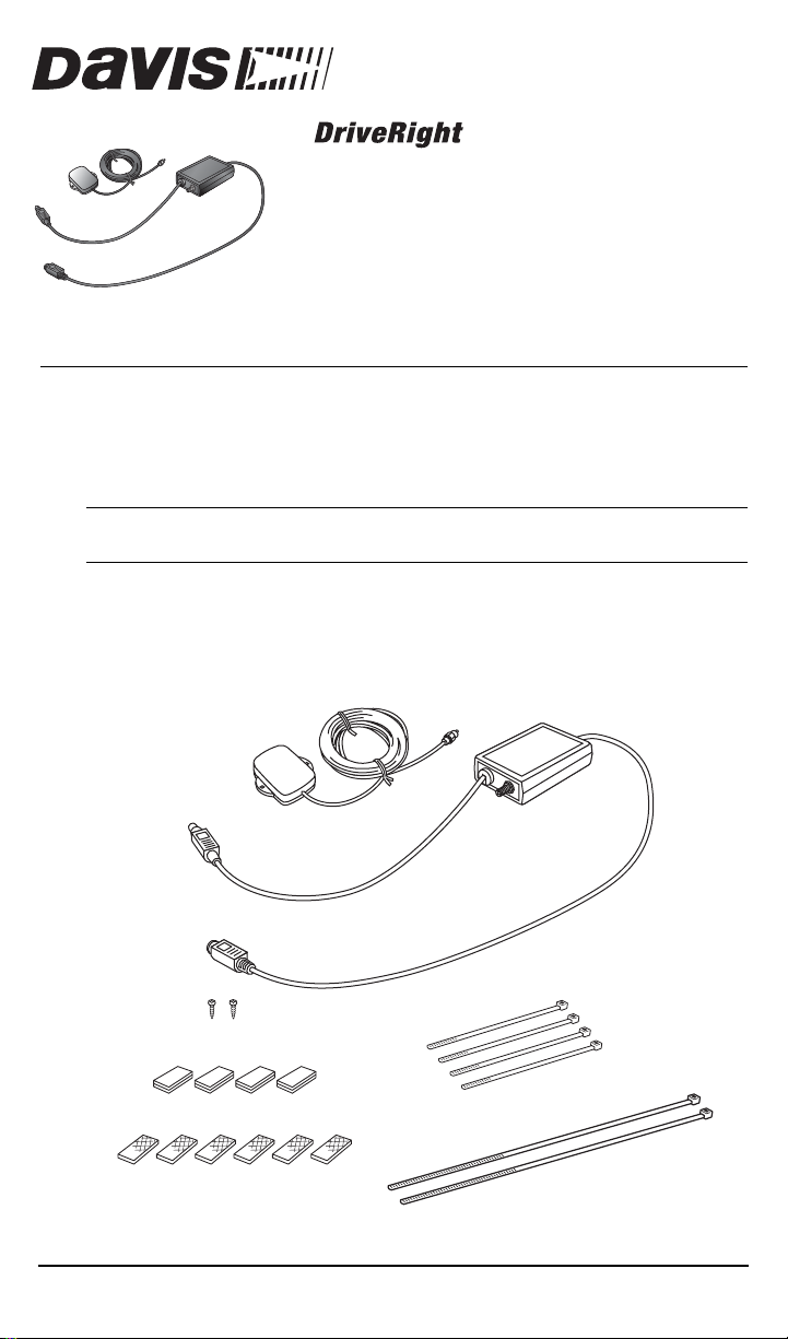
GPS Components and Mounting Hardware
The GPS Module should come with the all the components and mounting
hardware sho wn below:
GPS Antenna
#4 x 3/8" Pan Head Self-Tapping Screws (2)
Velcro® Tape (4 pair)
Double-Sided Foam Tape (6 strips)
GPS Module
5.5" Cable Ties (4)
12" Cable Ties (2)
Product # 8157
Page 2
Installing the GPS Module
Installing the GPS Module
1. Mount the GPS Module under the dashboard of the vehicle.
2. Secure the GPS Module in place usin g the pr ovided cable ties, velcr o tape,
or double-sided tape.
Installing the GPS Antenna
1. Mount the GPS antenna on top of the dashboard, on the roof of the
vehicle, or on the truck.
• Locate the antenna so that it has a clear view of the sky. Any metal
obstructions may interfere with satellite reception.
• The antenna must be at least three (3) feet away from any cellular or
CB antenna. Clos e proximity to a transm itt i n g ant e nn a ma y de gr ade
or disrupt GPS reception.
2. Secure using two screws, double-sided tape, velcro, or magnetic
mounting.
• To use the magnetic mount you must remove the aluminum base
plate to expose the antenna’s neodymium magnets.
3. Route the antenna cable to the GPS Module.
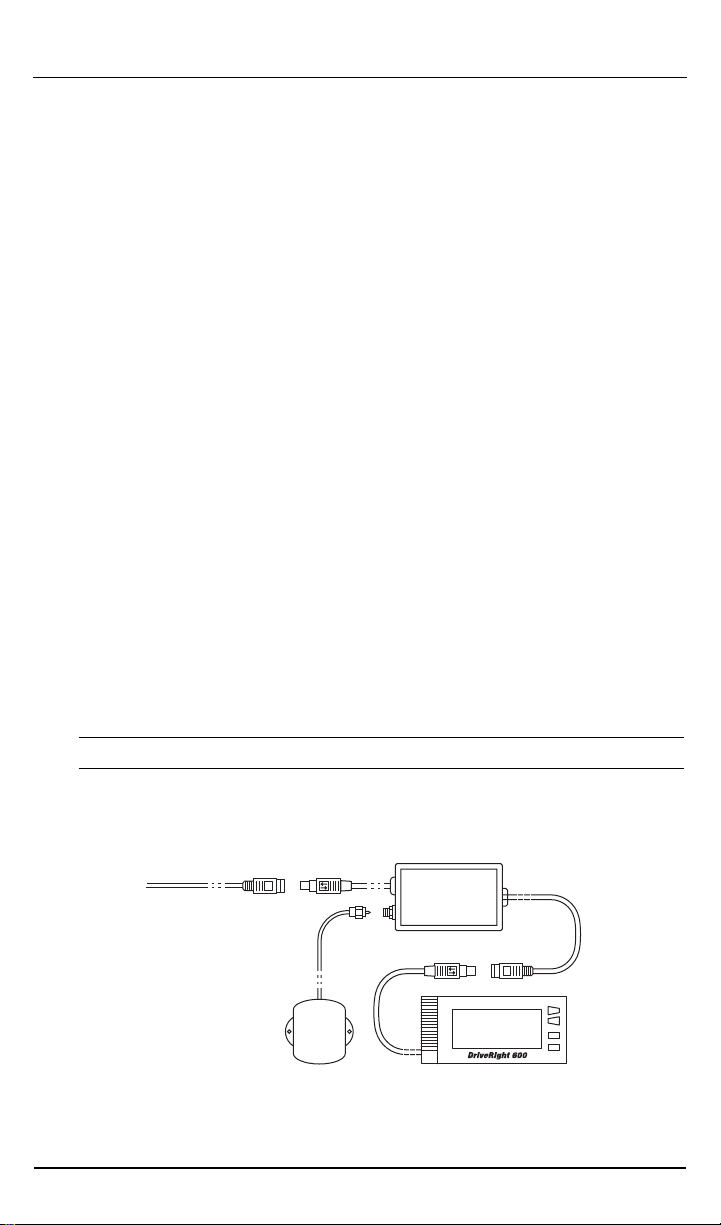
Making Connections
Refer to the installation diagram below to connect your GPS Module.
1. Connect the GPS Antenna to the GPS Module.
2. Connect the GPS Module to the DriveRight harness cable using the
DriveRight 600 adapter cable.
3. Connect the GPS Module to the DriveRight 600.
Note: GPS must be enabled via DriveRight software for the module to function.
Installation Diagr am
DriveRight 600
Adapter Cable
Page 2 GPS Module Installation Manual
GPS Module
DriveRight 600 DisplayGPS Antenna
Page 3

GPS Module Specifications
General GPS Specific a t ions
GPS Module Specifications
Mechanical
Environmental
Power
Interface
Cable Length
Size: 3.8” x 2.4” x 0.9” (97 x 61 x 23 mm)
Weight: 11 oz (0.3 kg)
Operating Range: -4°F to +140° F (-2 0°C to +6 0°C)
Storage Range: -40°F to +185°F (-40°C to +85°C)
Input: +12Vdc to +16 Vdc regulated, 80 mA max
Memory Backup: lithium cell, estimated 5 year service life
GPS Module-to-adapter cable: male 8-pin Mini-DIN
GPS Module-to-DriveRight 600: female 8-pin Mini-DIN
GPS Antenna: female SMA
GPS Module-to-adapter cable: 12” (300 mm)
GPS Module-to-DriveRight 600: 22” (570 mm)
GPS Receiver Specifications
Basic
Accuracy
Dynamic Limits
Startup Time To
First Locati on
Fix
Reacquisition
Time
Channels: 12 parallel
Frequency: 1575.42 MHz (L1)
Positiion: 25 m SEP without selective ability (SA), 100 m 2 DRMS with SA
(95%)
Velocity: 0.04 mph (0.02 m/s) without SA
Acceleration: 4 G max
Jerk: 5 m/s
DriveRight unplugged for 0 hours = 30 seconds
DriveRight unplugged for more than 0, less than 4 hours = 60 seconds
DriveRight unplugged for more than 4, less than 8 hours = 90 seconds
DriveRight unplugged for more than 8, less than 24 hours = 120 seconds
DriveRight unplugged for more than 24 hours =180 seconds
After 60 second signal obstruction: 5 seconds
Internal: <1.0 second
3
GPS Antenna Specifications
Mechanical
Environmental
Power
Cable
Performance
Size: 2.3” x 1.9” x 0.55” (58 x 48 x 14 mm)
Weight: 2.3 oz (0.065 kg)
Operating Range: -22°F to +185°F (-30°C to +85°C)
Storage Range: -40°F to +194°F (-40°C to +90°C)
Input: +3 Vdc regulated, 12 mA ± 2 mA
Type: Coaxial RG-174
Length: 16 feet (5 m)
Connector: male SMA
Frequency: 1575.42 MHz (L1); Gain: 25 dB (min); Output Impedance: 50
Ohms
GPS Module Installation Manual Page 3
Page 4

Contacting Davis Technical Support
If you have questions, or encounter problems installing or operating your
GPS Module, please contact Davis Technical Support.
Note: Please do not return items to the factory for repair without prior authorization.
Phone Suppor t
(510) 732-7814 – Monday – Friday, 7:00 a.m. – 5: 30 p.m. Pacific T ime.
(510) 670-0589 – Fax to Technical Support.
Email Suppor t
support@davisnet.com – E-mail to Technical Support.
info@davisnet.com – E-mail to Davis Instruments.
Web Support
www.davisnet.com – Copies of User Manuals are available on the
“Support” page. Watch for FAQs and other updates.
FCC Part 15 Class B R egistratio n Warning
This equipment has been tested and found to comply with the limits for a Class B digital device, pursuant
to Part 15 of the FCC Rules. These limits are designed to provide reasonable protection against harmful
interference in a residential installation. This equipment generates, uses, and can radiate radio frequency
energy and, if not installed and used in accordance with the instructions, may cause harmful interference
to radio communications.
However, there is no guarantee that interference will not occur in a particular installation. If this equipment
does cause harmful interference to radio or television reception, which can be determined by turning the
equipment on and off, the user is encouraged to try to correct the interference by one or more of the following measures:
• Reorient or relocate the receiving antenna.
• Increase the separation between the equipment and receiver.
• Connect the equipment into an outlet on a circuit different from that to which the receiver is connected.
• Consult the dealer or an experienced radio/TV technician for help.
Changes or modification not expressly approved in writing by Davis Instruments may void the warranty
and void the user's authority to operate this equipment.
Product Number: 8157 Davis Instruments Part Number: 7395.190
GPS Module Installation Manual
Rev B (June 23, 2003)
This product complies with the essential protection requirements of the EC EMC Directive 89/336/EC.
The term "IC:" before the radio certification number only signifies that Industry of Canada technical
specifications were met.
Copyright © 2002-2003 Davis Instruments Corp. All rights reserved.
3465 Diablo Avenue, Hayward, CA 94545-2778 U.S.A.
510-732-9229 • Fax: 510-732-9188
E-mail: info@davisnet.com • www.davisnet.com
 Loading...