

Page 1
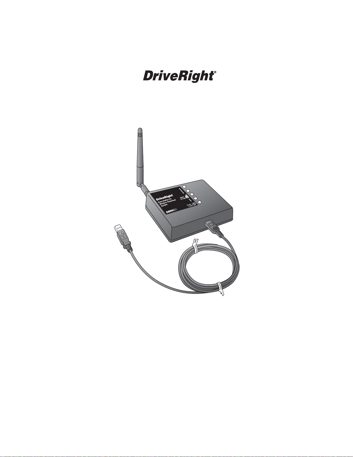
Base Station
for Wireless Download System
Installation Manual
Includes:
Base Station for Wireless Download System (#8130)
For Use with:
Wireless On-Board Module (#8129)
Configuration Cable for Wireless On-Board Module
(#8131)
Page 2

Regulatory Compliance
CE EC EMC Compliance
This product complies with the essential protection requirements of the EC EMC Directive 89/336/EC.
FCC Part 15.247
FCC ID: OUR-XBEEPRO
IC RSS-210
IC ID: 4214A-XBEEPRO
FCC Part 15 Class B Registration Warning
This equipment has been tested and found to comply with the limits for a Class B digital device, pursuant to Part 15 of the
FCC Rules. These limits are designed to provide reasonable protection against harmful interference in a residential installation. This equipment generates, uses, and can radiate radio frequency energy and, if not installed and used in accordance
with the instructions, may cause harmful interference to radio communications.
However, there is no guarantee that interference will not occur in a particular installation. If this equipment does cause harmful interference to radio or television reception, which can be determined by turning the equipment on and off, the user is
encouraged to try to correct the interference by one or more of the following measures:
• Reorient or relocate the receiving antenna.
• Increase the separation between the equipment and receiver.
• Connect the equipment into an outlet on a circuit different from that to which the receiver is connected.
• Consult the dealer or an experienced radio/TV technician for help.
Changes or modification not expressly approved in writing by Davis Instruments may void the warranty and void the user's
authority to operate this equipment.
For Products: #8130 Rev. A (9/1/06)
Davis Instruments Part Number: 7395.223
Base Station for Wireless Download Installation Manual
© Davis Instruments Corp. 2006. All rights reserved.
DriveRight
Industries, Manchester, NH.
®
is a registered trademark of Davis Instruments Corp. Velcro® is a trademark of Velcro
3465 Diablo Avenue, Hayward, CA 94545-2778 U.S.A.
510-732-9229 • Fax: 510-732-9188
E-mail: info@davisnet.com • www.davisnet.com
Page 3
Base Station for Wireless Download
System Installation
The Base Station for Wireless Download System is one of three products that
work together to give your DriveRight fleet the ability to download data
directly from the DriveRight devices to the FMS database in the fleet office,
without any actions by your fleet drivers. With this system, there is no need
for the drivers to carry the DriveRight device or SmartCard into the fleet
office. The data moves wirelessly from the vehicle to the FMS database.
This manual provides the instructions necessary to install the wireless Base
Station (#8130) to a computer. Refer to the DriveRight Fleet Management
Software Online Help for instructions on how to configure the Base Station
and Wireless On-Board Modules for use with your fleet.
Wireless System Overview
The Wireless System consists of three products:
• The Wireless On-Board Module (#8129) (requires #8127 GPS/Wireless
Interface Module)
• The Base Station for Wireless Download System (#8130)
• The Configuration Cable for Wireless On-Board Module (#8131)
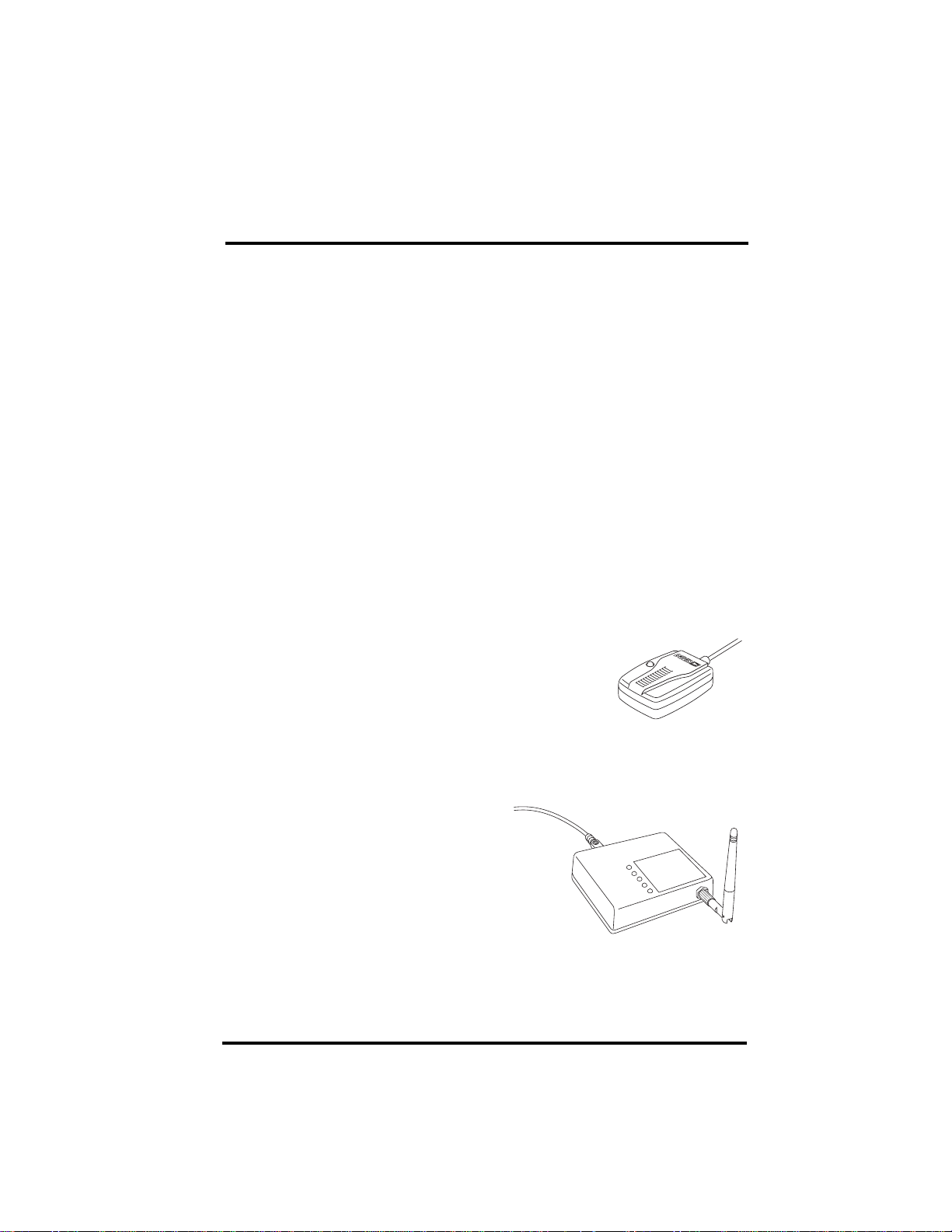
Wireless On-Board Module (#8129)
This module installs in the vehicle and connects to
the DriveRight device through the GPS\Wireless
Interface Module (#8127). Once the vehicle is parked
in the fleet parking lot, this module communicates
with a Base Station (#8130) and moves the
DriveRight data to the FMS database.
Base Station for Wireless On-Board Module
(#8130)
The Base Station connects to a
computer running FMS via a USB
connection. It communicates with all
the Wireless On-Board Modules
(#8129) installed in your fleet and
moves the data from the DriveRight
devices to the FMS database. Using
FMS, this operation can be
performed daily for all the vehicles
in your fleet, or only for selected vehicles. You can also initiate a manual
download from selected vehicles or from your whole fleet.
1
Page 4

Wireless System Overview
Configuration Cable for Wireless On-Board
Module (#8131)
This adapter connects to the computer running
FMS via a USB connection. It connects a single
Wireless On-Board Module (#8129) to the
computer so that it can be configured for initial use
in your fleet. See the Configuration Cable
Installation Manual for more information.
2
Page 5

Wireless System Overview
Wireless Download System Network Set Up
The following diagram is of a sample Wireless Download System network.
#8129s installed in your
fleet communicate
with #8130 Base Station
Module #8129
for configuration
Wireless On-Board
before installation)
(connected to a computer
#8131
Download
for Wireless
Configuration Cable
Port
USB
#8130
Base Station
3
Page 6

Base Station Components and Installation
Base Station Components and Installation
The Base Station comes with the USB cable pictured below:
4
Page 7

Base Station Components and Installation
The Base Station can be connected to any computer via a USB port and is
compatible with DriveRight FMS version 3.7 or later.
Base
Station
USB
Port
1. Update FMS to 3.7 or install the FMS software if necessary. Install the USB
drivers following the instructions provided in the FMS Online Help
2. Locate a free USB port on your computer and connect the USB connector to
the port.
3. Insert the USB - Mini B connector into the USB slot of the Base Station.
4. Follow the FMS Online Help instructions for configuring the Base Station.
5
Page 8

Base Station Specifications
Placing the Base Station
Connecting the Base Station directly to a USB port allows a maximum cable
length of 16.5'' (5 m). The Base Station is capable of communicating with the
vehicles in your fleet over a distance of at least 600' (200 m). line of sight,
without walls. See “Appendix: Advanced Connections” on page 8 for
information on advanced Base Station networks that allow for greater
distances between the computer and the Base Station.
Use the five LEDs on the Base Station to determine a location with good
signal strength between the Wireless On-Board Modules and the Base Station.
The Bottom LED displays green to indicate that the Base Station is on and
yellow to indicate it is communicating with the computer. The top four LEDs
indicate the current signal strength between the Base Station and the Wireless
On-Board Modules. Four LEDs indicate excellent signal strength. One or no
LEDs indicates poor signal strength.
If your location requires more than one Base Station for good coverage of your
fleet, repeat installation instructions 2-4 on the previous page for each
additional Base Station. The FMS system limit is 5 Base Stations.
Base Station Specifications
Size (l x w x h) . . . . . . . . . . . . . . . . . .4.40'' x 3.25 '' x 0.91'' (1 11 mm x 8 3 mm x
Weight . . . . . . . . . . . . . . . . . . . . . . . .4.0 oz (0.113 kg)
Operating Range . . . . . . . . . . . . . . . .-40°F to +185° F (-40°C t o +85°C)
Storage Range . . . . . . . . . . . . . . . . . .-40°F to +194° F (-40°C t o +90°C)
Electrical Specifications
Powered By . . . . . . . . . . . . . . . . . USB
Typical Standby Current . . . . . . . .30mA
Typical Transmit Current. . . . . . . .250mA
Connector Type . . . . . . . . . . . . . . . . .USB M ini-B
Cable
Length . . . . . . . . . . . . . . . . . . . . .96'' (2.4 m)
Cable Type. . . . . . . . . . . . . . . . . .USB A to Mini -B
Wireless Transmitter Specifications
Frequency . . . . . . . . . . . . . . . . . .ISM 2.4GHz
Protocol . . . . . . . . . . . . . . . . . . . .IEEE 805.15.4
Channels . . . . . . . . . . . . . . . . . . .12
Line of Sight Range . . . . . . . . . . .600' (200 m)
Output Power . . . . . . . . . . . . . . . .60mW (18dBm) (U S)
Receiver Sensitivity . . . . . . . . . . .-100dBM (1% packet erro r rate)
Agency Certifications . . . . . . . . . .FCC, IC, CE
23 mm)
10mW (10dBm) (Europe)
6
Page 9

Contacting Davis Technical Support
Contacting Davis Technical Support
If you have questions or encounter problems installing or operating your Base
Station, please contact Davis Technical Support.
Note: Please do not return items to the factory for repair without prior authorization.
Phone Support
(510) 732-7814 – Monday - Friday, 7:00 a.m. - 5:30 p.m. Pacific Time.
(510) 670-0589 – Fax to Technical Support.
E-mail Support
support@davisnet.com – E-mail to Technical Support.
info@davisnet.com – E-mail to Davis Instruments.
Web Support
www.davisnet.com – Copies of User Manuals and Installation Manuals are
available on the “Support” page. Watch for FAQs and other updates.
7
Page 10

Appendix: Advanced Connections
The Base Station connects to a computer running FMS using a USB Interface.
The USB specifications requires that the total cable length is no more than
16.5' (5 m).
Note: The advanced connection solutions described below include products that are not
available for purchase through Davis Instruments.
USB Extender
A USB Extender is an inexpensive device which uses a small block at each
end of a Category 5 cable to amplify and shape USB signals. It receives the
needed power for the small blocks at both ends of the cable from the USB
port, and requires no external power. Since the extra cable length is invisible
to the computer, there are no drivers, or any other software to install on the
computer. This solution allows the Base Station to be installed up to 150'
(45 m) from the computer.
USB
Port
USB
Cable
USB
Extender
(Local)
Cat5 Cable
Extends
up to 150 ft.
(45 m)
USB
Extender
(Remote)
USB
Cable
We ha ve tested the base st ation with the VAD-1120, and any similar product
should work as well.
A Google search for the term “USB Extender” should give you multiple
product choices.
USB Device Server
The USB device server is a small box which provides a USB connection for
the Base Station and connects to the computer running FMS through your
company intranet. The USB server carries the USB data as TCP/IP data and
transfers it via the company intranet to the computer running FMS. There are
no practical distance limits since it used the company intranet. The USB
Server comes with a wall lump power supply, and requires connection to the
power line.
Wireless
Base Station
#8130
8
Page 11

USB Device Server
In addition to the USB server box itself, there is an application which has to be
installed on your computer that creates a virtual USB port for FMS to use to
connect to the Base Station.
There two versions of USB servers available. One uses your wired intranet.
The other contains a WiFi transceiver and connects with a WiFi base station
on your company intranet.
Company Intranet
TCP/IP
Port
USB
Cable
Router(s)
No practical distance
limitations
TCP/IP
Port
Router(s)
USB Device Server
Carries USB data
Company Intranet
WiFi
Base Station
as TCP/IP data
Line-of-Sight
USB Device Server
Carries USB data
as TCP/IP data
Wireless
Wireless
Base Station
USB
Cable
Base Station
#8130
Wireless
#8130
We have tested the base station with the Silex SX-2000U2 wired USB Device
Server and with the Silex SX-2000WG Wireless USB Device Server, and any
similar product should work as well.
A Google search for the term “USB Server” should give you multiple product
choices.
Davis Instruments built its own advanced network. Read more about our
advanced installation experience at:
http://www.davisnet.com/support/drive.html.
9
Page 12

Notes:
10
 Loading...