

Davis 7957 Installation Manual
OUPLER
C
FOR S
6-C
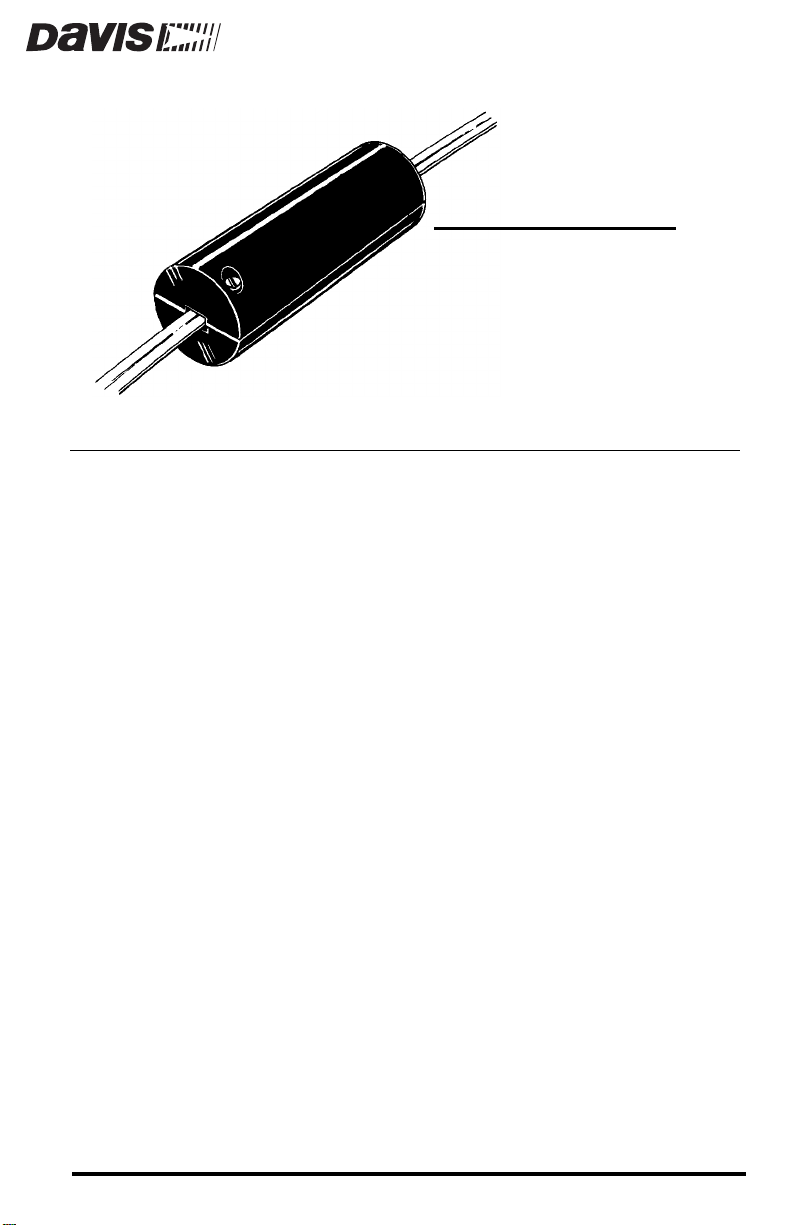
The Coupler Kit is used to connect standard extension cables to standard sensor cables. It includes both a 6-pin cable coupler and waterproof crimp-style
splice connectors for making the connection as well as a protective shell in
which you may place the connection point.
C
OMPONENTS
The Coupler Kit includes the following components. Please make sure you
have all listed components before continuing.
Protective Shell (in two pieces)
✦
✦
6-Pin Cable Coupler
✦
Four #4 x ∫” (12.5 mm) Screws
Seven Splice Connectors
✦
✦
One Cable Tie
TANDARD
ONDUCTOR CABLES
K
4-
IT
AND
T
OOLS AND MATERIALS NEEDED
You may need some of the following tools and materials in order to complete
your installation. Please be sure you have everything you need before beginning.
✦
Small Screwdriver
Pliers
✦
✦
Telephone Wire Stripper or Knife
✦
Hose Clamps or Conduit Clamps
Cable Clips or Weather-Resistant Cable Ties
✦
Product # 7957
IPS
ON
T
For the best connection, note the following suggestions:
T
O
C
ONNECT
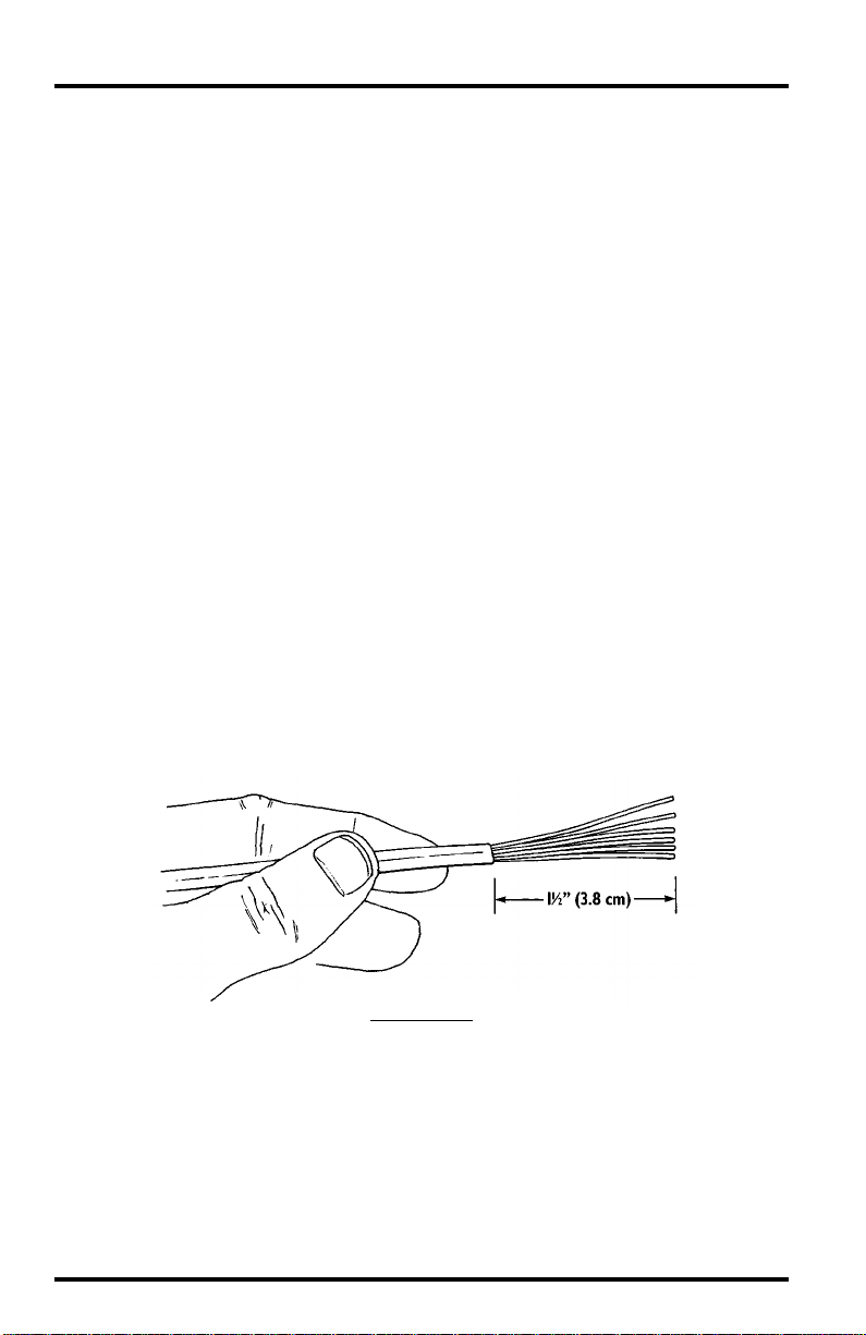
1. Cut the modular connector off the end of the cable.
2. Use a telephone wire stripper or a knife to strip away about 1 ∫ (3.8 cm) inches of the
AKING
M
✦
If the connection between the cables will be located outside, we recommend that
you use the splice connectors rather than the coupler.
With the splice connectors, there is less chance of the cables separating
and also less chance of water reaching the connection. Use the cable coupler only if the connection is located inside, protected from the effects of
weather and other stresses.
Try to place the connection between cables inside a building, underneath an eave,
✦
or in another location similarly shielded from rain.
✦
The protective shell must be well secured to avoid wind buffeting.
Use hose clamps for poles or conduit clamps for surface mount.
When securing cables, place a cable clip or tie on each side of the protective shell
✦
so the movement of the cables does not cause the connection to pull apart.
✦
It is a good practice to leave an extra length of cable near the connection point in
case future adjustments or repairs are necessary.
black shielding on the cable.
Do not strip away any of the colored shielding on the individual wires.
Repeat this procedure for the end of each cable you are connecting.
ONNECTIONS
C
THE
C
ABLES
U
SING
THE
S
PLICE
C
ONNECTORS
S
S
TRIP
HIELDING
Page 2 Coupler Kit
 Loading...