

Page 1
S
TANDARD AND
I
NDUSTRIAL
A
NEMOMETER
NSTALLATION MANUAL
I
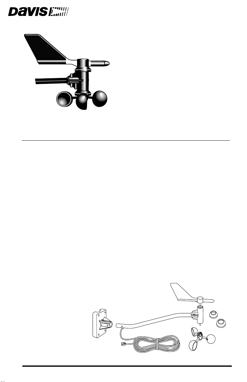
The anemometer enables you to measure and display wind-related conditions
such as wind speed, wind direction, wind run, wind chill, and the
temperature-humidity-sun-wind index.
Components
The anemometer includes the components listed below. Please be sure you
have all listed components before continuing. The installation hardware kit
contains the items most commonly needed for the installation of the anemometer. Which items you use from the kit depend on where you install your unit.
You may need to adapt or purchase additional hardware to fit your individual
requirements. Assess your installation and make sure you have all necessary
parts, tools, and materials before you begin.
Anemometer Arm with cable
✦
Anemometer Base
✦
✦
Wind Cups
Wind Vane
✦
Drip Rings
✦
Wind Vane
Anemometer Arm
with 40 feet (12.2 meters)
of cable
Drip
Rings
Anemometer
Base
Wind Cups
Product # 7911, 7914
Page 2
1.
Tools and Materials Needed
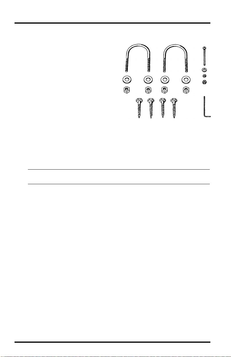
✦
Installation Hardware Kit
✦
Two U-Bolts
✦
Four 1/4” Flat Washers
✦
Four 1/4” Hex Nuts
Four 1/4” x 1 1/2” Lag
✦
Screws
One #4-40 x 1 1/4” Pan
✦
Head Screw
✦
One #4 Flat Washer
✦
One #9 Lock Washer
✦
One #4-40 Hex Nut
Allen Wrench
✦
Tools and Materials Needed
You will need the following tools and materials to install your anemometer:
✦
Cable Clips or Weather-Resistant Cable Ties
Note: Make sure the clips or ties you use to secure the anemometer cable have screw holes or other means
for mounting the cable. Do not use metal staples to secure the cables.
✦
Stainless Steel Hose Clamps
Small Screwdrivers
✦
✦
Adjustable Wrench
✦
Hand-Held Compass or Local Area Map
Testing the Anemometer
Before beginning your installation, follow the instructions below to test the anemometer wind speed and wind direction functions.
Connect the anemometer cable to the appropriate connector on your sensor
interface module (SIM) or junction box.
2.
Push the wind cups onto the smaller of the two stainless steel shafts at the
end of the arm.
3.
Spin the wind cups
them too hard you may knock them off.
4.
Check the display on your weather station to make sure you are getting a
wind speed reading.
5.
Grab the larger of the two stainless steel shafts at the end of the arm with
your fingers and twist the shaft about 1/2 turn.
gently
. You haven’t secured them yet, and if you spin
Page 2 Standard and Industrial Anemometer
Page 3
6.
7.
1.
2.
3.
Assembling the Anemometer
Check the display to make sure the wind direction reading on your display
changes.
Note: The wind direction readings will not change as rapidly as you turn the shaft. The station uses a low
pass filter to smooth out the constant small shifts in wind direction and keep the direction display
from jumping about in gusty winds.
Disconnect the cables when you are finished testing the anemometer.
Assembling the Anemometer
Attach the drip rings and the wind cups to the anemometer and check the
mounting base orientation before you install it. The wind vane is attached after
the anemometer has been installed.
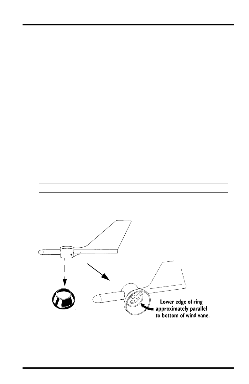
Attaching the Drip Rings
The anemometer drip rings provide protection against icing of the wind vane
and wind cups. Follow the instructions below to attach the two drip rings.
Place one of the drip rings on a flat surface with the small hole facing up.
Securely press the wind vane on top of the drip ring.
Note: You may want to start with the vane tilted slightly.
Make sure the ring fits securely between the two ridges on the vane with the
lower edge parallel to the bottom of the wind vane.
Installing the drip ring onto the wind vane
Page 3
Page 4
Assembling the Anemometer
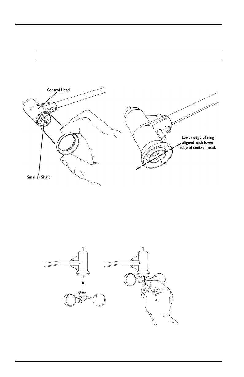
Install the small end of the other drip ring on the wind cup end of the anemometer control head as shown below.
Note: The wind cup end of the control head has the smaller of the two stainless steel shafts.
Gently push up the drip ring until it reaches the groove on the control head.
Make sure the lower edge of the drip ring is aligned with the lower edge of
the control head.
4.
5.
6.
1.
2.
Installing the drip ring onto the anemometer control head
Attaching the Wind Cups
Before installing the anemometer, attach the wind cups. Wait until you have
installed the anemometer before you attach the wind vane.
Push the wind cups onto the smaller of the two stainless steel shafts at the
end of the arm.
Push cups onto
stainless steel
shaft
Attaching wind cups to the anemometer
Slide the wind cups as far up the shaft as possible.
Page 4 Standard and Industrial Anemometer
Tighten set screw
with allen wrench
Page 5

3.
4.
5.
1.
2.
3.
4.
Choosing the Best Anemometer Location
Use the allen wrench provided to tighten the set screw on the side of the
wind cups.
Note: When you let go of the wind cups, they should drop slightly.
Spin the wind cups. If they do not spin freely, loosen the set screw, lower the
cups slightly, then retighten the set screw.
Repeat Step 4 until the wind cups spin freely.
Checking the Anemometer Base Orientation
You will need to know which way to orient the base before installing it.
Insert the anemometer arm into the base
Attempt to push the #4-40 x 1 1/4” pan head screw through the holes in the
arm and the base as described in “Attaching the Wind Vane” on page 8.
If the screw does not slide easily through the holes, rotate the base 180˚ to
line up the opposite holes, then try again.
Note the correct base orientation for use when you install the base later in
the installation process.
Choosing the Best Anemometer Location
Use the following guidelines to determine the best location for your anemometer.
✦
Make sure you install the anemometer in a location where wind flow is
unobstructed by trees and nearby buildings.
For the most accurate readings, the anemometer should be mounted at
✦
least 4 feet (1.2 m) above the roof line.
You may do this by mounting the anemometer on a television antenna
mast, a wooden post, or a metal pipe.
Make sure the antenna mast or metal pipe is properly grounded. You may
✦
want to use Davis’ Grounding Kit.
✦
If you are not certain about how to ground your installation, consult a
qualified professional for national and local codes.
Note: If you live in an area subject to frequent thunderstorms, installing a lightning rod nearby can reduce the
risk of damage.
Page 5
Page 6

1.
2.
3.
1.
2.
Installing the Anemometer
Installing the Anemometer
Use the following procedures to mount the anemometer.
Installing on a Sensor Mounting Arm
Consult the Sensor Mounting Arm manual for instructions. You will need to
return to this instruction manual after installing onto the Sensor Mounting Arm
for instructions on attaching the wind vane (see “Attaching the Wind Vane” on
page 8).
Installing the Base on a Wooden Post or Surface
Hold the anemometer base against the
wood surface and use a pencil to mark the
location of the four holes on the base.
Use a drill with a 3/16” (5-mm) drill bit to
make pilot holes in these locations.
Drive the lag screws through the holes in
the anemometer base and into the wood.
Attaching base to wooden post
Installing the Base on an Antenna Mast or Metal Pipe: Outside
Diameter 7/8” to 1 1/4” (22 to 32 mm)
Hold the anemometer base against the pipe and
insert the two U-bolts through the back of the
base so that the U-bolts wrap around the pipe.
Place a 1/4” washer and a 1/4-20 hex nut over
each end of the U-bolts and use a wrench to
tighten the hex nuts.
Attaching base to a pipe
using U-bolts
Page 6 Standard and Industrial Anemometer
Page 7

1.
2.
1.
2.
Installing the Anemometer
Installing the Base on a Metal Mast or Pipe: Outside Diameter
Greater than 11/4 inch (32 mm)
Use stainless steel hose clamps to attach the mounting base to masts or pipes
larger than 1 1/4” diameter.
Use two stainless steel hose clamps large enough
to fit around the mast or pipe and the anemometer
base.
You may purchase hose clamps at your local hardware store.
Hold the anemometer base against the pipe and
fasten the hose clamps over the anemometer base
and around the metal mast or pipe.
Attaching base to a pipe
using hose clamps
Attaching the Anemometer Arm to the Base
Insert the anemometer
arm into the anemometer
base.
Guide the anemometer
cable through the slot as
you insert the arm.
Insert the pan head screw
into one of the holes in the
base and slide it through
the arm.
Inserting arm into base
3.
Secure the pan head
screw using the flat washer,
lock washer, and hex nut as
shown.
Attaching the anemometer arm to the base
Page 7
Page 8

Installing the Anemometer
Attaching the Wind Vane
To mount the wind vane, you will need to look at the console display in order to
orient the vane accurately. You may wish to have a friend or family member on
the ground do this for you. Or, you may wish to bring the console and SIM/junction box onto the roof with you.
1.
Connect the anemometer cable to the
SIM/junction box.
2.
Press WIND key on console if
necessary to display wind direction in
degrees.
3.
Use the compass or map to determine
270° W90° E
in which direction (N, S, E, W,) the
anemometer arm is pointing.
4.
Use the wind direction chart to find
the degree reading which corresponds
to that direction.
5.
Slowly turn the wind direction shaft
Wind direction chart
with your fingers. Stop turning when the weather station display reaches
the degree reading obtained in step 4.
Because of the low pass filter used by the station (see “Testing the Anemometer” on page 2), the wind direction reading requires approximately 5 seconds to stabilize each time you turn the shaft. You will need to turn the
shaft, wait, and turn it again until you eventually “zero in” on the desired
wind direction reading.
6.
Being careful to keep the stainless steel shaft from turning, place the wind
vane on the shaft with the bullet-shaped nose of the vane pointing in the
same direction as the arm.
0° N
180° S
45° NE315° NW
135° SE225° SW
Push the
wind vane
onto the
stainless steel
shaft
Installing the wind vane
Tighten set screw
with allen wrench
Page 8 Standard and Industrial Anemometer
Page 9

Slide the wind vane down onto the shaft as far as it will go.
Use the allen wrench provided to tighten the set screw on the side of the
wind vane.
Test your assembly by pointing the wind vane in any direction and (using
the compass or map as a guide) making sure the console displays the correct
wind direction. Readjust the vane if necessary.
Because of the low pass filter used by the station (see “Testing the Anemometer” on page 2), you need to allow the wind direction reading approximately 5 seconds to stabilize after you turn the vane.
10. Spin the wind cups to make sure you get a wind speed reading. Readjust the
cups if necessary.
11.
Secure the cable to the metal mast or pipe with electrical tape. Secure the rest
of the cable according to the directions below.
Securing the Cable
To prevent fraying or cutting of the anemometer cable where it is exposed to
weather, it is very important that you secure it so it doesn’t whip about in the
wind. Use cable clips or weather resistant cable ties to secure the cable. Place
clips or ties approximately every 3 to 5 feet (1 to 1.6 m).
Maintenance
7.
8.
9.
Securing cable (standard cable shown)
Note:
Do not use metal staples or a staple gun to secure cables. Metal staples—especially when installed
with a staple gun—have a tendency to cut the cables.
Maintenance
Your anemometer does not require any regular maintenance.
CAUTION:
DO NOT attempt to lubricate the wind cup shaft and bearings or the wind vane shaft. Natural or
synthetic lubricants will inhibit the normal operation of the anemometer.
Page 9
Page 10

Troubleshooting
Troubleshooting
While your anemometer is designed to provide years of trouble-free operation,
occasionally problems may arise. If you are having a problem with your unit,
please check the following troubleshooting procedures before sending the unit in
for repair . You will be able to solve many of the pr oblems yourself. If, after checking these procedures you are unable to solve the problem, please call Davis Technical Support for further instructions (see “Contacting Davis Instruments
T echnical Support” on page 11.) Please do
receiving prior authorization from Davis Technical Support.
Wind speed reads 0 all the time or intermittently
• Make sure anemometer cable is plugged into the jack marked WIND on the
junction box.
• Check for broken wire along length of anemometer cable. Carefully check
areas where the cable has been secured.
• Try dropping the wind cups approximately 1/16” to 1/8” (1.5 to 3 mm) lower
on the mounting shaft. Use the included Allen wrench to loosen and retighten
the wind cup assembly.
• If you still do not get a reading, the problem is probably with the anemometer.
Contact Davis Technical Support for return authorization.
not
return your unit for repair without
Wind speed reading seems too high or too low
• Check installation by spinning wind cups. If the wind cups spin freely and
your weather station displays a wind speed then the wind cups are installed
correctly. If the wind cups don’t spin freely, then try dropping the wind cups
approximately 1/16” to 1/8” (1.5 to 3 mm).
• Check calibration number and adjust if necessary.
• Check for any obstructions blocking the wind near the anemometer.
Wind direction reading is dashed out
• Make sure anemometer cable is plugged into the jack marked WIND on the
junction box.
• Check for broken wire along length of anemometer cable. Carefully check the
places where the cable has been secured.
Note:
If these steps do not solve the problem, the problem is probably with the anemometer. Call Davis Technical Support for return authorization.
Page 10 Standard and Industrial Anemometer
Page 11

Contacting Davis Instruments Technical Support
If you have any questions about our products, please call Davis Technical Support. We’ll be glad to help. Most questions can be answered while you’re on the
phone. You can also email us for support, or visit our website. Sorry, we are
unable to accept collect calls.
Voice Line: 510-732-7814, Monday - Friday, 7:00 am - 5:30 pm, PST
Fax: Line 510-670-0589
Email: support@davisnet.com
World Wide Web: www.davisnet.com
Specifications
Wind Direction
Display Resolution: 16 points (22.5˚) on compass rose, 1˚ in digital display
Accuracy: ± 7˚
Wind Speed
Range: 2 to 175 mph., 4 to 280 kph, 2 to 152 knots, 0.9 to 78 m/2s
Accuracy: ± 5%
Specifications
Page 11
Page 12

Product Numbers: 7911 & 7914
Davis Instruments Part Number: 7395-032
Anemometer, Standard & Industrial
Rev. B Manual (3/14/2001)
This product complies with the essential protection requirements of the EC EMC
Directive 89/336/EC.
© Davis Instruments Corp. 2001. All rights reserved.
3465 Diablo Avenue, Hayward, CA 94545-2778
510-732-9229 • Fax: 510-732-9188
E-mail: info@davisnet.com • www.davisnet.com
 Loading...