

Davis 7860 Installation Manual
TANDARD
S
XTERNAL TEMPERATURE
E
UMIDITY SENSOR
H
NSTALLATION MANUAL
I
The External Temperature/Humidity Sensor (T/H Sensor), may be used with
the Weather Monitor II®, GroWeather®, Energy EnviroMonitor®, and the
Health EnviroMonitor®. The T/H Sensor enables you to display temperature
and humidity-related conditions. For a complete list of the conditions you may
display using the T/H Sensor, consult your station manual.
NDUSTRIAL
& I
Components
The T/H Sensor includes the following components. Please make sure you
have all listed components before continuing.
Temperature/Humidity Sensor with cable
✦
The standard version comes with a 40’ (12 m) cable. The industrial version comes with a 16’ (5 m) shielded cable.
Five #4 x 1/2" pan headself-threading screws
✦
✦
One #4 Flat Washer
✦
One Cable Clamp
/
Tools and Materials Needed
In addition to the components listed above, you will need the following tools
and materials. Please be sure you have everything you need before beginning
the installation.
Small Phillips-head screwdriver
✦
Drill and 1/16” to 3/32” (#43, 2 mm) drill bit.
✦
✦
Cable clips or weather-resistant cable ties with screw holes or other
means for mounting. Do not use staples.
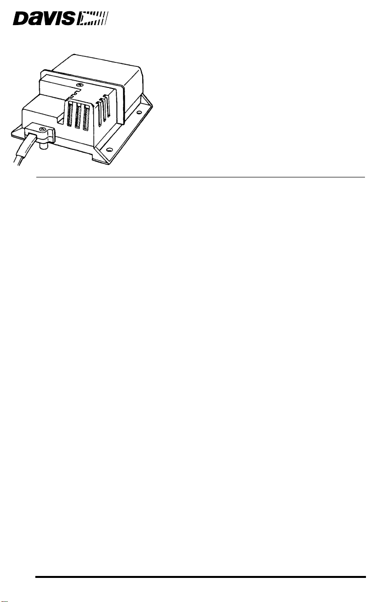
Product # 7859 & 7860
1.
Testing the T/H Sensor
Be sure to test the sensor before installing it.
Attach the sensor cable to the appropriate connector on the junction box/
sensor interface module (SIM). Refer to the T/H Sensor installation information shown below and on the following pages.
2.
Press the appropriate key on your console as necessary to make sure you
are getting an outside air temperature reading on the console.
3.
Press the appropriate key on your console as necessary to make sure you
are getting an outside humidity reading on the console.
Installing the T/H Sensor
Follow the instructions in this section to install your sensor. Make sure you
read “Choosing a Location for the T/H Sensor” on page 4 as it contains important information concerning placement of the sensor.
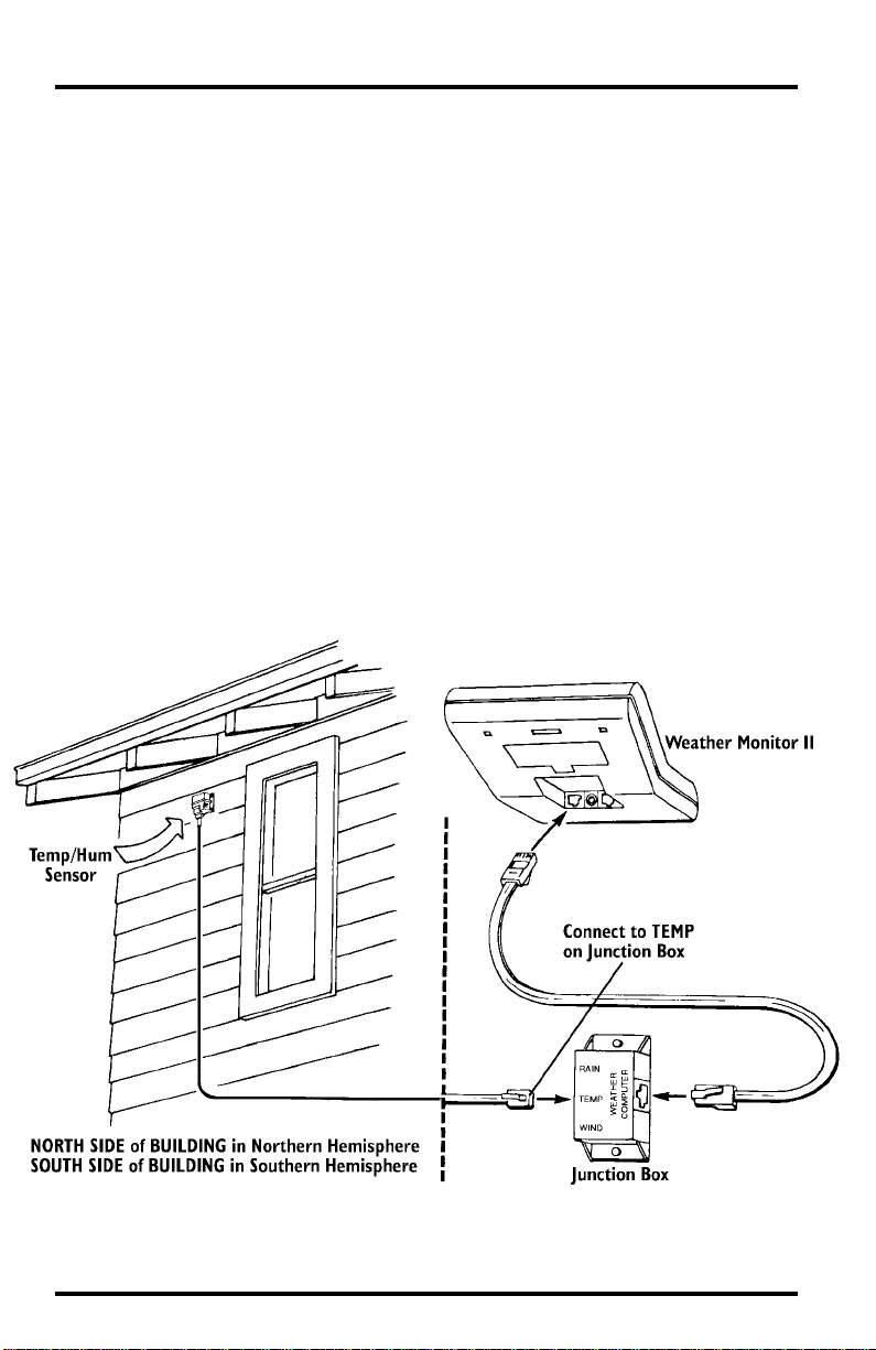
Typical Weather Monitor II Installation
The illustration below shows a typical T/H Sensor installation for the Weather
Monitor II.
Typical Weather Monitor II installation
Page 2 Standard & Industrial External Temperature/Humidity Sensor
Note: You may also use the Radiation Shield and Sensor Mounting Arm (pictured below) if desired.
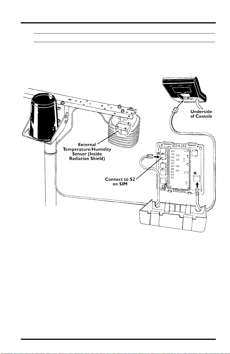
Typical Standard GroWeather/EnviroMonitor Installation
The illustration below shows a typical Standard T/H Sensor installation for the
GroWeather, Energy EnviroMonitor, or the Health EnviroMonitor.
Typical standard GroWeather/EnviroMonitor installation
Installing the T/H Sensor Page 3
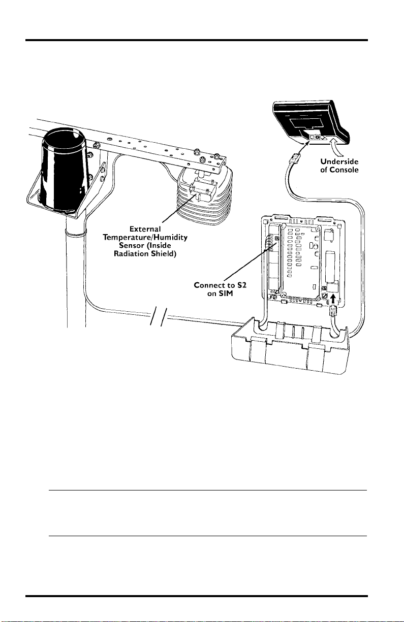
Typical Industrial GroWeather/EnviroMonitor Installation
The illustration below shows a typical Industrial T/H Sensor installation for
the GroWeather, Energy EnviroMonitor, or the Health EnviroMonitor.
Typical industrial GroWeather/EnviroMonitor installation
Choosing a Location for the T/H Sensor
Use the following suggestions to find a suitable location in which to mount the
sensor . Care taken in choosing a location impr oves the accuracy, reliability, and
durability of the sensor. The ideal location would be on the North side of the
building in the Northern Hemisphere, or the South side in the Southern Hemisphere.
Note: When you choose a location for the sensor, always take into consideration nearby objects. Objects
which heat up in direct sunlight such as pavement, or that produce radiative cooling effects such as a
fountain, may affect the temperature of the air in the vicinity which can affect the temperature and
relative humidity readings from the sensor.
Page 4 Standard & Industrial External Temperature/Humidity Sensor
 Loading...