

Davis 7817 Installation Manual
External Temperature Sensor Temperature Probe
Installation Manual
The external temperature sensor may be used with the
Weather Monitor II, Weather Wizard III, Weather Wizard II
(S), GroWeather or EnviroMonitor Davis weather stations.
The sensor may be used to measure outside temperature,
though you may bury the sensor or immerse it in water to
measure soil or water temperature instead of air
temperature. The standard version of the sensor comes with a 40' (12 m) cable
Tools and Materials Needed
You may need some of the following tools and materials to complete your
in
stallation. Please be sure you have everything you need before beginning.
• Shovel or spade to dig hole for sensor if using as a soil temp sensor
• Metal or plastic conduit to protect
cable from rodents
• Cable clips or weather-resistant cable ties with screw holes or other means for
mounting to secure cable
Testing the Sensor
Test the sensor before installing it.
1. Attach the sensor cable to the appropriate connector on the junction box/
sensor interface
manual for more information.
2. Press the appropriate key on your console as necessary to make sure you are
getting an outside temperature reading on the console.
Choosing a Location for the Sensor
Use the suggestions below to find a suitable location in which to mount the
. Care taken in choosing a location improves the accuracy, reliability, and
sensor
durability of the sensor. The ideal location would be on the NORTH SIDE of the
building (south side in the Southern Hemisphere).
module (SIM). Consult your station manual or installation
.
Note: When choosing a location for the sensor you should take into consideration the objects
nearby. Objects which heat up in direct sunlight or produce radiative cooling effects may
affect temperature readings by changing the surrounding air temperature.
Look for a location which satisfies the following requirements (Davis’ Radiation
Shield provides additional protection for the sensor):
• Place the sensor in a location where it will not be in direct sunlight and whe
it will have limited exposure to reflected sunlight.
• Limit the exposure of the sensor to the open night sky.
• Place the sensor at least 5 feet from man-made s
ources of heat.
• Keep the sensor away from AC power lines.
re
1
Testing the Sensor
• If possible, place the sensor at least 5 feet from any surface which is
exposed to direct sunlight because the heat from this surface may affect air
temperature readings in the vicinity.
• Place the sensor in a location at least 10 feet away from lights or lamps.
• If you are unsure about a location's exposure to the night sky, check for dew
at that location on a light dewy morning. If the area is dry, the location
should work well.
• Keep the sensor and most of the cable at least 10 feet
from 110 Vac, 60Hz
utility power. Do not run the sensor cable parallel to house wiring. Mount
the sensor at least 30 feet from high-voltage power lines and transformers.
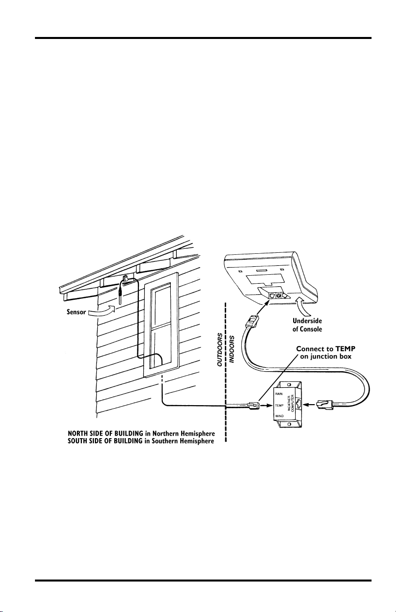
Typical Weather Wizard II (S), W
eather Wizard III, or Weather
Monitor II Installation
The illustration below shows a typical installation for the Weather
Wizard II (S), Weather Wizard II
I, or Weather Monitor II.
Typical Installation
Typical Standard GroWeather/EnviroMonitor Installation
The illustration on the next page shows a typical installation for the
GroW
eather (used to measure air temperature), Energy EnviroMonitor, or the
Health EnviroMonitor. The sensor cable attaches to connector S2 on the sensor
interface module (SIM). On GroWeather systems, the sensor can also attach to
connector S3 to measure a second temperature (such
2
as soil temperature).
 Loading...