

Davis 7774 Installation Manual
ERMINAL
T
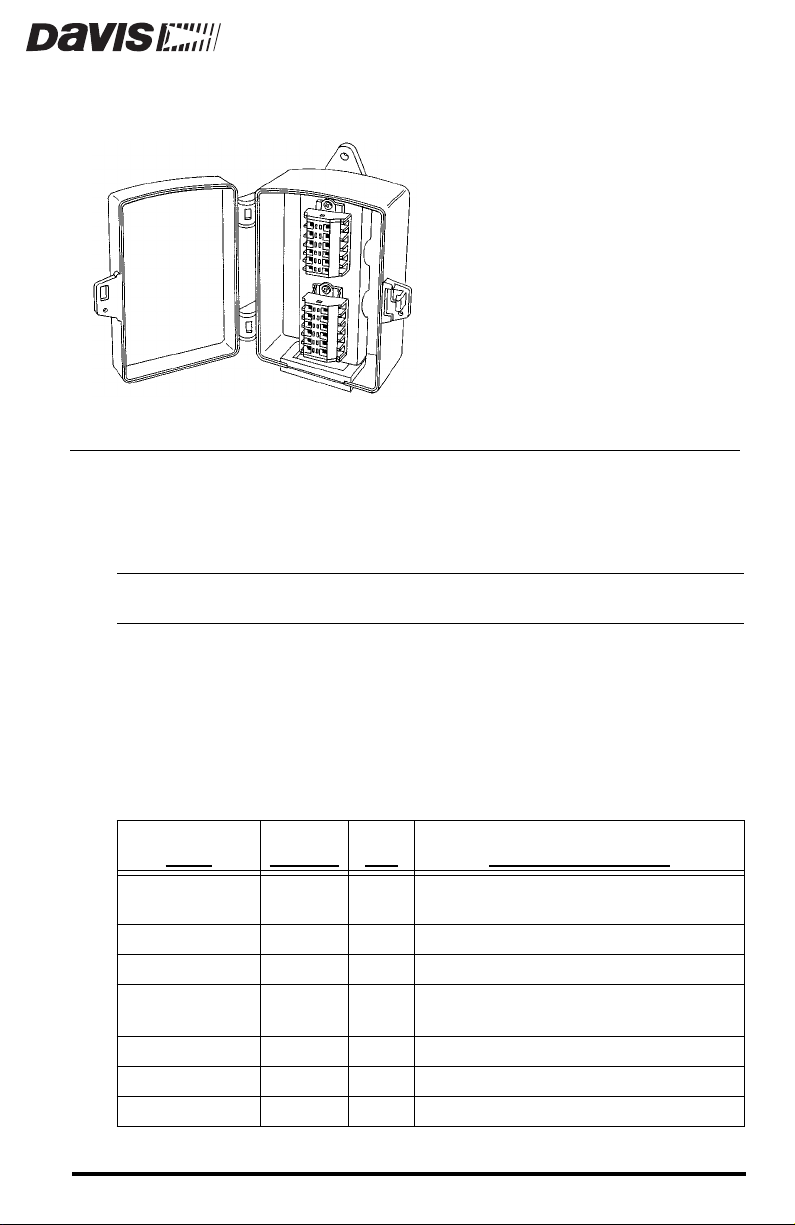
The Terminal Box provides easy, reliable connections for splicing wires and
cables. All connections are housed in a weather-resistant enclosure. The terminal box can simplify and speed up the task of wiring the weather station sensors, sensor interface module (SIM), and communication lines.
Note:
The terminal blocks in the Terminal Box are rated for 300V, 10A and are intended for 26-16 AWG
(.08-1.5 mm) wire. When wiring, all applicable building and electrical codes must be followed.
When connecting shielded cables to shielded cables, connect each colored wire
to the same colored wire on the extension cable (or other cable). In twisted-pair
cables, all black wires are ground and may be shorted together.
When connecting standard cables to standard cables, you may also connect
each colored wire to the same colored wire on the extension cable (or other
cable). In some cases, however, wires may be combined in order to use fewer
terminals on the terminal block. Consult the table below:
B
OX
W
W
IRES IN
S
ENSOR
Rain Collector 4 2 Twist RED and BLACK as one wire and GREEN and YELLOW as
Temp/Hum Sensor 6 5 Twist RED and BLACK as one wire (ground).
Temp Sensor 4 2 Twist RED and BLACK as one wire (ground). Ignore GREEN.
UV/Leaf Wetness Sensor 6 3 Twist RED and BLACK as one wire (ground). Ignore GREEN and
Solar Radiation Sensor 4 3 Twist RED and GREEN as one wire (ground).
Anemometer 4 4
SIM/Junction Box Cable 8 8
STD. C
ABLE
IRES
U
SED
another wire.
BLUE.
N
OTES FOR STANDARD CABLES
Product # 7774

OMPONENTS
C
The Terminal Box includes the following components. Please make sure you
have all listed components before continuing.
Terminal Box with Terminal Blocks
✦
Two #8 x Ω” (19 mm) Self-Threading Screws
✦
OOLS
T
AND
You may need some of the following tools and materials in order to install the
terminal box.
Medium Slotted Screwdriver
✦
✦
Small Slotted Screwdriver
Drill with #29 (.136”, 3.5 mm) Drill Bit
✦
Center Punch
✦
ATERIALS
M
N
EEDED
Page 2 Terminal Box
OUNTING
M
THE
ERMINAL
T
B
OX
Y ou may mount the Terminal Box against a wall or other vertical surface or you
may simply lay it down on a horizontal surface. The preferred mounting
method is to mount it on a vertical surface in a protected location with the rubber grommet facing down.
Note: You may install the wires through the grommet and into the terminal blocks before or after mounting
the Terminal Box.
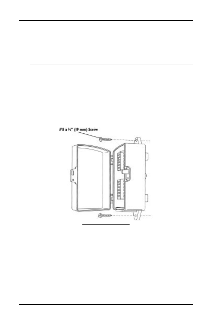
1. Hold the Terminal Box against the mounting surface and mark the location of the two
screw holes.
Use a pencil or a center punch to mark the location of the screw holes.
2. Drill pilot holes in the marked locations using a drill with a #29 (.136”, 3.5 mm) drill
bit.
3. Secure the Terminal Box to the mounting surface using the #8 x Ω ” (19 mm) screws
as shown below.
M
OUNTING
THE
T
ERMINAL
B
OX
Mounting the Terminal Box Page 3
 Loading...