

Davis 7745 Installation Manual
Daytime Fan-Aspirated
Radiation Shield Kit
Installation Manual
for Vantage Pro & Vantage Pro Plus Stations
Introduction
These instructions describe how to upgrade a non-aspirated Vantage Pro radiation shield
to a Daytime Fan-Aspirated Radiation Shield. The upgrade kit can be installed on any
Vantage Pro® or Vantage Pro Plus Integrated Sensor Suite (ISS) equipped with a
round-plate non-aspirated, radiation shield. The round-plate non-aspirated radiation
shield replaced the previous square-plate shield at the beginning of 2003.
Note: The Daytime Fan-Aspirated Radiation Shield Kit can only be installed on round-plate non-aspirated
radiation shields.
Components
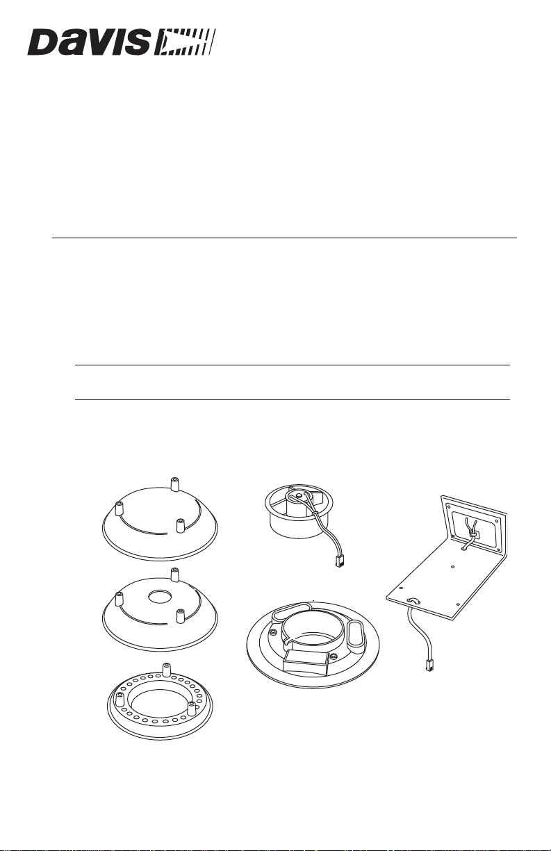
The upgrade kit includes the items shown in “Figure 1” and “Figure 2”.
Closed Cap Plate
Open Cap Plate
Open Plate
Fan Unit
Solar Panel &
Mounting Bracket
Fan Plate
Figure 1. Daytime Fan Kit Components
Product # 7745
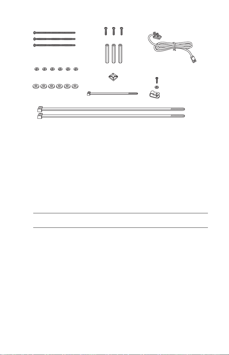
#8-32 x 1/2" Screws (3)
#8-32 x 3-1/4"
Screws (3)
Threaded Spacers (3)
#8 Split-Lock Washers (6)
Cable Tie Mount
#8 Flat Washers (6)
4" Cable Tie
12" Cable Ties (2)
Figure 2. Daytime Fan Kit Hardware
Power Cable
Assembly
#4 x 3/8" Screw
#4 Flat Washer
Cable Clamp
Tools Needed
You may need some or all of the following tools and other items to complete the
upgrade:
• A medium Phillips-Head screwdriver
• A medium slot-tip screwdriver
Cabled ISS Only: Wire cutters
•
• Other tools as required to remove and re-mount the ISS
Wireless ISS Only: CR-123A 3-volt lithium battery (optional)
•
Note: If you are upgrading an ISS that has been in service for a year or more, you should consider
changing the ISS battery during the upgrade.
Installation Overview
Installing the Daytime Fan Kit is not very complicated and should take only 30 to 60
minutes to complete.
These are the steps to install the Daytime Fan components:
1. Put the console into Setup Mode.
2. Take the ISS down from its installed position.
3. Disassemble the standard radiation shield.
4. Remove the solar panel if you have a Wireless ISS.
5. Assemble the lower section of the fan-aspirated shield.
6. Install the fan unit.
7. Assemble the upper section of the fan-aspirated shield.
8. Re-Install the ISS.
9. Take the console out of Setup Mode.
2
Installing the Daytime Fan Kit
)
Put Console in Setup Mode
1. At your Vantage Pro console, press and hold the DONE key and then press the -
key to put the console in Setup Mode. This prevents the recepti on of erroneous data
from the rain collector while you are removing the ISS.
Note: If the console acquires erroneous data during the upgrade, refer to “Take the Console Out of Setup
Mode” on page14 for instructions on clearing data. Additional information on clearing and setting
console data can be found in the “Vantage Pro Console Manual.”
Take Down the ISS
CAUTION: Please work on your Vantage Pro ISS in a safe place. We strongly recommend tha t you take
down the ISS before beginning the upgrade.
If you are installing the Daytime Fan Kit on an ISS that has already been placed into
service, you will need to take down the ISS and move it to a convenient and safe place to
perform the installation.
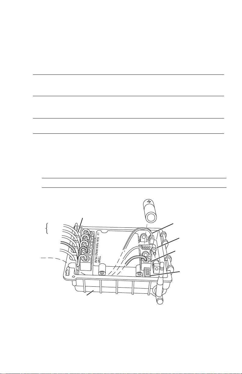
1. At the ISS, open the Sensor Interface Module (SIM) housing cover and disconnect
the WIND (anemometer) cable.
Note: The SIM housing is located on the bottom of the radiation shield.
3-Volt Lithium Battery
(Wireless ISS Only)
Solar Panel Power
(Wireless ISS Only)
AC Power
(optional)
Console Cable
(Cabled ISS Only)
Optional
TEMP HUM
Cable Routing Channels
(press cables fully into channel)
UV
SUN
RAIN
WIND
DIP Switches
(Wireless ISS Only
SIM Housing
Figure 3. SIM Connections
2. Cabled ISS Only:
3. You can now remove the ISS from its mounted position. Move it to a safe place to
install the kit components.
Disconnect the console cable from the SIM.
3
Disassemble the Standard Radiation Shield
Note: We recommend using a workbench or table to perform the following procedures.
Turn the ISS upside down with the rain collector cone
1.
on the bottom.
2. Disconnect the RAIN cable and, if present, disconnect
the SUN and UV cables from the SIM.
3. Wireless ISS Only: Disconnect the solar power
cable.
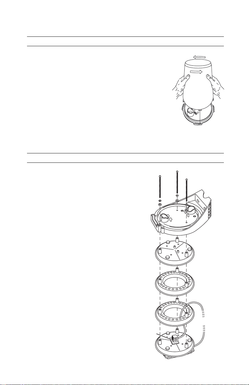
4. Turn the ISS right-side up with the cone on top.
5. Remove the rain collector cone from the ISS base by
rotating the cone counter-clockwise. When the cone’s
latches line up with openings in the base, you can lift
the cone off. The cone fits in the base tightly and may
require extra pressure to remove the first few times.
See Figure 4.
Tip: Steady the ISS base between your knees when removing the cone.
6.
Remove the three 8-32 x 4”
screws holding the radiation
shield plates together. Save
these three screws for use in the
next procedure, “Assembling
the Lower Shield.”
#8-32 x 4" Screw
#8 Lock Washer
#8 Flat Washer
Twist to Open
Figure 4. Remove Rain
Collector Cone
4
Figure 5. Standard Radiation
Shield Assembly Diagram
ISS Base
Top Plate with
Insulating Disk
Radiation Shield
Open Plates
Temp/Hum
Sensor
Bottom Plate with
SIM Housing
Temp/Hum
Cable
7. Route the RAIN cable behind the drain and out the hole near the drain.
ISS Base
Rain Collector
Tipping Bucket
Drain
RAIN Cable
Install Cable
Figure 6. Route RAIN
Cable Around Drain and
Tie Mount
Here
Route Cable Here
through Hole
8. Place the adhesive-backed cable tie mount next to
the hole near the drain, and secure the cable with
the small cable tie.
Figure 7. Secure the RAIN Cable
Cable Tie
Mount
Cable Tie
RAIN Cable
Route Cable
Through Hole
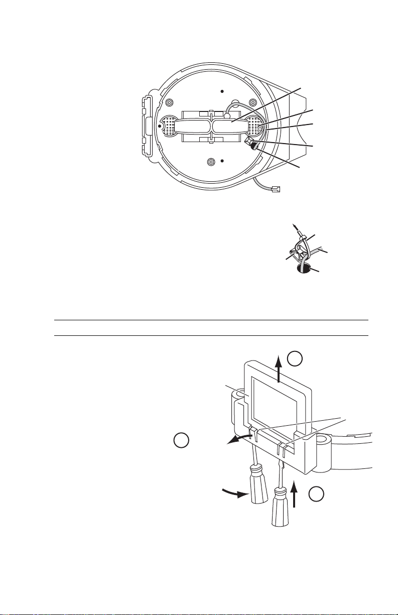
Wireless ISS Only: Remove the Solar Panel
Note: A new solar panel included with the kit replaces the original solar panel.
Insert a slot-tip screw-
1.
driver between the solar
panel retaining tabs and
the solar panel.
See Figure 8. .
2. Pry the retaining tabs out
just enough to free the
solar panel.
3. Lift the solar panel
straight up to remove it
from the ISS base.
3
Lift solar panel to remove.
Solar Panel
Solar Panel
Retaining Tabs
2
Pry tab out to
release solar panel.
1
Insert screwdriver
between tab and
solar panel.
Figure 8. Remove the Solar Panel
5
 Loading...