

Davis 7728 Installation Manual
ULTI-PURPOSE
M
HELTER
S
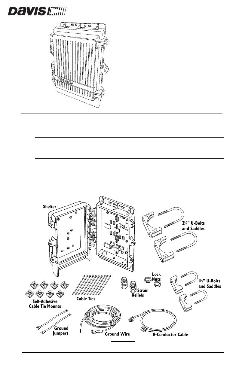
The weather-resistant Multi-Purpose Shelter (MPS) may be used to protect a
number of system components from the elements.
CAUTION:
OMPONENTS
C
The MPS includes the following components. Please make sure that you have
all the listed components before continuing.
Please note that we have made every attempt to design and manufacture a safe product,
but Davis Instruments assumes no liability for any injury or damage caused directly or indirectly by the installation or use of this product.
C
OMPONENTS
Product #7728
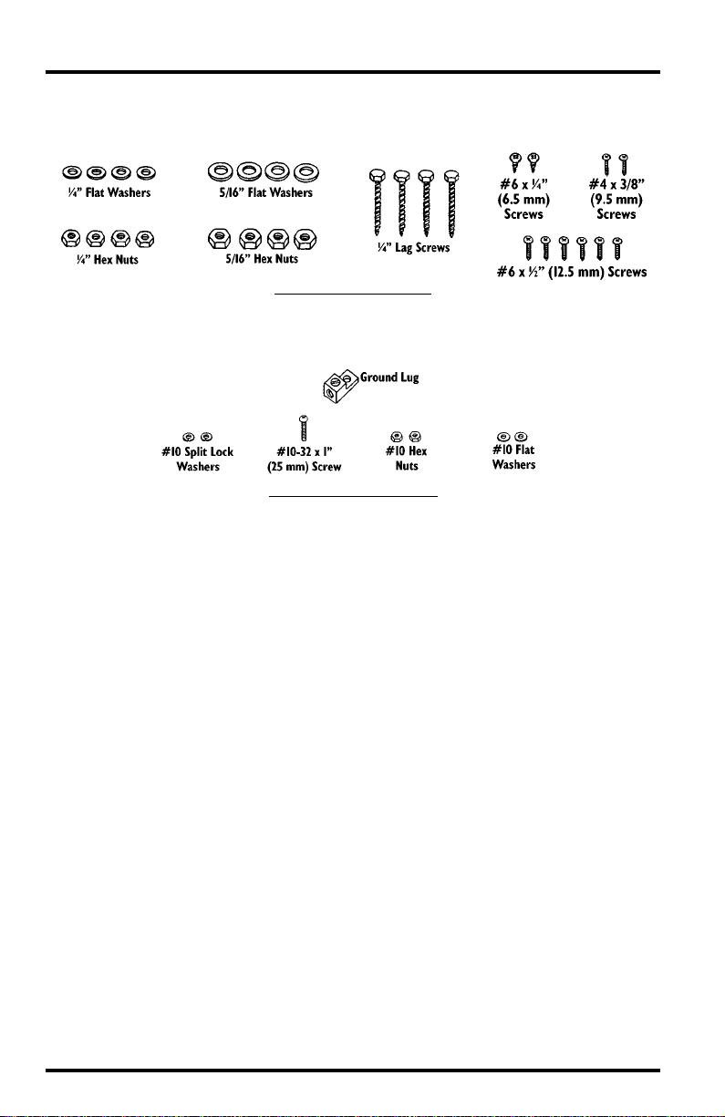
The hardware kit included with the MPS includes the following components.
Please make sure that you have all the components before continuing.
H
ARDWARE KIT COMPONENTS
The ground lug kit included with the shelter includes the following components. Please make sure that you have all the components before continuing.
G
ROUND LUG KIT COMPONENTS
T
OOLS AND MATERIALS NEEDED FOR
I
NSTALLATION
You may need some of the following tools and materials in order to install the
shelter.
System Components
✦
You will need the various system components you plan to install inside
the shelter. Some sample installation configurations are shown in “Sample MPS Configurations” on page 3.
Medium Flat Head Screwdriver
✦
✦
Medium Phillips Head Screwdriver
Wrench or 3/8" Nut Driver
✦
Large Adjustable Wrench (1 3/8" Opening)
✦
✦
Wire Cutter
Wire Stripper or Knife
✦
Pliers
✦
✦
Electrical Tape and/or Silicone Caulking
Double-Sided Tape
✦
Page 2 Multi-Purpose Shelter
TTACHING
A
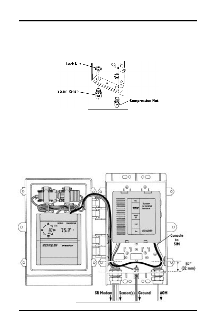
Attach both strain reliefs to the MPS as shown below. You will need to install
the strain reliefs before running cables into the MPS. Secure the strain r eliefs by
tightening the lock nuts. Do not tighten the compression nuts until you have
completed your installation (see “Securing the Cables” on page 12).
AMPLE
S
Console, Sensor Interface Module (SIM), and Short-Range (SR) Modem
MPS C
The illustrations below show three sample MPS installations. Consult the
installation manuals supplied with system components for wiring instructions.
The illustration below shows an MPS installation which includes the console,
SIM, and SR Modem. When installing, make sure the indicated cable tie
mounts are attached to the MPS so the centers of the mounts are 1-1/4" (32
mm) from the bottom of the shelter.
C
ABLE
TRAIN
S
ONFIGURATIONS
I
NSTALLING
ELIEFS
R
S
TRAIN
R
ELIEFS
C
, SIM, SR M
ONSOLE
Attaching Cable Strain Reliefs Page 3
ODEM
I
NSTALLATION
Console, Sensor Interface Module (SIM), and Link isolator
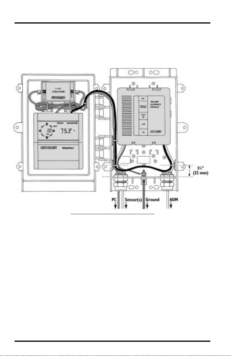
The illustration below shows an MPS installation which includes the console,
SIM, and Link Isolator. Make sure the indicated cable tie mounts are attached
to the MPS so the centers of the mounts are 1-1/4" (32 mm) from the bottom of
the shelter.
C
ONSOLE
, SIM,
AND
L
I
SOLATOR
, I
NSTALLATION
INK
Page 4 Multi-Purpose Shelter
 Loading...