

Page 1
OMPLETE
C
YSTEM SHELTER
S
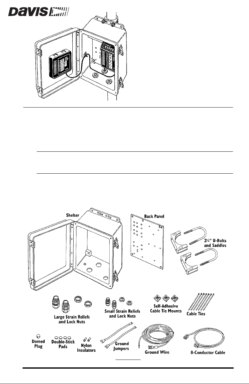
The weather-resistant Complete System Shelter (CSS) provides protection fr om
the elements for system components such as the console, Solar Power Kit components, sensor interface module, Protected Junction Box, Interface Cable
Adapter Module, Alarm Output Module, Short Range Modem, Surge Protectors, etc.
CAUTION:
C
OMPONENTS
The CSS includes the following components. Please make sure that you have
all the listed components before continuing.
Please note that we have made every attempt to provide a safe product, but Davis Instruments assumes no liability for any injury or damage caused directly or indirectly by the
installation or use of this product.
C
OMPONENTS
Product #7724
Page 2
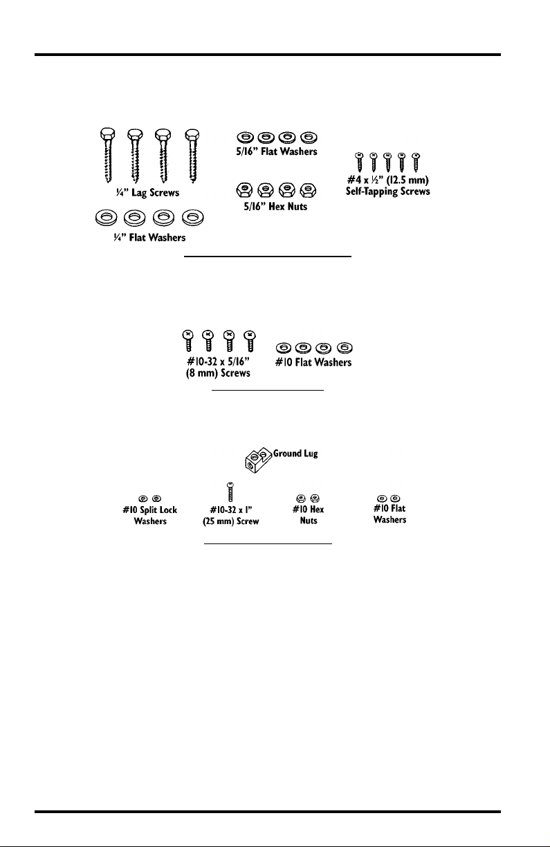
The mounting hardware kit included with the shelter includes the following
components. Please make sure that you have all the components before continuing.
M
OUNTING HARDWARE KIT COMPONENTS
The back panel mounting kit included with the shelter includes the following
components. Please make sure that you have all the components before continuing.
B
ACK PANEL MOUNTING KIT
The ground lug kit included with the shelter includes the following components. Please make sure that you have all the components before continuing.
G
ROUND LUG KIT COMPONENTS
Page 2 Complete System Shelter
Page 3
OOLS
T
AND
You may need some of the following tools and materials in order to install the
shelter.
✦
✦
✦
✦
✦
✦
✦
✦
✦
✦
✦
ATERIALS
M
System Components
You will need the various system components you plan to install inside
the shelter. Some sample installation configurations are shown in “Sample CSS Configurations” on page 5.
Medium Flat Head Screwdriver
Medium Phillips Head Screwdriver
Wrench or 3/8” Nut Driver
Large Adjustable Wrench (1 3/8” Opening)
Electric Drill with #43 (.089”, 2.25 mm) and #36 (.106”, 2.70 mm) Drill Bits
Wire Cutter
Wire Stripper or Knife
Pliers
Electrical Tape and/or Silicone Caulking
Double-Sided Tape
N
EEDED
FOR
NSTALLATION
I
NSTALLING
I
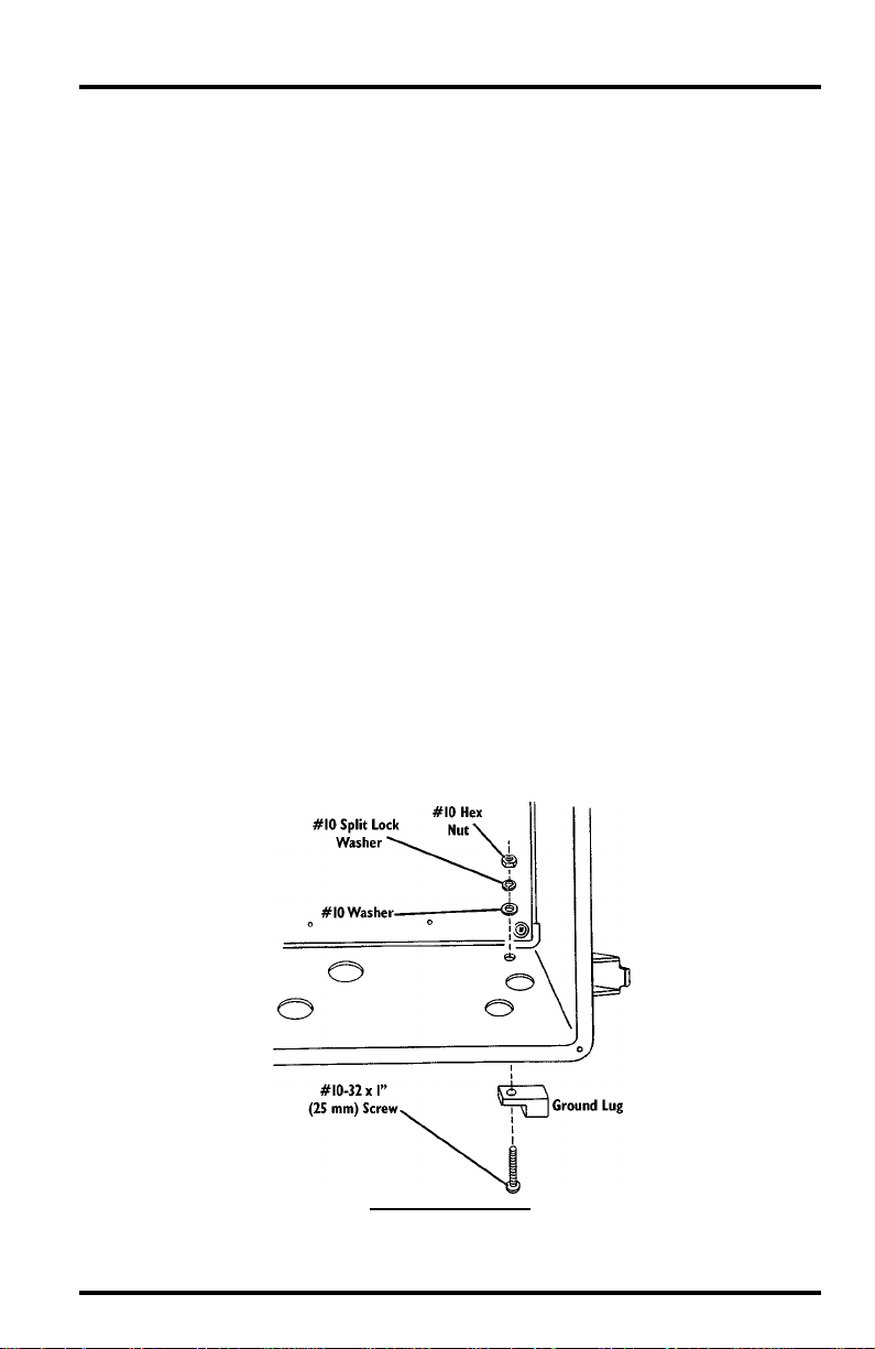
Install the ground lug using a #10-32 screw, #10 washer, #10 split lock washer,
and #10 hex nut as shown below.
Tools and Materials Needed for Installation Page 3
ROUND
G
L
UG
I
NSTALLING
G
ROUND
L
UG
Page 4
NSTALLING
I
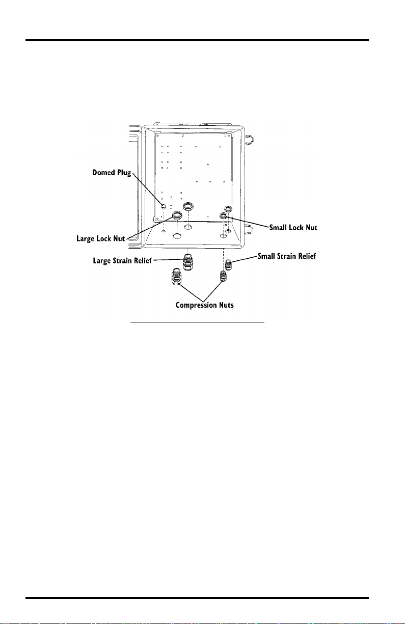
Install strain reliefs and the domed plug in the CSS as shown below. You will
need to install the strain reliefs before running cables into the CSS. Secure the
strain reliefs by tightening the lock nuts. Do not tighten the compression nuts
until you have completed your installation (see “Securing Cables” on page 15).
S
TRAIN
R
I
NSTALLING
ELIEFS
S
AND
TRAIN
R
D
ELIEFS
OMED
D
AND
P
OMED
LUG
P
LUG
Page 4 Complete System Shelter
Page 5
AMPLE
S
CSS C
ONFIGURATIONS
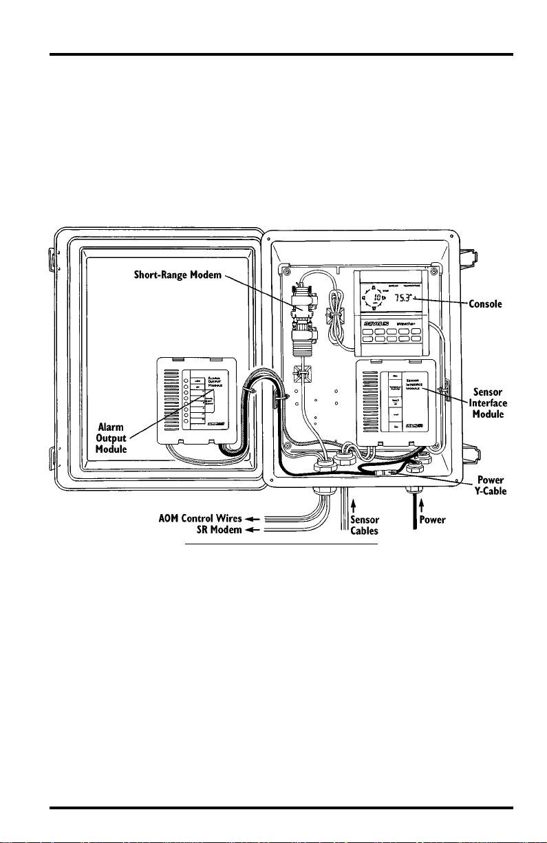
The illustrations below show two sample CSS installations. Consult the installation manuals supplied with system components for wiring instructions.
Console, Sensor Interface Module, Alarm Output Module, and Short-Range Modem
The illustration below shows a CSS installation which includes the console,
sensor interface module (SIM), Alarm Output Module (AOM), and ShortRange Modem (SR Modem).
C
, SIM, AOM, SR M
ONSOLE
ODEM
I
NSTALLATION
Sample CSS Configurations Page 5
Page 6

Console, Protected Junction Box, Link Isolator, and Solar Power Kit
The illustration below shows an CSS installation which includes the console,
Protected Junction Box, Link Isolator, and Solar Power Kit. In this installation,
you would bring a laptop computer to the CSS, plug it into the isolator, and
download data from the WeatherLink.
C
ONSOLE
, P
ROTECTED
J
UNCTION
B
, L
I
,
S
P
OX
INK
SOLATOR
AND
OLAR
OWER
K
IT
Page 6 Complete System Shelter
Page 7

OUNTING
M
THE
CSS
The instructions below take you through the procedure necessary to mount the
shelter against a wall or post, on a small pipe, or on a large pipe.
Mounting the Shelter on a Wall or Post
Attach the shelter to the mounting surface in the desired location using the
large screws and 1/4” flat washers as shown below. Use a pencil or a centerpunch to mark the location of the pilot holes.
M
OUNTING
W
ALL
P
OR
OST
ON
A
Mounting On a Pipe
Mount the CSS onto a pipe, outside diameter between 1 1/2” and 2 3/8”
(38mm and 60mm), using the 2 1/4” U-bolt, saddles, 5/16” washers, and 5/16”
hex nuts as shown below. For a smaller pipe, outside diameter between 3/4”
and 1 1/4” (19 mm and 31mm), use 1 1/2” U-Bolts (not provided).
M
OUNTING
P
ON
A
IPE
Mounting the CSS Page 7
Page 8

NSTALLING
I
The sections below show where and how the various system components are
installed into the CSS.
Note: You will need to consult the various installation manuals supplied with each system component
Installing the Back Panel
Use a #10-32 x 5/16” (8 mm) screw and #10 washer to attach the back panel to
the shelter. If installing the SR Modem or a similarly-sized component. you
must attach cable ties to the back panel before installing it. See “Installing
Short-Range Modem or Similar-Sized Equipment” on page 12 for details.
OMPONENTS
C
for instructions on wiring your installation.
INTO
THE
CSS
I
Page 8 Complete System Shelter
NSTALLING
THE
B
P
ACK
ANEL
Page 9

Installing a Module
You may install any of the following modules into the CSS: sensor interface
module, Protected Junction Box, Alarm Output Module (AOM), or Interface
Cable Adapter Module. You may mount the AOM on the door of the CSS
(because the AOM does not require grounding). All other modules should be
mounted in the shelter’s main box. To install the AOM in the cover, attach the
double-stick pads to the base of the AOM and use the double-stick pads to
secure the AOM to the door of the shelter in the location shown below. To
mount a module in the shelter’s main box, use the #4 x 1/2” (12.5 mm) self-tapping screws as shown below.
I
NSTALLING
M
A
ODULE
When grounding modules installed in the shelter’s main box, use the ground
jumpers supplied with the CSS to connect the terminals inside the “module” to
the ground lug as shown below Use a #10-32 screw, #10 washer, #10 split lock
washer, and #10 hex nut to secure the ground jumper to the ground lug.
G
ROUNDING MODULES
(I
NDUSTRIAL
SIM S
HOWN HAS
2 G
ROUND JUMPERS
)
Installing Components into the CSS Page 9
Page 10

Installing a Console
If you are not installing the 6.5-Amp-Hour Battery in the CSS, install a console
in the CSS using the #4 x 1/2” (12.5 mm) self-tapping screws and nylon insulators as shown below.
I
NSTALLING A CONSOLE
(NO B
ATTERY INSTALLED
)
If you are installing the 6.5-Amp-Hour Battery in the CSS, install the console
onto the battery cover plate using the #4 x 1/2” (12.5 mm)
machine screws
and nylon insulators supplied with the Solar Power Kit (the self-tapping
screws might cause you to inadvertently puncture the battery).
I
NSTALLING A CONSOLE
(B
ATTERY INSTALLED
)
Page 10 Complete System Shelter
Page 11

Installing a Small Junction Box
You may install the small junction box into the CSS, using double-stick pads,
double-sided tape, or the screws shown below. If using the screws, you will
have to drill a hole in one of the locations shown below using the indicated
drill bit. Use a pencil or a center-punch to mark the location of the hole before
drilling.
I
NSTALLING A SMALL JUNCTION BOX
Installing Components into the CSS Page 11
Page 12

Installing Link Isolator
Use double-stick pads or double-sided tape to install the Link Isolator in the
CSS as shown below. Use cable tie mounts to secure the cable.
INSTALLING A LINK ISOLATOR
Installing Short-Range Modem or Similar-Sized Equipment
Install the Short-Range Modem (SR Modem) into the CSS by using cable ties to
secure VELCRO
®
straps (provided with the SR Modem) to the back wall of the
CSS. Then use the VELCRO straps to secure the SR Modem and adapter in
place. Consult the SR Modem manual for detailed instructions.
SR MODEM INSTALLATION
Page 12 Complete System Shelter
Page 13

Installing a Heater
Install the shelter heater as shown below. Note that you must install the heater
insulation blankets before installing the heater. Consult the shelter heater manual for more complete instructions.
INSTALLING HEATER
Installing Surge Protectors
To install 2- or 4-wire Surge Protectors in the CSS, you will need to obtain a
ground terminal (available free from Davis). The ground terminal includes all
hardware necessary to install the surge protector as shown below. Connect the
ground jumper to the surge protectors and the ground lug. Consult the surge
protector manual for instructions on wiring the surge protectors.
INSTALLING SURGE PROTECTOR
Installing Components into the CSS Page 13
Page 14

GROUNDING THE CSS
Connect the CSS to ground using the provided ground wire. If you anticipate
heavy surges, you may wish to use a heavier wire, strap, or multiple wires. Cut
the ground wire to the length required to reach from the CSS to a suitable
ground, such as Davis Instruments’ Grounding Kit (Product #7780). The
ground wire should be as short as possible. Strip both ends of the ground wire
(remove the spade lug if necessary) and insert one end into the ground lug.
Secure in place by tightening the ground lug screw. Attach the other end to a
suitable ground.
GROUNDING THE CSS (INDUSTRIAL SIM SHOWN)
Page 14 Complete System Shelter
Page 15

SECURING CABLES
Secure cable to the inside of the shelter using self-adhesive cable tie mounts
and cable ties. When finished installing components, tighten the compression
nuts on the strain reliefs to secure the cables and create a weather-r esistant seal.
If there is a large air space around the cables, fill the space by wrapping the
cables in electrical tape and/or sealing with silicone caulking.
SECURING CABLES
Securing Cables Page 15
Page 16

Product Number: 7724
Davis Instruments Part Number: 7395-113
Complete System Shelter
Rev. C Manual (7/7/99)
Controlled Online: DI:WM:Accessories:Complete System Shelter
This product complies with the essential protection requirements of the EC EMC Directive 89/336/EC.
© Davis Instruments Corp. 1999. All rights reserved.
VELCRO is a registered trademark of Velcro Industries, Manchester, NH.
3465 Diablo Avenue, Hayward, CA 94545-2778
510-732-9229 • Fax: 510-732-9188
E-mail: info@davisnet.com • www.davisnet.com
 Loading...