

Davis 7716 Installation Manual
M
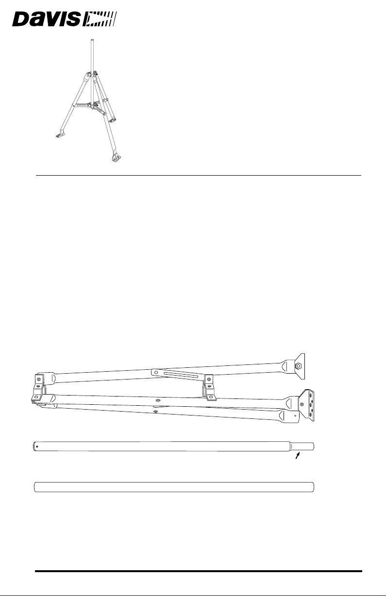
For use with Davis’s Wireless, EZ-Mount, and Vantage Pro Weather Stations,
the Mounting Tripod simplifies installation. The tripod supports the sensor
array, and features an adjustable foot pad which enables mounting on any surface: flat, inclined, or level. The anemometer extension tube can be used to elevate the anemometer in installations where wind flow obstruction is a concern.
OMPONENTS
C
The Mounting Tripod includes the following poles and mounting hardware.
Please make sure you have everything you need before beginning.
OUNTING
T
RIPOD
Poles
Tripod
Anemometer
Extension
Tube
(swaged end)
Long
Extension
Tube
Product # 7716
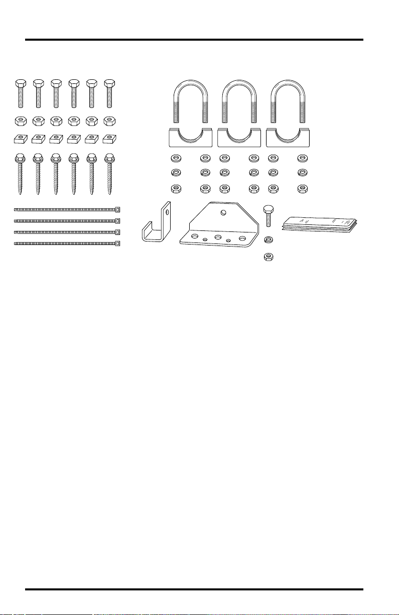
Hardware
Cable Ties
OOLS FOR SETUP
T
✦
Adjustable wrench
Compass or local area map
✦
✦
Drill with 3/16" or 13/64" (5 mm) bit for the 1/4" lag screws
5/16" Bolts
Hex Nuts
Square Nuts
1/4" x 2"
Lag Screws
Vertical Stop
Plate
5/16" x 1-1/2"
U-Bolts
1-1/8" Saddles
5/16" Flat Washers
5/16" Lock Washers
5/16" Hex Nuts
Pitch Pads
Foot Bracket and
1/4" Bolt
ONTENTS OF THIS MANUAL
C
✦
Tripod assembly, page 3
✦
Mounting the tripod, page 5
✦
Attaching the ISS to the anemometer extension tube, page 6
✦
Securing the ISS on the tripod, page 7
✦
Attaching the sensor array on EZ-Mount and Wireless systems, page 8
✦
Using the anemometer extension tube on EZ-Mount and Wireless, page 9
Page 2
RIPOD
T
SSEMBLY
A
Follow the instructions below to assemble the tripod.
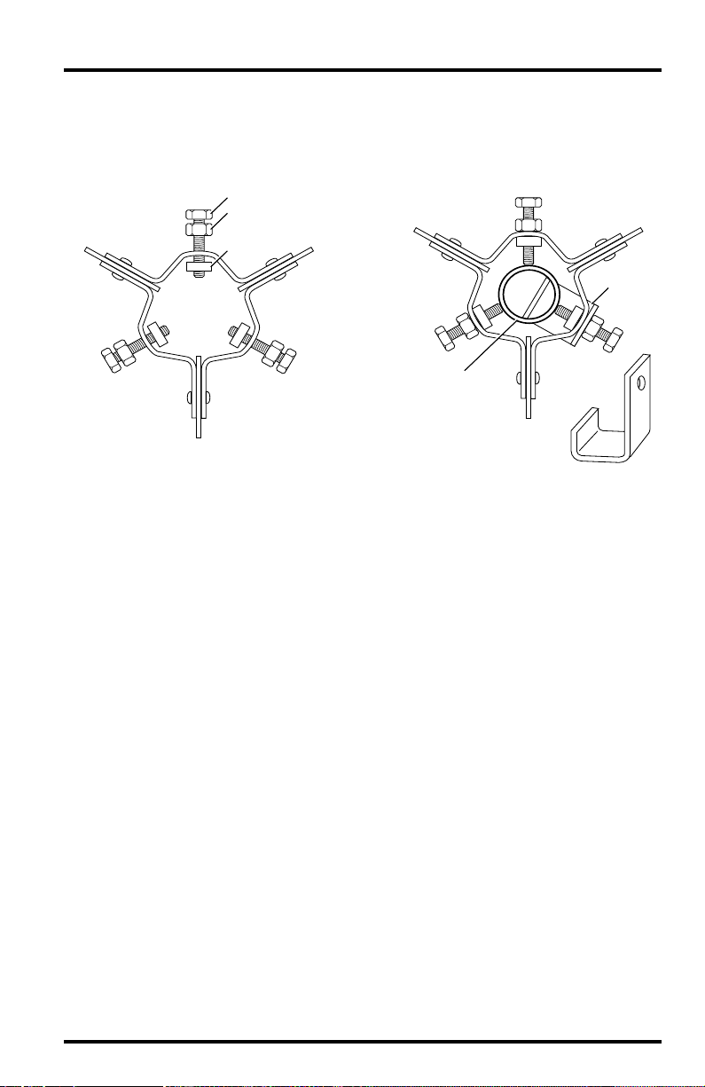
Assemble nuts and bolts
in Tripod brackets.
Do not tighten.
1. Unfold the tripod so the two foot pads which come pre-installed on the tripod legs are
flat on the ground.
2. Thread a hex nut almost all the way onto all six of the 5/16" bolts.
5/16" Bolt
Hex Nut
Use Vertical Stop Plate
on one of the lower
bracket bolts.
Square Nut
Long
Extension
Tube
Slide Long Extension Tube
through center of Tripod brackets.
Tighten nuts and bolts.
Vertical
Stop Plate
3. Insert one of the 5/16" bolts into the hole in vertical stop plate.
4. Insert the 5/16" bolt with vertical stop plate into one of the holes in the tripod's lower
bracket and thread a square nut onto the end of the bolt, on the inside of the bracket.
Do not thread the square nut too far up the bolt.
5. Repeat this procedure for the remaining 5/16" bolts. Place them into the holes in both
the top and bottom tripod brackets, threading a square nut on the end of each bolt.
Do not thread the square nuts too far up the bolts.
6. Insert the long extension tube into the tripod, sliding it through the brackets.
The vertical stop plate should keep the tube from sliding all the way
through.
7. Secure the extension tube by tightening the square and hex nuts on the 5/16" bolts
until the bolts hold the tube in place securely.
Tripod Assembly Page 3
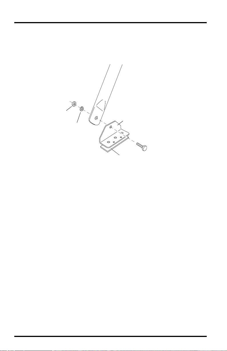
8. Attach the foot bracket to the tripod leg as shown below.
Apply pitch pads to the bottom of the foot bracket and the two foot brackets
that come pre-installed on the tripod.
Front Leg
Hex
Nut
Foot Bracket
Lock
Washer
1/4" Bolt
Pitch Pad
Page 4
 Loading...