

Page 1
R
ADIATION SHIELD
M
ANUAL
This instruction manual will take you step-by-step through the process of
assembling and mounting your Radiation Shield. Please take the time to read
through this manual before beginning the process.
C
OMPONENTS
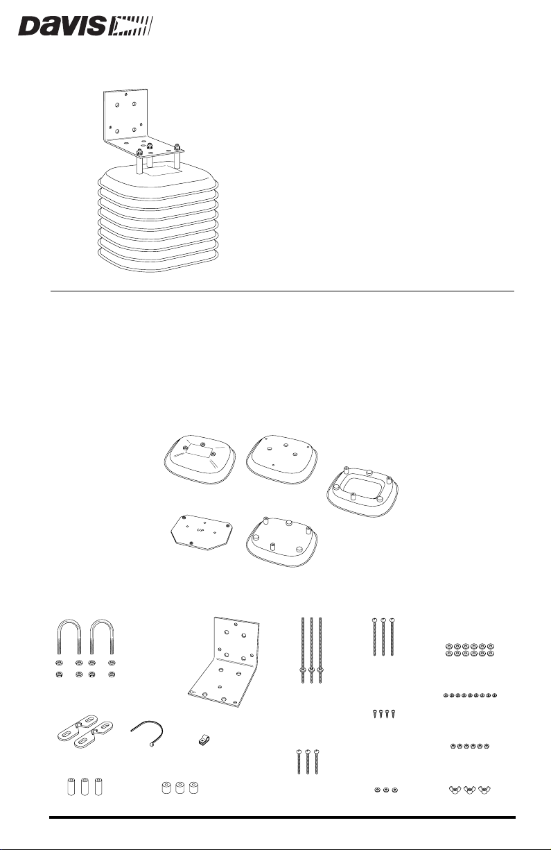
The Radiation Shield includes the following components. Please make sure
you have all listed components before continuing.
✦
Radiation Shield Parts
✦
1" (25 mm) Spacers
Cover Plate
Support Plate
Installation Hardware Kit
1-1/2" U-Bolts
1/4" Flat Washers
1/4" Hex Nuts
Wall Mount Bracket
Cable TieClip Mounts
Cable Clamp
1/2" (13 mm) Spacers
Flat Plate
Closed Plates (3)
#8 x 5"
(127 mm long)
Threaded Studs
with push nuts
installed
#8 x 1-3/4"
(44 mm long)
Pan Head Screws
Open Plates (3)
#8 x 2-3/4"
(70 mm long)
Pan Head Screws
#4 x 1/2"
(13 mm long)
Pan Head
Self-Threading
Screws
#4 Flat Washers
#8 Flat Washers (12)
#8 Split Lock
Washers (9)
#8 Hex Nuts (6)
#8 Wing Nuts (3)
Product # 7714
Page 2

OOLS AND MATERIALS NEEDED
T
In addition to the components listed above, you may need some of the following tools and materials.
Small Phillips-Head Screwdriver and Medium Slotted-Head Screwdriver
✦
Wrench or Pliers
✦
✦
Drill with 3/16” Drill Bit (4.7 mm)
To drill pilot holes if attaching Radiation Shield to the top of a post.
Adjustable Wrench or 11/32” Wrench and 7/16” Wrench
✦
To tighten hex nuts (11/32” wrench) or to drive lag screws into wall or
post (7/16” wrench).
Four 1/4” x 1 1/2” Lag Screws (38 mm long)
✦
To attach Radiation Shield to a post or wall.
✦
Three #8-32 x 1” Screws (25 mm long)
To attach Radiation Shield over the top of a post (if #8 x 2 3/4” pan head
screws (provided) create clearance problems).
Tape
✦
To hold screws in place when assembling Radiation Shield.
L
OCATION
T
IPS
✦
The Radiation Shield works best when in a location with a steady breeze. Mount
away from fences, buildings, trees, or other obstructions.
Install over plants or soil if possible.
✦
✦
Do not install over or near sprinklers. The Radiation Shield is not designed to protect the sensor from water sprayed upwards.
If attaching to a building, the preferred location would be on the north side in the
✦
Northern Hemisphere and on the south side in the Southern Hemisphere.
Page 2 Radiation Shield Manual
Page 3
NSTALLATION
I
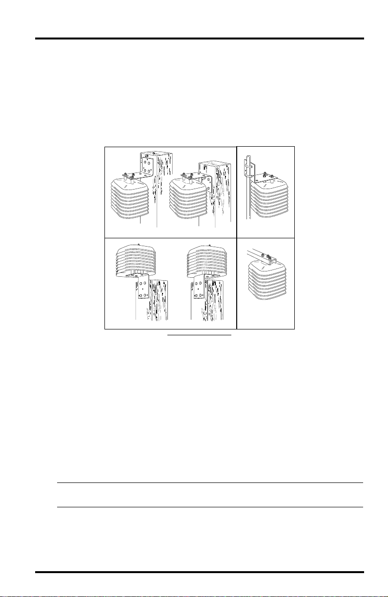
The Radiation Shield may be mounted in four basic orientations: on the side of
a wooden post or a wall, on a metal pipe with outside diameter between 1” and
1 1/4” (25 mm and 31 mm), on top of a wood post, or onto Davis’ Sensor
Mounting Arm. Each of these configurations is pictured below. You should
determine ahead of time which orientation best suits your purpose because the
installation instructions differ slightly depending on how you plan to mount
the Radiation Shield.
PTIONS
O
Mounting on the Side of a Post or Wall
Mounting on Top of a Post
I
NSTALLATION
O
PTIONS
Mounting on a Pipe
Mounting on the
Sensor Arm
A
TTACHING
The Radiation Shield can house the External Temperature Sensor, Stainless
Steel Temperature Probe, or External Temperature/Humidity Sensor.
Attaching the External Temperature Sensor or the Stainless Steel
Temperature Probe to the Radiation Shield
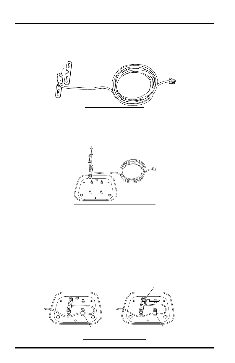
In order to attach the External Temperature Sensor or the Stainless Steel Temperature Probe to the Radiation Shield, you will need a closed plate, both clip
mounts, the cable clamp, three #4 x 1/2” pan head self-threading screws, three
#4 flat washers, and the temperature sensor/probe.
Note: The following illustrations show the installation process for the External Temperature Sensor. The
1. Place the sensor cable into the notch on one of the clip mounts and hold it in place.
Make sure to hold the clip mount so the raised semi-circle at the top of the
notch faces up.
Installation Options Page 3
S
THE
directions may be used for the Stainless Steel Temperature Probe, as well.
ENSOR
Page 4
2. Position the second clip mount over the first, with the notch facing in the opposite
direction, securing the sensor cable between the two notches.
When positioning the second clip mount, make sure the raised semi-circle
faces down.
Clip Mounts
P
C
I
C
LACING
ABLE
NTO
M
LIP
OUNTS
3. Position the clip mounts over two of the mounting posts on the closed plate.
Make sure you orient the clip mounts as show in the figure below.
4. Attach the clip mounts to the mounting posts using two of the #4 x 1/2” pan head
self-threading screws and two of the #4 flat washers.
#4 x 1/2" Screw
#4 Flat Washer
TTACHING
A
LIP
OUNTS
TO
C
M
ADIATION
R
S
HIELD
5. Once secured, adjust the position of the sensor so the sensor and approximately 1/4”
(6 mm) of cable protrude from the clip mounts.
6. Place the cable clamp around the sensor cable approximately 8” (20 cm) from the
sensor.
7. Secure the cable clamp to one of the remaining mounting posts (using a #4 x 1/2” pan
head self-threading screw and a #4 flat washer) so that a loop of cable is formed.
Make sure to mount the clamp with the flat side up and the bulge side
down. Tighten the screw completely so that the cable cannot move within
the cable clamp. If using the Stainless Steel T emperatur e Pr obe, wrap a cable
tie around the sensor and cable as shown below to hold the probe in place.
Cable Tie
Cable Clamp
External Temperature Sensor
S
ECURING
Stainless Steel Temperature Probe
C
C
ABLE
WITH
ABLE
C
LAMP
Cable Clamp
Page 4 Radiation Shield Manual
Page 5
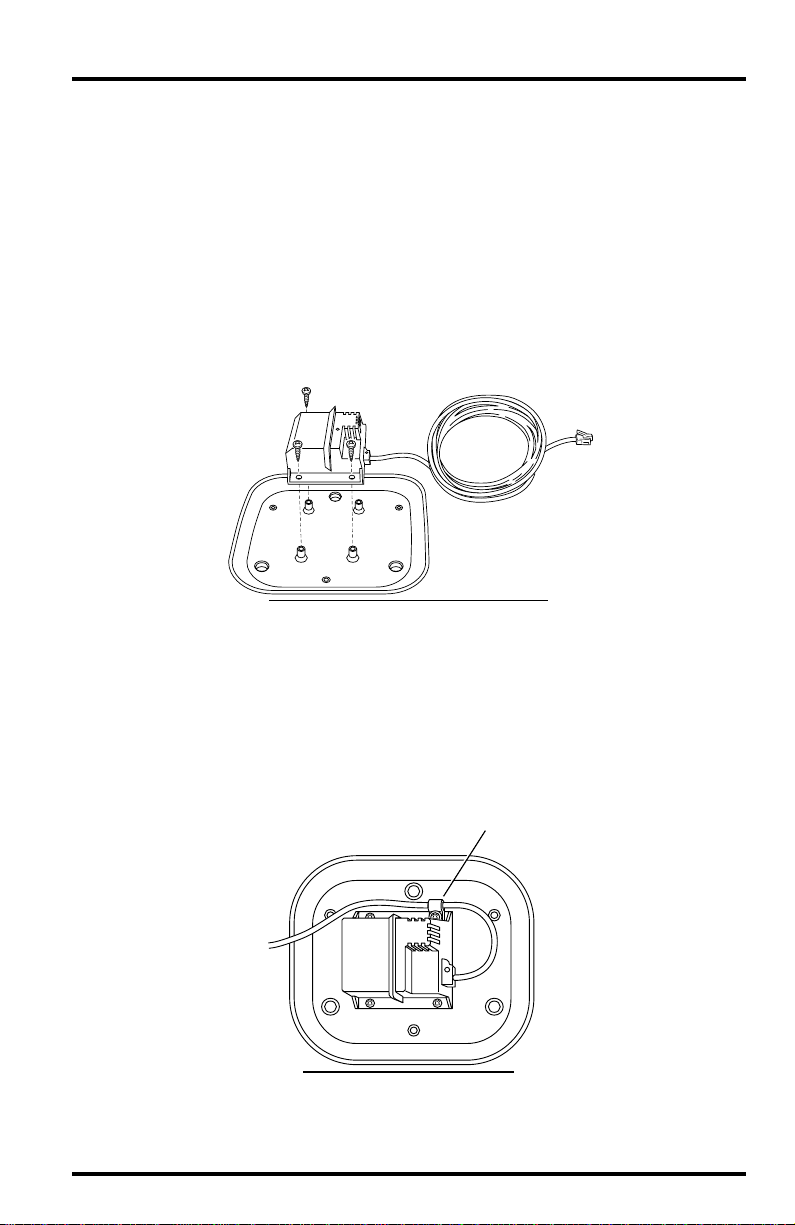
Attaching the Temperature/Humidity Sensor to the Radiation Shield
In order to attach the External Temperature/Humidity Sensor (T/H Sensor) to
the Radiation Shield, you will need a closed plate, four #4 x 1/2” pan head
self-threading screws, one # 4 flat washer, and the T/H Sensor.
1. Position the T/H Sensor over the four mounting posts on the closed plate, lining up the
holes in the mounting posts with the holes in the T/H Sensor’s casing.
Make sure you orient the T/H Sensor as shown in the figure below (with the
long side of the sensor parallel to the long side of the plate).
2. Using three #4 x 1/2” pan head self-threading screws, attach THREE CORNERS of the
T/H Sensor to the closed plate.
Do not attach the final corner yet.
#4 x 1/2" Screws (3)
RIENTING
AND
O
TTACHING
A
EMP
UM
/H
S
ENSOR
T
3. Place the cable clamp around the sensor cable approximately 4” (10 cm) from the T/H
Sensor.
4. Attach the cable clamp to the remaining corner of the T/H Sensor and to the closed
plate (using a #4 x 1/2” pan head self-threading screw and a #4 flat washer) so that a
loop of cable is formed.
Make sure to mount the clamp with the flat side up and the bulge side
down. Tighten the screw completely so that the cable cannot move within
the cable clamp.
Cable Clamp
S
C
C
ECURING
ABLE
WITH
ABLE
C
LAMP
Attaching the Sensor Page 5
Page 6

Attaching the Support Plate to the Cover Plate
To attach the support plate, you will need the cover plate, the support plate,
three #8 x 2 3/4” pan head screws, three 1” spacers, three #8 flat washers, thr ee
#8 split lock washers, and three #8 hex nuts.
1. Slide the three #8 x 2 3/4” pan head screws up through the non-threaded holes in the
shield support plate.
Make sure the side of the support plate marked “UP” is in fact on top as you
slide the screws in from the bottom.
2. Place the cover plate over the screw ends protruding from the support plate.
3. Place a 1” spacer over each of the screw ends.
4. Secure the support plate and spacers to the cover plate using a #8 flat washer, #8
split lock washer, and #8 hex nut on each of the screw ends.
Tighten until the support plate is firmly attached to the cover plate.
#8 Hex Nut
#8 Lock Washer
#8 Flat Washer
1" Spacer
Cover Plate
Support Plate
#8 x 2-3/4"
Pan Head Bolt
C
P
OVER
LATE
A
SSEMBLY
Cover Plate Assembly
Page 6 Radiation Shield Manual
Page 7

Assembling the Plates and Studs
To assemble the plates and studs you will need the cover plate assembly as
well as the flat plate and closed plate with sensor, three #8 x 5” threaded studs
with attached #8 push nuts, three #8 flat washers, three #8 split lock washers,
and three plastic retainers.
1. Slide each of the three #8 x 5” (127 mm) threaded studs, with push nuts installed,
through each of the three holes in the closed plate, flat plate, support plate and cover
plate.
When inserting the threaded studs make sure that the short end (when measured from the push nut) goes through the plates. Screw the short end of the
threaded stud in until the cupped side of the push nut bottoms inside the
recess of the closed sensor plate. Tighten as much as you can by hand.
Threaded Studs
with push nuts
Closed Plate
with Temp/Hum
Sensor
Flat Plate
Cover Plate
Assembly
P
LATES
AND
Support Plate
S
A
TUDS
SSEMBLY
Plates and Studs
Assembly
2. Place the Plates and Studs Assembly aside and proceed to the appropriate instruc-
tions for your installation.
If you are attaching the shield to the side of a post, to a pipe or to the Davis
Sensor Mounting Arm, continue with the instructions on page 8.
If you are attaching the shield to the top of a post, continue with the instructions on page 9.
Attaching the Sensor Page 7
Page 8

SSEMBLING
A
IDE
S
M
OUNTING ARM
OF
The following instructions explain how to assemble the Radiation Shield for
installation on the side of a post, on a pipe, or on Davis’ Sensor Mounting Arm.
Please note, however, that if you plan to mount the Radiation Shield on top of a
post, you should follow the instructions in “Assembling the Radiation Shield
to Attach to the Top of a Post” on page 9.
1. Slide the three open plates and the two remaining closed plates over the threaded
stud ends protruding from the top of the plate and studs assembly.
THE
P
A
OST, TO A PIPE, OR ON THE SENSOR
Closed Plate
Closed Plate
Open Plate
Open Plate
ADIATION
R
HIELD
S
TO
TTACH
A
TO
THE
#8 Wing Nut
Open Plate
Plates and Studs
Assembly
SSEMBLING THE RADIATION SHIELD PLATES
A
2. Place flat washers, lock washers and plastic wing nuts over the protruding stud ends.
3. Rest the partially assembled Radiation Shield on a flat surface and proceed with
“Mounting the Radiation Shield” on page 12.
Page 8 Radiation Shield Manual
Complete Plate
Assembly
#8 Lock Washer
#8 Flat Washer
Page 9

SSEMBLING THE RADIATION SHIELD TO ATTACH TO THE
A
OP OF A POST
T
The instructions for assembling the Radiation Shield differ slightly if you plan
to mount the Radiation Shield on top of a wooden post. Follow the instructions
below if (and only if) you plan to ultimately mount the Radiation Shield on top
of a wooden post.
Attaching Mounting Bracket
To attach the mounting bracket you will need a closed plate, the mounting
bracket, three 1/2” spacers, three #8 x 2 3/4” pan head screws, six #8 flat washers, three #8 split lock washers, and three #8 hex nuts. You will also need a drill
with a 3/16” (4.7 mm) drill bit.
Note: Y ou will need to supply three #8 x 1” screws if you plan to mount the Radiation Shield over the top of
the post (not preferred), instead of suspending it over the side edge.
MOUNTING ON TOP OF A POST
1. Using the power drill with 3/16” (4.7 mm) drill bit, drill three holes through one of the
closed plates in the locations marked by the small dimples on the bottom of the plate.
Do not use the closed plate to which you attached the sensor.
3/16" (4.7 mm) Drill Bit
Closed
Plate
DRILLING HOLES IN CLOSED PLATE
Assembling the Radiation Shield to Attach to the Top of a Post Page 9
Page 10

2. Place a #8 flat washer over the end of each of the #8 x 2 3/4” pan head screws.
As long as the extra length of screw end protruding from the bottom of the
Radiation Shield doesn’t create clearance problems when mounting the
Radiation Shield, you can use the 8 x 2 3/4” pan head screws. If a clearance
problem exists, you will need to use #8 x 1” screws instead (not included).
3. Slide the three #8 x 2 3/4” pan head screws (with washers) up through the holes you
just drilled.
4. At this point, you may want to place a small piece of tape over each of the screw heads
to keep the screws in place as you continue.
5. Place a 1/2” spacer over each of the screw ends protruding from the closed plate.
6. Slide the mounting bracket over the screw ends protruding from the closed plate.
7. Secure the mounting bracket to the closed plate using a #8 flat washer, a #8 split
lock washer, and a #8 hex nut on each of the screw ends.
Tighten until the mounting bracket is firmly attached to the closed plate.
#8 Hex Nut
#8 Lock Washer
#8 Flat Washer
1/2" Spacer
Closed
Plate
#8 Flat Washer
#8 x 2-3/4" Screw
ATTACHING MOUNTING BRACKET
Page 10 Radiation Shield Manual
Page 11

Assembling the Radiation Shield
To assemble the Radiation Shield plates you will need the plates and studs
assembly, as well as the rest of the plates, three #8 flat washers, three #8 split
lock washers, and three plastic wing nuts.
1. Slide the three open plates and the two remaining closed plates over the threaded
stud ends protruding from the top of the plate and studs assembly.
Plates and Studs
Assembly
Open Plate
Complete Plate
Open Plate
Assembly
Open Plate
#8 Flat Washer
#8 Lock Washer
#8 Wing Nut
Closed Plate
Closed Plate
with Bracket
attached
2. Place flat washers, lock washers and plastic wing nuts over the protruding stud ends.
Continue with “Mounting the Radiation Shield” on page 12.
Assembling the Radiation Shield to Attach to the Top of a Post Page 11
Page 12

MOUNTING THE RADIATION SHIELD
Follow the instructions below to mount the Radiation Shield. There are separate sections for each of the basic mounting options. You should modify the
instructions as necessary to fit your needs.
Mounting On the Side of a Post or Wall
In order to mount the Radiation Shield onto the side of a post or wall, you will
need the Radiation Shield assembly, three #8 split lock washers, three #8 flat
washers, and three #8 hex nuts. You will also need to supply four 1/4” x 1 1/2”
lag screws.
1. Using four 1/4” x 1 1/2” lag screws (not included), attach the mounting bracket to the
mounting surface in the desired location.
ATTACHING MOUNTING BRACKET TO THE SIDE OF A POST
2. Slide the stud ends protruding from the top of the Radiation Shield assembly into the
holes on the mounting bracket.
3. Secure the mounting bracket to the Radiation Shield using a #8 flat washer, #8 split
lock washer and #8 hex nut one each of the stud ends.
Tighten until the mounting bracket is firmly attached to the Radiation Shield
#8 Hex Nut
#8 Lock Washer
#8 Flat Washer
Complete Plate
Assembly
ATTACHING RADIATION SHIELD TO MOUNTING BRACKET
Page 12 Radiation Shield Manual
Page 13

Mounting on the Sensor Mounting Arm
In order to mount the Radiation Shield onto the Sensor Mounting Arm, you
will need the Radiation Shield assembly, three #8 split lock washers, three #8
flat washers, and three #8 hex nuts, and the Sensor Mounting Arm.
1. Slide the stud ends protruding from the top of the Radiation Shield assembly into the
holes on the Sensor Mounting Arm.
2. Secure the Radiation Shield to the Sensor Mounting Arm using a #8 flat washer, #8
split lock washer and #8 hex nut one each of the stud ends.
Tighten until the Radiation Shield is firmly attached to the Sensor Mounting
Arm.
#8 Hex Nut
#8 Lock Washer
#8 Flat Washer
Complete Plate
Assembly
ATTACHING RADIATION SHIELD TO SENSOR MOUNTING ARM
Mounting on a Pipe
In order to mount the Radiation Shield onto a metal pipe with outside diameter
between 1” and 1 1/4” (25 mm and 31 mm), you will need the Radiation Shield
assembly, three #8 split lock washers, three #8 flat washers, three #8 hex nuts,
two 1 1/2” U-bolts, four 1/4” flat washers, and four 1/4” hex nuts.
1. Slide the stud ends protruding from the top of the Radiation Shield assembly into the
holes on the mounting bracket.
Mounting the Radiation Shield Page 13
Page 14

2. Secure the mounting bracket to the Radiation Shield using a #8 flat washer, #8 split
lock washer and #8 hex nut one each of the screw ends.
Tighten until the mounting bracket is firmly attached to the Radiation
Shield.
#8 Hex Nut
#8 Lock Washer
#8 Flat Washer
Complete Plate
Assembly
ATTACHING RADIATION SHIELD TO MOUNTING BRACKET
3. Hold the mounting bracket against the pipe and slide the ends of the two 1 1/2”
U-bolts through the holes in the back of the mounting bracket so that the U-bolts
wrap around the pipe.
4. Secure the mounting bracket to the pipe using a 1/4” flat washer and a 1/4” hex nut on
each end of the 1 1/2” U-bolts.
Tighten until the mounting bracket is firmly attached to the pipe.
1/4" Flat Washer
1/4" Hex Nut
1-1/2" U-Bolts
Complete
Plate
Assembly
ATTACHING MOUNTING BRACKET TO A PIPE
Page 14 Radiation Shield Manual
Page 15

Mounting on Top of a Post
In order to mount the Radiation Shield onto the top of a post, you will need the
Radiation Shield assembly (with mounting bracket already attached). You will
need to supply four 1/4” x 1 1/2” lag screws.
To mount the Radiation Shield, simply use the four 1/4” x 1 1/2” lag screws
(not included), to attach the mounting bracket to the mounting surface in the
desired location.
ATTACHING MOUNTING BRACKET TO THE TOP OF A POST
MAINTENANCE INSTRUCTIONS
✦ The effectiveness of the Radiation Shield will be reduced if the surfaces of the
shield become dirty.
Wipe the surfaces of the shield using a damp cloth to remove dirt etc.
✦ Keep areas between Radiation Shield plates free of debris that may obstruct air
flow e.g., leaves, twigs, webs, nests.
DO NOT remove nesting insects or animals by spraying insect killer of
any kind into the radiation shield because this may damage the sensors
and the Radiation Shield.
Maintenance Instructions Page 15
Page 16

 Loading...