

Page 1
ENSOR TILTING
S
RACKET
B
The Sensor Tilting Bracket (STB) enables you to adjust the position of the solar
radiation sensor and/or the UV sensor to match the angle of the sun’s rays.
Use the STB with the Energy EnviroMonitor™ to match the angle of the solar
radiation sensor to the angle of your solar panels. Use the STB with the Heath
EnviroMonitor™ for maximum temperature-humidity-sun-wind index and/or
UV readings. Do not use the STB when mounting the solar radiation sensor for
use with the GroWeather™. The GroWeather’s ET calculations assume that the
solar radiation sensor is mounted horizontally.
C
OMPONENTS
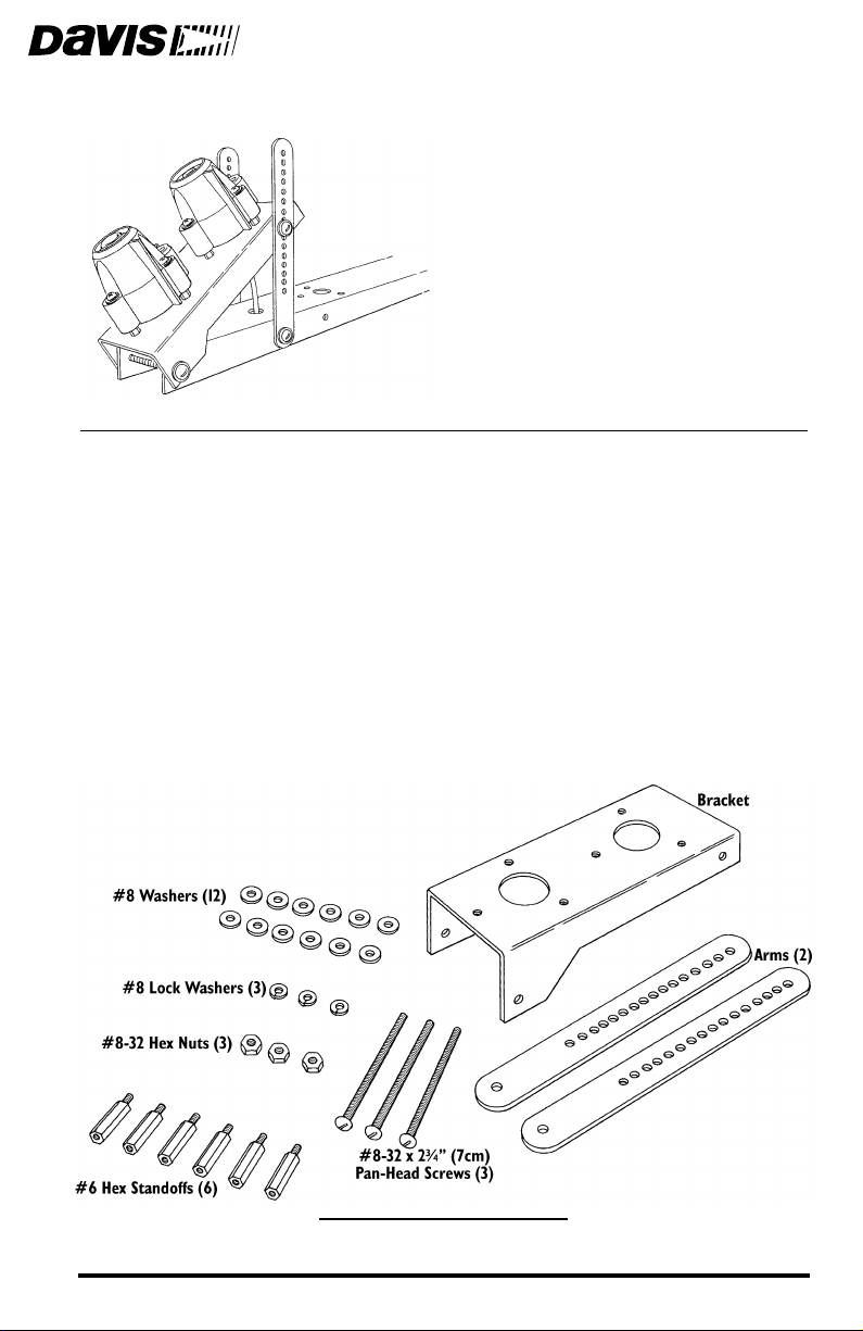
The Sensor Tilting Bracket includes the following components. Please make
sure you have all listed components before continuing.
S
ENSOR TILTING BRACKET COMPONENTS
Product # 7706
Page 2
OOLS AND MATERIALS NEEDED
T
In addition to the components listed above, you will need some of the following tools and materials. Please be sure you have everything you need before
beginning the installation.
Solar Radiation and/or UV Sensor
✦
You will also need the #6-32 x 1-1/2" (38 mm) machine screws, #6 washers, #6 screws retainers, and springs included with the sensor.
Medium Phillips Screwdriver
✦
Wrench or Pliers
✦
✦
Drill with 7/32" (.219", 5.5 mm) Drill Bit
Cable Clips or Weather-Resistant Cable Ties with screw holes or other means for
✦
mounting
U
SING
S
TANDOFFS
TO
A
TTACH
S
ENSOR
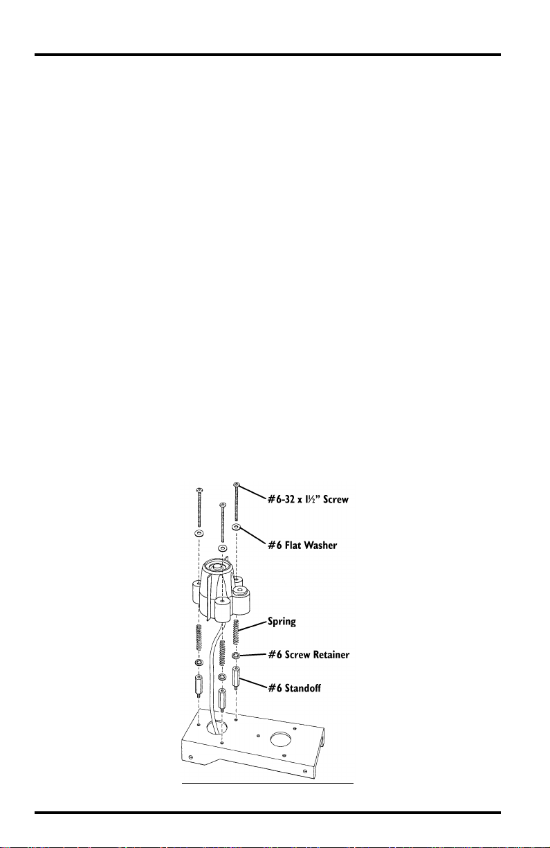
Consult the sensor manual for instructions on attaching the sensor to the
STB. However, if mounting the sensor on the tilting bracket in a location
under 46˚ latitude or in a situation which requires the angle of the tilting
bracket to be less than 28˚, you will need to use the standoffs supplied with
the tilting bracket as shown below. (The standoffs allow enough room
between the bottom of the sensor and the SMA.) The standoffs are made of
aluminum; take care not to overtighten when screwing into the bracket.
Consult the sensor manual for the remaining instructions on attaching the
sensor to the STB.
U
SING
S
TANDOFFS
M
OUNT
THE
S
ENSOR
TO
Page 2 Sensor Tilting Bracket
Page 3
OUNTING
M
THE
ENSOR
S
ILTING
T
RACKET
B
The instructions below explain how to select the correct tilt angle for the STB
and how to mount STB on the Sensor Mounting Arm or on another surface.
The Tilt Angle
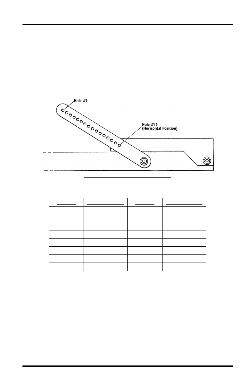
The STB allows you to angle the sensors between 0˚ and 66˚, depending on
which hole in the STB arms you use when mounting the bracket. The illustration below shows the orientation of the holes (from 1 to 16).
S
T
B
A
H
ENSOR
ILT
RACKET
RM
OLE
D
ESIGNATIONS
The table below shows the tilt angle achieved by using any given hole.
H
OLE
#
S
ENSOR
A
NGLE
H
OLE
#
S
ENSOR
A
NGLE
1 66.0˚ 9 32.6˚
2 61.5˚ 10 28.5˚
3 57.3˚ 11 24.4˚
4 53.0˚ 12 20.3˚
5 48.9˚ 13 15.7˚
6 44.7˚ 14 11.4˚
7 40.6˚ 15 6.4˚
8 36.6˚ 16 0.0˚
Mounting the Sensor Tilting Bracket Page 3
Page 4

Determining the Correct Tilt Angle
If you know the angle at which you want to mount the sensor (to match the
angle of a solar panel, for example), use the table in “The Tilt Angle” on page 3
to determine which hole on the STB arms best matches that angle.
To maximize solar radiation or UV readings (and all related readings), start by
determining your latitude. Determine the correct angle (depending on the season during which you want maximum readings) as described below. Finally,
use the table in “The Tilt Angle” on page 3 to determine which hole on the STB
arms best matches that angle.
Note: If desired, you may change the angle of the STB every four months to maximize your readings
year round.
Maximum Readings During Spring or Fall
✦
If you want maximum readings in the Spring or Fall, use your latitude as
the angle (that is, at 45˚ latitude, use an angle of 45˚).
✦
Maximum Readings During Summer
If you want maximum readings in the Summer, subtract 18˚ from your
latitude to determine the correct angle (that is, at 45˚ latitude, use an
angle of 27˚).
✦
Maximum Readings During Winter
If you want to maximize readings in the Winter, add 18˚ to your latitude
to determine the correct angle (that is, at 45˚ latitude, use an angle of
63˚).
For greater accuracy in determining the correct angle, consult a table of the
sun’s declination over the desired time span. The best tilt angle is derived by
subtracting declination from latitude. You may then use the table in “The Tilt
Angle” on page 3 to determine which hole on the STB arms best matches that
angle.
Page 4 Sensor Tilting Bracket
Page 5

Mounting on the Sensor Mounting Arm
Follow the instructions below to mount the STB on the Sensor Mounting Arm (SMA).
1. Make sure that you mount the SMA (or plan to mount the SMA) so the sensor(s) on the
STB point towards the sun at solar noon.
Solar noon occurs halfway between sunrise and sunset; consult your local paper
or the W eatherLink
®
software for sunrise and sunset times. To correctly align
the arm, screw a mounting screw part way into any of the screw positions on
the mounting arm and rotate the arm until the shadow from the screw is parallel to the edge of the sensor arm at solar noon.
2. Attach the STB to the SMA as shown below using the #8-32 screws, #8 washers, #8
lock washers, and #8-32 hex nuts. See “The Tilt Angle” on page 3 to determine which
hole to use on the arms.
Make sure you place three #8 washers between the arms and the SMA. For
clarity, the sensor is not shown in the drawing below.
M
OUNTING
S
ON
THE
ENSOR
M
OUNTING
A
RM
3. Make sure you secure the sensor cable below the SMA as shown in the sensor manual.
Mounting the Sensor Tilting Bracket Page 5
Page 6

Mounting on Alternate Surfaces
You may also mount the STB on a block of wood or a metal bracket.
1. Prepare the mounting surface by drilling two holes using a 7/32" (.219", 5.5 mm) drill
bit in the locations shown below.
P
REPARING
M
OUNTING
S
URFACE
2. Make sure that you position the alternate surface (or plan to position it) so the sensor(s) on the STB point towards the sun at solar noon.
Solar noon occurs halfway between sunrise and sunset; consult your local paper
or the W eatherLink
®
software for sunrise and sunset times.
Page 6 Sensor Tilting Bracket
Page 7

3. Attach the STB to the surface as shown below using the #8-32 screws, #8 washers,
#8 lock washers, and #8-32 hex nuts. See “The Tilt Angle” on page 3 to determine
which hole to use on the arms.
Make sure you place three #8 washers between the arms and the mounting
surface. For clarity, the sensor is not shown in the drawing below.
M
OUNTING
ON
A
AN
LTERNATE
S
URFACE
4. Secure the sensor cable to the mounting surface using cable clips or weather resistant
cable ties with screw holes or other means for mounting.
S
S
ENSOR
C
ABLE
ECURING
Mounting the Sensor Tilting Bracket Page 7
Page 8

Product Numbers: 7706
Davis Instruments Part Number: 7395-108
Sensor Tilting Bracket
Rev. B Manual (10/14/99)
This product complies with the essential protection requirements of the EC EMC
Directive 89/336/EC.
© Davis Instruments Corp. 1997. All rights reserved.
 Loading...