

Page 1
ENSOR
S
M
OUNTING
A
RM
The Sensor Mounting Arm provides an ideal mounting location for all of your
Davis weather station sensors. This manual is designed to take you through the
process required to assemble and mount the Sensor Mounting Arm. Please take
the time to read through this manual before beginning.
C
OMPONENTS
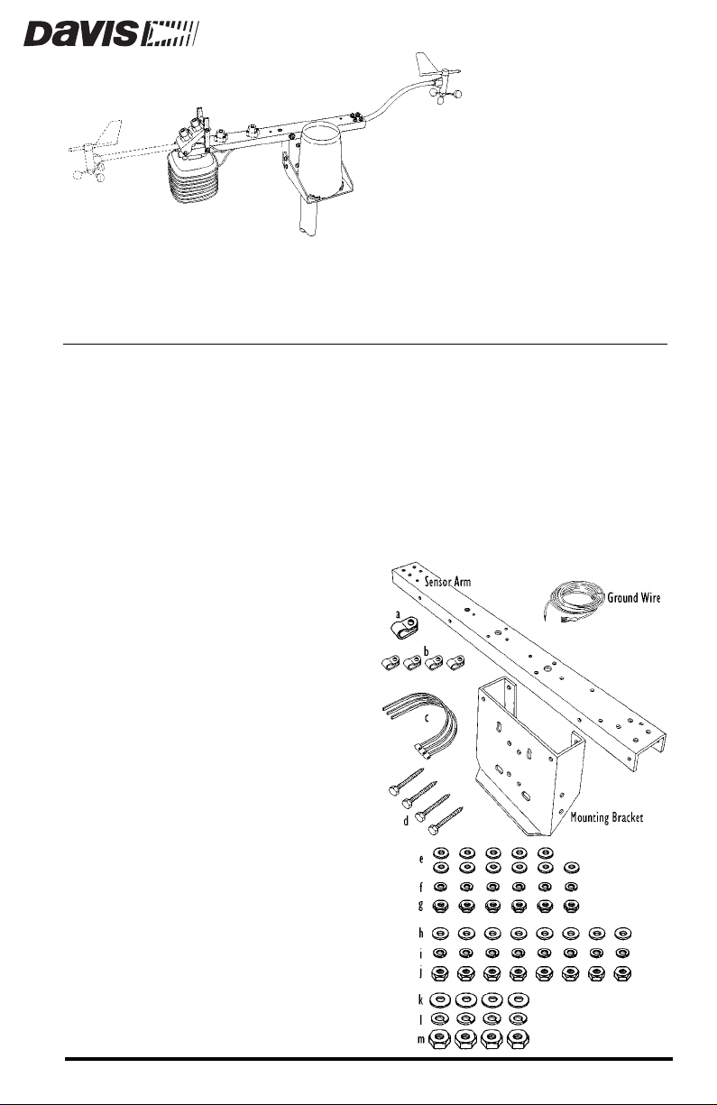
The Sensor Mounting Arm includes the following components. Please make
sure you have all listed components before continuing.
Sensor Arm
✦
✦
Mounting Bracket
✦
16.5-foot (5 m) Ground Wire
Installation Hardware Kit
✦
One 3/8” Cable Clamp
a.
b.
Four 3/16” Cable Clamps
c.
Three 3/8” Cable Ties
d.
Four 1/4” x 1-1/2”
(38 mm) Lag Screws
Eleven #8 Flat Washers
e.
Six #8 Split Lock Washers
f.
Six #8-32 Hex Nuts
g.
Eight 1/4” Flat Washers
h.
i.
Eight 1/4” Split Lock
Washers
j.
Eight 1/4”-20 Hex Nuts
k.
Four 5/16” Flat Washers
Four 5/16” Split Lock
l.
Washers
Four 5/16”-18 Hex Nuts
m.
Product # 7702
Page 2
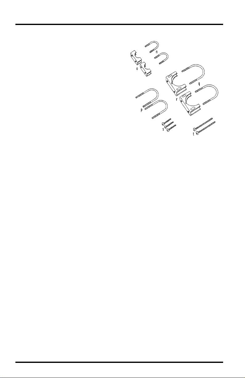
n.
Two 1/2” U-Bolts (for
anemometer arm)
o.
Two 1/2” Saddles
Two 1-1/2” U-Bolts (for
p.
pipe with outside diameter
between 1” and 1-1/4”
(25 mm and 31 mm)
q.
Two 2-1/4” U-Bolts (for
pipe with outside diameter
between 1-1/2” and 2-3/8”
(38 mm and 60 mm)
r.
Two 2-1/4” Saddles
s.
Three #8-32 x 3/4”
(19 mm) Screws
Two #8-32 x 2 -1/2”
t.
(64 mm) Screws
T
A
OOLS
In addition to the components listed above, you will need some of the following tools and materials. Please be sure you have everything you need before
beginning the installation.
SSEMBLING
The assembly of the sensor arm involves attaching the mounting bracket and
then attaching all desired sensors. Instructions for attaching sensors (other than
the anemometer) to the Sensor Mounting Arm are contained in the manual for
that sensor or for the accessory which allows that sensor to be attached (such as
the Radiation Shield or the Rain Collector Shelf). The Sensor Mounting Arm
includes provisions for attaching the following sensors:
M
AND
✦
✦
✦
✦
✦
✦
✦
✦
ATERIALS
Medium Phillips Screwdriver
Wrench or Pliers
11/32” (9 mm) Nut Driver or Socket Wrench
If mounting the anemometer on the same side as the Radiation Shield.
THE
S
Anemometer
External Temperature Sensor, External Temperature/Humidity Sensor, or Stainless
Steel Temperature Probe (with Radiation Shield or Solar-Fan-Aspirated Radiation
Shield)
Rain Collector (with Rain Collector Shelf)
UV Sensor (with or without Tilting Mechanism)
Solar Radiation Sensor (with or without Tilting Mechanism)
N
ENSOR
EEDED
OUNTING
M
A
RM
Page 2 Sensor Mounting Arm
Page 3
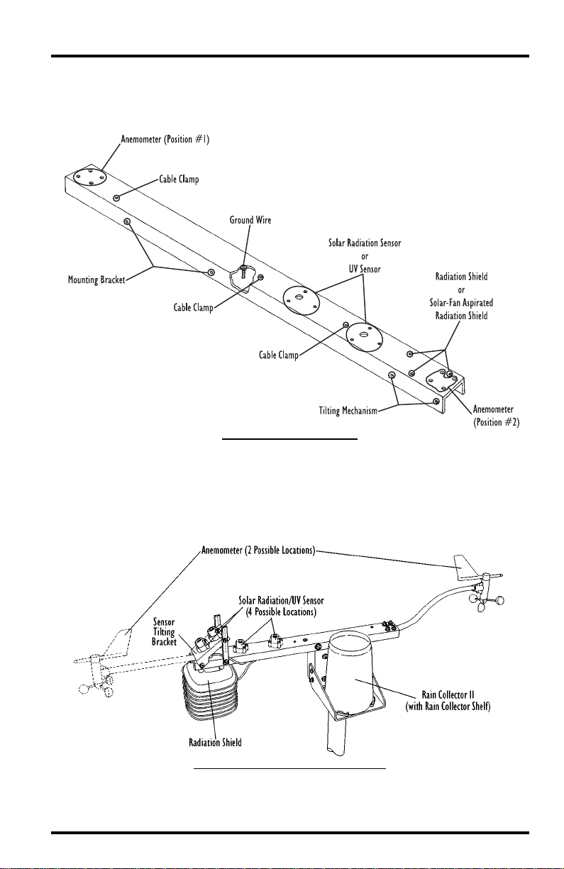
The Sensor Arm
The illustration below shows the sensor arm and indicates which holes are
used by the various sensors, brackets, and accessories.
S
A
H
RM
OLE
A
SSIGNMENTS
ENSOR
Typical Sensor Mounting Arm Installation
The illustration below shows a typical Sensor Mounting Arm installation
with all possible sensors attached to the sensor arm.
T
S
YPICAL
ENSOR
M
OUNTING
A
RM
I
NSTALLATION
Assembling the Sensor Mounting Arm Page 3
Page 4
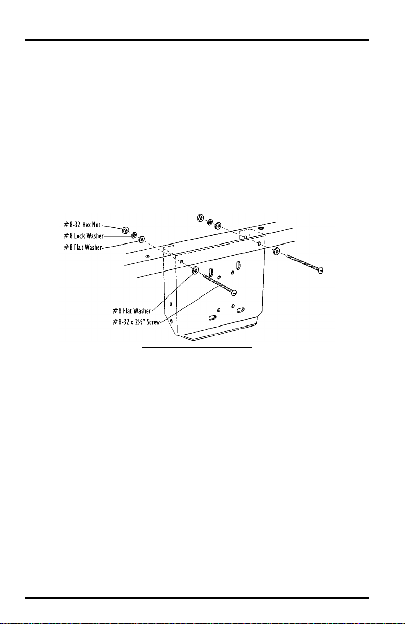
TTACHING
A
In order to attach the mounting bracket to the sensor arm, you will need the
sensor arm, mounting bracket, two #8-32 x 2-1/2” screws, four #8 flat washers,
two #8 split lock washers, and two #8-32 hex nuts.
1. Place one #8 flat washer over the end of each of the #8-32 x 2-1/2” screws.
2. Position the mounting bracket so the holes in the mounting bracket line up with the
3. Slide each of the #8-32 x 2-1/2” screws (with washer) through the holes on the sensor
4. Secure the mounting bracket to the sensor arm using a #8 flat washer, #8 split lock
THE
appropriate holes on the sensor arm.
arm and the mounting bracket.
washer, and a #8-32 hex nut on each screw end.
Tighten until the mounting bracket is securely fastened to the sensor arm.
OUNTING
M
A
TTACHING
RACKET
B
THE
M
OUNTING
B
RACKET
Page 4 Sensor Mounting Arm
Page 5
TTACHING
A
You may mount the anemometer on either side of the sensor arm. The preferred mounting location for the anemometer is on the end closest to the
mounting bracket. However, if you have an anemometer with a straight arm
and a Rain Collector attached to the Sensor Mounting Arm, the Rain Collector
might create obstruction problems which result in inaccurate wind speed and
direction readings. In this case (and only in this case), you may want to mount
the anemometer on the end farthest from the mounting bracket.
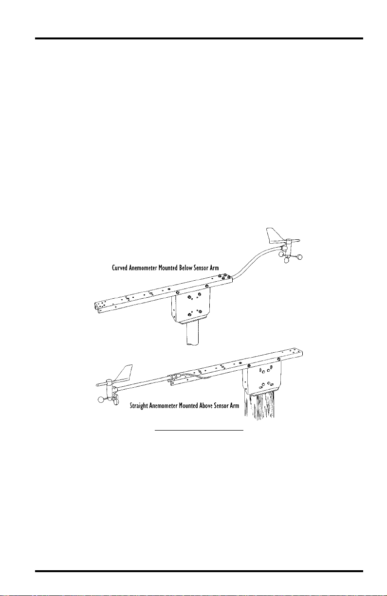
In general, you should mount the anemometer below the sensor arm, following
the instructions in “Attaching the Anemometer Below the Sensor Arm (Preferred)” on page 6. If, however, you need to mount the anemometer arm on the
end farthest from the mounting bracket
mounted on that side as well, attach the anemometer above the sensor arm, following the instructions in “Attaching the Anemometer Above the Radiation
Shield” on page 9.
THE
NEMOMETER
A
and
you have a radiation shield
T
A
YPICAL
NEMOMETER
Attaching the Anemometer Page 5
M
OUNTS
Page 6

Attaching the Anemometer Below the Sensor Arm (Preferred)
To attach the anemometer below the sensor arm, you will need the anemometer, sensor arm, two 1/2” U-bolts, two 1/2” saddles, four 1/4” flat washers,
four 1/4” split lock washers, four 1/4” hex nuts, one cable clamp, one #8-32 x
3/4” screw, one #8 flat washer, and one #8-32 hex nut.
A
NEMOMETER
A
TTACHED
B
ELOW
S
ENSOR
A
RM
1. If necessary, disconnect the anemometer from your weather station.
Your weather station manual contains instructions for connecting the two.
Simply reverse the directions to disconnect them.
2. If necessary, disconnect the anemometer arm from the anemometer base.
Your weather station manual contains instructions for connecting the two.
Simply reverse the directions to disconnect them.
3. Place one of the 1/2” U-bolts over the anemometer arm.
4. Slide one of the saddles over the end of the U-bolt so the anemometer arm is contained in the circle created by the U-bolt and the saddle.
P
LACE
U-B
OLT
AND
S
ADDLE
ON
A
NEMOMETER
A
RM
5. Repeat this process for the other 1/2” U-bolt and saddle.
Page 6 Sensor Mounting Arm
Page 7

6. Slide the ends of the U-bolts into the appropriate holes at the end of the sensor arm
nearest the mounting bracket.
S
U-B
OLTS
INTO
H
OLES
LIDE
7. Secure the U-bolts and anemometer arm in place using a 1/4” flat washer, 1/4” split
lock washer and 1/4” hex nut on each of the U-bolt ends.
Tighten the hex nuts with your hand so the arm is gently held in place. Do
not tighten fully until instructed to do so later on.
A
U-B
TTACH
THE
OLTS
AND
A
NEMOMETER
A
RM
Attaching the Anemometer Page 7
Page 8

8. Slide the anemometer arm backwards/forwards until the end of the anemometer arm
extends just 1/2” (13 mm) past the second U-bolt/saddle.
P
OSITION
A
NEMOMETER
A
RM
9. Once the anemometer arm is correctly positioned, tighten the hex nuts.
In order to keep the anemometer arm steady in high winds, tighten the hex
nuts until you notice the anemometer arm just begin to buckle underneath
the U-Bolt.
10.Place a cable clamp around the anemometer cable.
11. Slide a #8-32 x 3/4”screw down through the indicated hole on the sensor arm.
A
TTACH THE CABLE CLAMP
12. Slide the hole in the cable clamp over the end of the #8-32 x 3/4” screw.
13. Secure the cable clamp and cable in place using an #8 flat washer and an #8-32 hex
nut.
Tighten the hex nut until the cable is held snugly within the cable clamp.
Page 8 Sensor Mounting Arm
Page 9

Attaching the Anemometer Above the Radiation Shield
To attach the anemometer above the sensor arm, you will need the anemometer, sensor arm, two 1/2” U-bolts, two 1/2” saddles, four 1/4” flat washers,
four 1/4” split lock washers, four 1/4” hex nuts, one cable clamp, one #8-32 x
3/4” screw, one #8 flat washer, and one #8-32 hex nut.
A
NEMOMETER ATTACHED ABOVE SENSOR ARM
1. If necessary, remove the Radiation Shield from the sensor arm.
You cannot mount the anemometer above the Radiation Shield if the radiation shield has already been attached to the sensor arm.
2. If necessary, disconnect the anemometer from your weather station.
Your weather station manual contains instructions for connecting the two.
Simply reverse the directions to disconnect them.
3. If necessary, disconnect the anemometer arm from the anemometer base.
Your weather station manual contains instructions for connecting the two.
Simply reverse the directions to disconnect them.
4. Place one of the 1/2” U-bolts over the anemometer arm.
5. Slide one of the saddles over the end of the U-bolt so the anemometer arm is con-
tained in the circle created by the U-bolt and the saddle.
P
LACE
U-B
OLT AND
S
ADDLE ON ANEMOMETER ARM
6. Repeat this process for the other 1/2” (13 mm) U-bolt and saddle.
Attaching the Anemometer Page 9
Page 10

7. Position the U-bolts/saddles on top of the sensor arm on the side farthest from the
mounting bracket so the ends of the U-bolts drop into the appropriate holes.
S
LIDE
U-B
OLTS INTO
HOLES
8. While holding the U-bolts in place, turn the sensor arm over so the protruding ends
of the U-bolts are visible.
9. Secure the U-bolts and anemometer arm in place using a 1/4” flat washer, 1/4” split
lock washer and 1/4” hex nut on each of the ends of the U-bolts.
Tighten the hex nuts with your hand so the arm is gently held in place. Do
not tighten fully until instructed to later on.
ATTACH THE U-BOLTS AND ANEMOMETER ARM
Page 10 Sensor Mounting Arm
Page 11

10. Slide the anemometer arm backwards/forwards until the end of the anemometer arm
extends just 1/2” past the second U-bolt/saddle.
POSITION ANEMOMETER ARM
11. Once the anemometer arm is correctly positioned, tighten the hex nuts.
In order to keep the anemometer arm steady in high winds, tighten the hex
nuts until you notice the anemometer arm just begin to buckle underneath
the U-Bolt.
12. Place a cable clamp around the anemometer cable.
13. Slide a #8-32 x 3/4”screw down through the indicated hole on the sensor arm.
ATTACH THE CABLE CLAMP
14. Run the anemometer cable underneath the sensor arm and slide the hole in the cable
clamp over the end of the #8-32 x 3/4” screw.
Attaching the Anemometer Page 11
Page 12

15. Secure the cable clamp and cable in place using an #8 flat washer and an #8-32 hex
nut.
Tighten the hex nut until the cable is held snugly within the cable clamp.
Note:When you attach (or reattach) the Radiation Shield beneath the anemometer, you will find
that one of the Radiation Shield’s mounting screws is between the U-bolts/saddle, and will be
difficult to access. You will need a nut driver or socket wrench in order to tighten this nut.
MOUNTING THE SENSOR MOUNTING ARM
You may mount the sensor arm on a wooden post, onto a small pipe with an
outside diameter between 1” and 1-1/4“ (25 mm and 31 mm), or onto a large
pipe with an outside diameter between 1-1/2” and 2-3/8” (38 mm and 60 mm).
Mounting the Sensor Mounting Arm on a Wooden Post
T o attach the Sensor Mounting Arm to a wooden post, you will need the sensor
arm assembly (with mounting bracket and sensors attached), four 1/4” x 1-1/2”
lag screws, and four 1/4” flat washers.
Note:The Sensor Mounting Arm must be mounted at the top of the post.
1. Position the back of the mounting bracket against the post.
2. Secure the mounting bracket to the post using the four 1/4” x 1-1/2” lag screws and the
four 1/4” flat washers.
Tighten until the mounting bracket and sensor arm are held securely in
place.
MOUNTING ON A WOODEN POST
Page 12 Sensor Mounting Arm
Page 13

Mounting the Sensor Mounting Arm on a Small Pipe
Follow the instructions below to mount the Sensor Mounting Arm on a pipe
with an outside diameter between 1” and 1-1/4” (25 mm and 31 mm). To
attach the sensor arm to a small pipe, you will need the sensor arm assembly
(with mounting bracket and sensors attached), two 1-1/2” U-bolts, four 1/4”
flat washers, four 1/4” lock washers, and four 1/4” hex nuts.
Note:When mounting on a small pipe, the Sensor Mounting Arm must be mounted at the top of the
pipe.
1. Position the mounting bracket (with sensor arm) against the pipe.
2. Slide the ends of one of the 1-1/2” U-bolts (so that the U-bolt wraps around the pipe)
into the holes on the mounting bracket.
3. Secure the U-bolts in place using a 1/4” flat washer, 1/4” lock washer, and a 1/4” hex
nut.
Tighten the hex nuts securely.
4. Repeat the procedure above for the other U-bolt.
MOUNTING ON A SMALL PIPE
Mounting the Sensor Mounting Arm Page 13
Page 14

Mounting the Sensor Mounting Arm on a Large Pipe
Follow the instructions below to mount the Sensor Mounting Arm on a pipe
with an outside diameter between 1-1/2” and 2-3/8” (38 mm and 60 mm). To
attach to a large pipe, you will need the sensor arm assembly (with mounting
bracket and sensors attached), two 2-1/4” U-bolts, two 2-1/4” saddles, four 5/
16” flat washers, four 5/16” lock washers, and four 5/16” hex nuts.
1. Wrap one of the 2-1/4” U-bolts around the pipe and hold it in place.
2. Slide one of the 2-1/4” saddles over the ends of the U-bolt so that it wraps around the
pipe as well.
U-BOLTS AND SADDLES ON PIPE
3. Repeat the steps above for the other U-bolt and saddle.
4. Slide the ends of the U-bolts into the holes on the mounting bracket.
5. Secure the U-bolt in place using a 5/16” flat washer, 5/16” lock washer, and a 5/16” hex
nut.
Tighten the hex nuts securely.
Page 14 Sensor Mounting Arm
Page 15

GROUNDING THE SENSOR MOUNTING ARM
We strongly recommend that you ground the sensor arm. You will need the
16.5’ (5 m) ground wire, one #8 split lock washer, and one #8-32 hex nut.
1. Slip the ring at the end of the 16.5’ (5 m) ground wire over the lug on the underside of
the sensor arm.
2. Secure the ground wire to the lug using a #8 split lock washer and a #8-32 hex nut.
SECURE GROUND WIRE TO SENSOR ARM
3. Connect the other end of the ground wire to a suitable earth ground (grounded metal
cold water pipe or ground rod driven into the earth).
SAFETY AND BUILDING CODES
When installing the Sensor Mounting Arm, a 2” (5 cm) pipe should be adequate for general homeowner’s backyard or open-field agricultural locations
for a mounting height of 6 to 8 feet (2 to 2.5 m) provided that low wind-loading
conditions apply and the pipe is anchored to a suitable foundation. (If you are
unsure, consult a qualified professional for national and local codes.)
Regardless of the mounting location, local building codes must be followed. If
you want to mount onto a taller mast, a building, or any location where high
wind or seismic loads might be encountered, seek professional help from a
structural engineer or local contractor. Remember always to use common
sense.
When installing the Sensor Mounting Arm and sensors, always watch for overhead power lines. Electric shock, death, or damage to the sensitive electronics
could result if you or the sensors come in contact with electric power lines.
Grounding the Sensor Mounting Arm Page 15
Page 16

MAINTAINING THE SENSOR MOUNTING ARM
You should check the tightness of the various screws and U-bolts periodically.
Pay particular attention to the U-bolts holding the anemometer arm in place.
TECHNICAL SUPPORT
Before calling Technical Support (1-510-732-7814), carefully check this instruction manual for the answer to your question.
Product Number: 7702
Davis Instruments Part Number: 7395-091
Sensor Mounting Arm
Rev. C Manual (7/7/99)
DI:Weather:Accessories:Sensor Mounting Arm
This product complies with the essential protection requirements of the EC EMC Directive 89/336/EC.
© Davis Instruments Corp. 1997. All rights reserved.
 Loading...