

Davis 7470 Installation Manual
EZ-M
NSTALLATION MANUAL FOR GROWEATHER
I
NERGY ENVIROMONITOR
E
EALTH ENVIROMONITOR
H
This manual describes how to install the EZ-Mount Advanced Station.
Separate manuals included with the station cover the operation of the console
and sensors.
The EZ-Mount Advanced Stations are the “EZ” installation versions of the
GroWeather, Energy EnviroMonitor and Health EnviroMonitor stations. In
addition to the normal EZ-sensor suite, the advanced stations feature an
Sensor Arm
station).
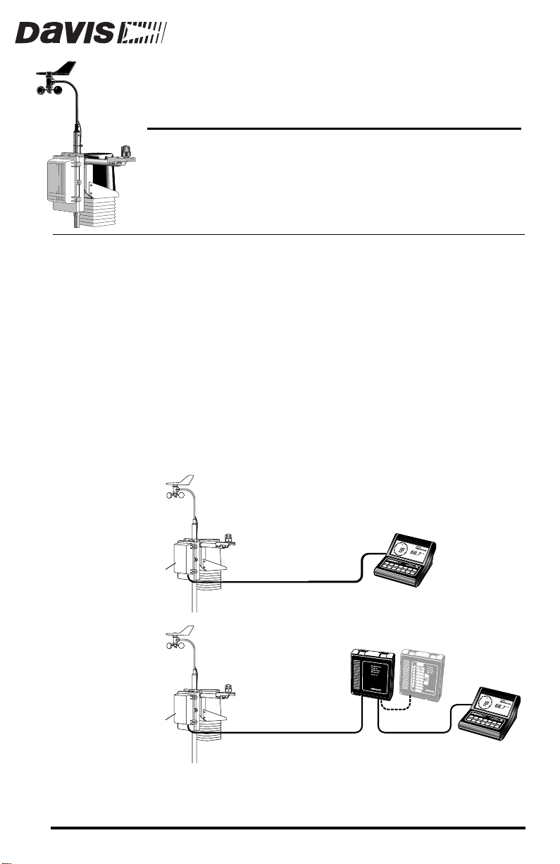
There are two installation options for the EZ-Mount Advanced Stations:
dard
frequency interference, electrostatic discharges, and voltage surges by providing 100 feet of
Cable Adapter Module) with its own grounding wire, and a 25 foot (7.5 m)
cable to connect the ICAM to the console.
for measuring Solar Radiation and/or UV (depending on the
and
industrial
shielded
Sensor Array
OUNT
. The industrial option offers greater protection from radio
cable, an extra grounding wire, an ICAM (Interface
STANDARD INSTALLATION
A
DVANCED STATION
®
AND
S
YSTEMS
®
®
EZ-
stan-
,
Standard Sensor Interface
Module (SIM) inside Field Case
Sensor Array
Industrial Sensor Interface
Module (SIM) inside Field Case
Additional products—such as the Alarm Output Module (AOM), Mounting
Tripod, EZ-Solar Power Kit, WeatherLink
tioned here but are not required (contact Davis for more information).
Product # 7450EZ, 7455EZ, 7460EZ, 7465EZ, 7470EZ, 7475EZ (EU, UK, M)
100' Standard
8-Conductor Cable
INDUSTRIAL INSTALLATION
Interface Cable
Adapter Module
(ICAM)
100' Shielded
8-Conductor Cable
®
, and Grounding Kit—are men-
Console
25' Standard
8-Conductor Cable
Optional Alarm
Output Module
(AOM)
Console
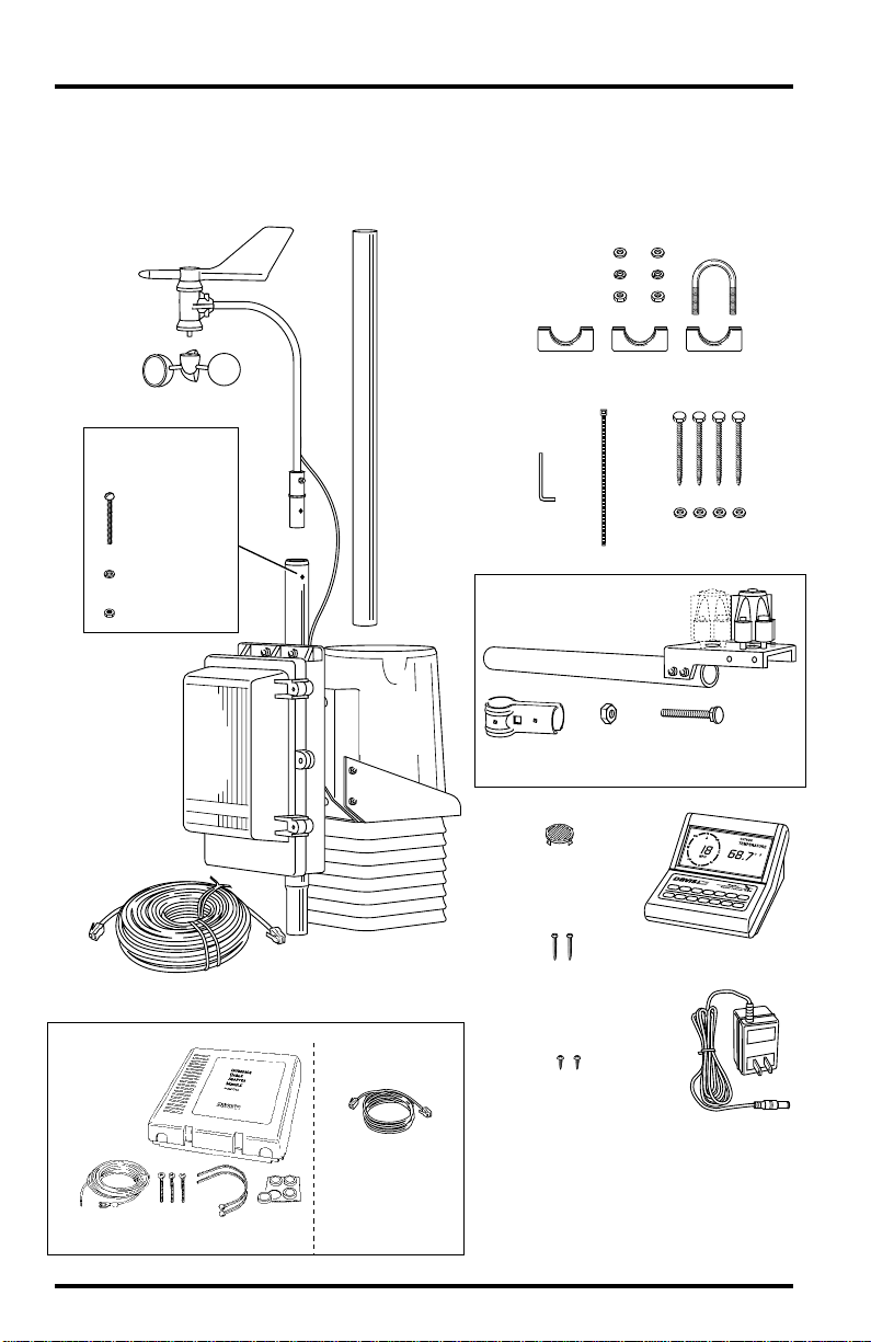
OMPONENTS
C
The EZ-Mount Advanced Weather Station includes the following components. Please make sure you have everything you need before beginning.
Anemometer
Wind Cups
This hardware
comes installed
on Sensor Array:
#8 x 1-1/2"
Pan HeadScrew
#8 Lock Washer
#8 Hex Nut
Sensor Array
16.5' (5m) Ground Wire(s)
(Not Shown)
Extension
Tube
Rain
Collector
Cone
5/16" Flat Washers
5/16" Lock Washers
5/16" Hex Nuts
1-1/8"
Saddles
Cable
Tie
Allen
Wrench
EZ-Sensor Arm
Brace Clamp
Debris Screen
(place inside
Rain Collector Cone
after installation)
5/16"
Hex Nut
5/16" x 1-1/2"
U-Bolt
5/16" x 3"
Lag Screws
5/16"
Flat Washers
5/16" x 2"
Carriage Bolt
100' (30 m) 8-Conductor Cable, Standard
(Industrial Not Shown)
Additional Components for INDUSTRIAL Installations Only
Interface
Cable
Adapter
Module
ICAM Kit
(ICAM)
16.5' (5m)
Ground Wire
Page 2 EZ-Mount Advanced Station
#6x1"
(25mm)
Screws
Cable
Ties
Adhesive
Pads
8-Conductor Cable,
Standard,
for ICAM to Console,
25' (7.5m)
#8 x 3/4"
Pan Head Screws
(for mounting Console
on wall)
#6 x 1/4"
Pan Head Screws
(for mounting Console
on Field Case door)
Weather Station Console
Power Adapter

OOLS
T
AND
ATERIALS
M
N
EEDED
In addition to the components listed on page 2, you may need some of the following tools and materials.
Flat-Bladed Screwdriver
✦
Phillips Screwdriver
✦
✦
Adjustable Wrench
Wire Cutter or Scissors
✦
Wire Stripper or Knife (Industrial Installation Only)
✦
✦
Electrical Tape
Cable Clips or Weather-Resistant Cable Ties (with ability to be mounted)
✦
Hammer
✦
NSTALLATION
I
S
TEPS
This manual takes you through the step-by-step process of installing your
weather station. These steps are indicated below, along with their page numbers for easy reference:
Assemble and test the station, page 4
✦
✦
Detach the extension tube, page 4
Attach the anemometer, page 4
✦
✦
Attach the wind cups, page 4
Snip the cable tie in the rain collector, page 5
✦
✦
Apply power to the console, page 5
✦
Attach the EZ-Sensor Arm, page 6
Connect sensor array to console, page 8
✦
✦
Check that the console and sensors are working properly, page 8
Re-attach rain collector cone and unplug sensor array (or ICAM)
✦
cable from console, page 8
✦
Install the station, page 9
Choose locations for the sensor array and console, page 9
✦
✦
Mount, secure, and ground the sensor array, pages 10 & 11
Run sensor array cable (or ICAM cable) to console, page 11
✦
✦
Industrial stations only : mount the ICAM, page 11
Mount the console, page 14
✦
If, once installed, you encounter any problems with the station, please refer to
the troubleshooting guide on page 14 or call our technical support line (510732-7814) for assistance.
Tools and Materials Needed Page 3
ETTING
G
TARTED
S
Follow the steps below to install your station. At various stages of this installation, you will be advised to test the system to ensure proper functioning.
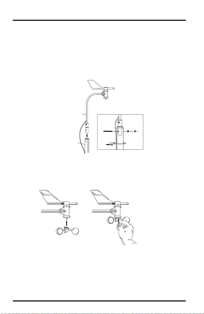
1. Detach and remove the extension tube from the support tube by cutting the two black
cable ties.
2. Attach the anemometer arm to the support tube as shown below. Make sure that the
anemometer is positioned over the white field case and NOT over the black rain collector cone.
Anemometer
Anemometer Arm
Lock
Washer
Cable Tie
Hex
Nut
Anemometer
Cable
Support Tube
#12 x 1-1/2"
Screw
3. Attach the wind cups to the anemometer.
Push the wind cups onto the shaft as far as they will go, then tighten the set
screw. The cups should drop slightly and into the ideal position automatically. Spin the wind cups. If they do not spin freely, loosen the set screw and
lower the cups slightly. Repeat until the wind cups spin freely.
a. Push cups onto
stainless steel shaft
Page 4 EZ-Mount Advanced Station
b. Tighten set screw
with allen wrench
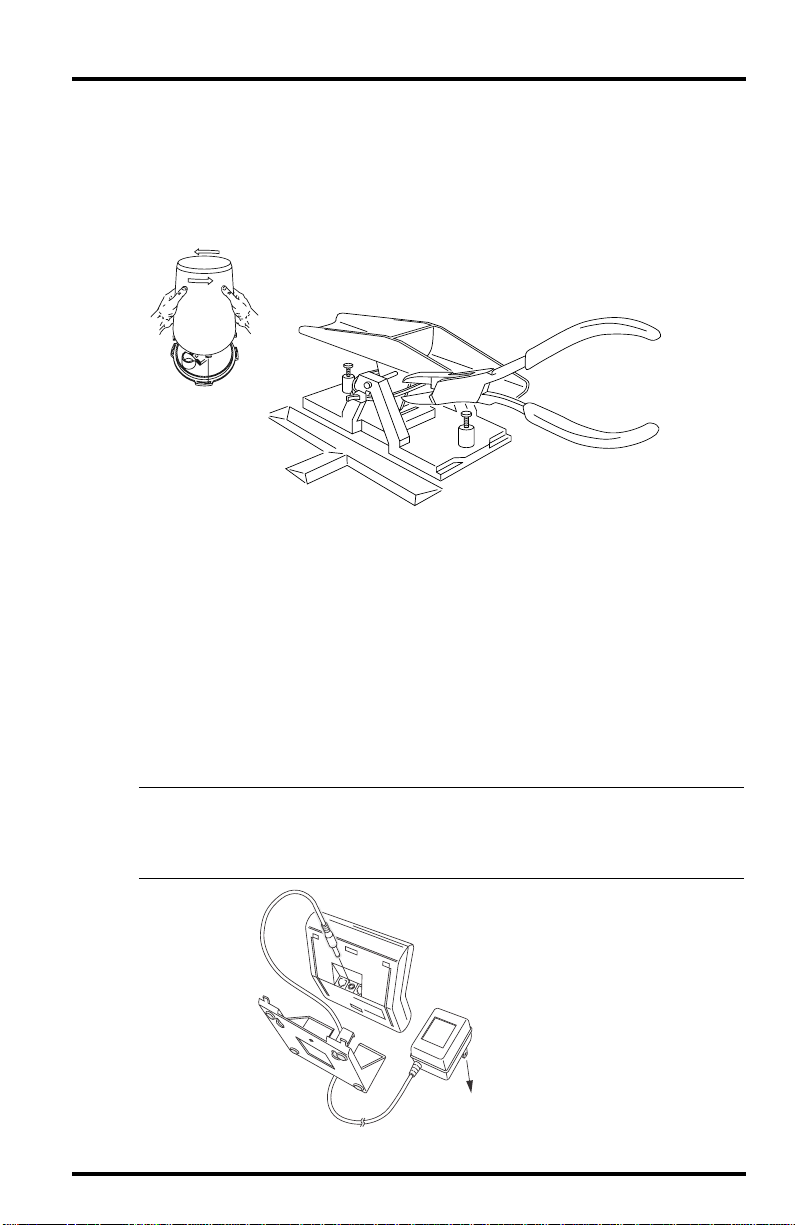
4. Detach the rain collector cone and snip the cable tie.
Detach the black rain collector cone from its base by rotating the cone
counter-clockwise until its latches line up with the latch openings in the base
and then raise the cone off. (The cone may be tightly attached to the base the
first time.) C
arefully cut and remove the black cable tie which holds the bucket in
place during shipping.
Twist off the rain collector cone.
Snip the black cable tie.
Do not re-attach the rain collector cone at this point; you will need to test the
tipping bucket before you complete the installation.
5. Apply power to the station console.
To power up the console, first remove the console’s mounting base by pressing down on the large tab between the two oblong holes on the base’s
underside and pulling the base free. Plug the power adapter into the center
“Power” slot, as shown below, and then plug the other end into a 110 VAC
outlet. Once power is applied, the console should beep twice within 10 seconds if the console is working properly. (If you have the optional WeatherLink installed, the console should beep three times within 20 seconds.) The
readings will appear dashed out until you connect the sensors.
Note: If you are going to use a battery as backup, make sure that you plug in the AC power before
installing the battery . Powering up the console with the battery alone may cause the console
to lock up due to insufficient power. (Do NOT use a backup battery if you use the optional
EZ-Solar Power Kit.)
Console
Power Adapter
Base
AC Power
Outlet
Getting Started Page 5
 Loading...