

Page 1
UV and Solar Radiation Sensors
For Vantage Pro® and Vantage Pro2™ Weather Stations
The Davis Instruments UV Sensor is a precision instrument that detects ultraviolet (UV) radiation at wavelengths of 290 to 390 nanometers. The spectral
response is closely matched to the Erythema Action
Spectrum, defined by McKinlay and Diffey (1987) and
internationally recognized as the radiation that is most
responsible for causing redness of the human skin.
The Davis Instruments Solar Radiation Sensor is a precision instrument that detects radiation at wavelengths
of 300 to 1100 nanometers. The spectral response of
the silicon photodiode detector is a good match to the
spectrum of solar irradiance.
Typically, users install both the Solar Radiation Sensor and the Davis UV Sensor. However, users may install only one of these sensors. Unless otherwise noted, instructions
in this manual apply to both sensors.
Individual specifications for each sensor are listed on the Davis Website at
http://www.davisnet.com/support/weather/ under the spec sheets link.
Note: Sunburn is not the only consequence of exposure to UV radiatio n. Skin cancer s, cat a ract s, and d am-
age to the immune system are caused by UV radiation. Exposure to UV radiation should be minimized.
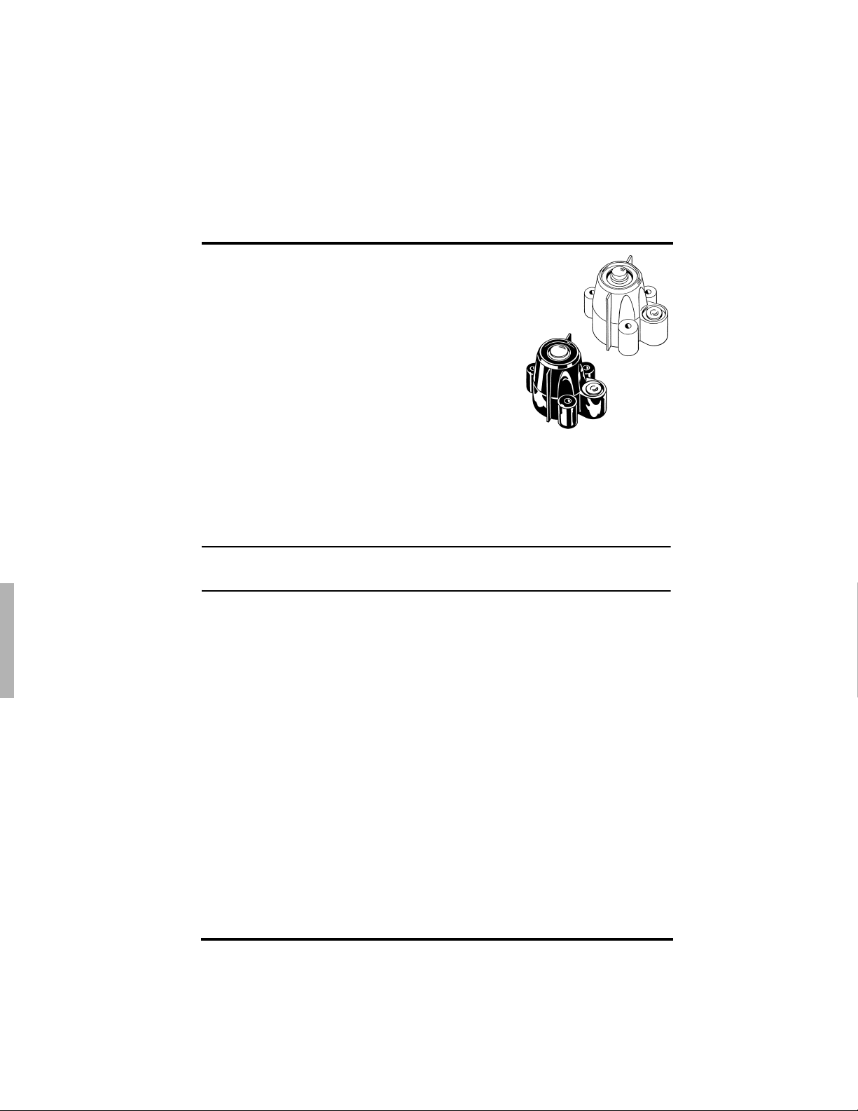
The UV Sensor is comprised of the following components:
Shield—The outer shell shields the sensor body from thermal radiation and provides a
path for convection cooling of the body , min imizing heating of the sensor interior. It
provides a cutoff ring for cosine response, a level indicator, and fins to aid in aligning
the sensor with the sun’s rays.
Sensor Body—Houses the following components:
• Diffuser—Provides, with gasket, a weather-tight seal and excellent cosine response.
• Filter—Provides the Erythema Action spectral response. Encased in multiple hard-
oxide coatings, the filter is stable in the presence of heat and humidity.
• Detector—Contains a semiconductor diode that, with the filter, responds to radia-
tion only in the specified wavelengths.
• Amplifier—Converts the detector current into a 0 to +2.5V signal.
The Solar Radiation Sensor is comprised of the following components:
Shield —Serves the same role as in the UV Sensor.
Sensor Body —Composed of a shield, the same as that in the UV Sensor; and a sensor
body, which contains a precision machined dif fuser giving excellent co sine response; a
hermetically sealed silicon photodiode; and an amplifier.
Products #6450 and #6490
Page 2
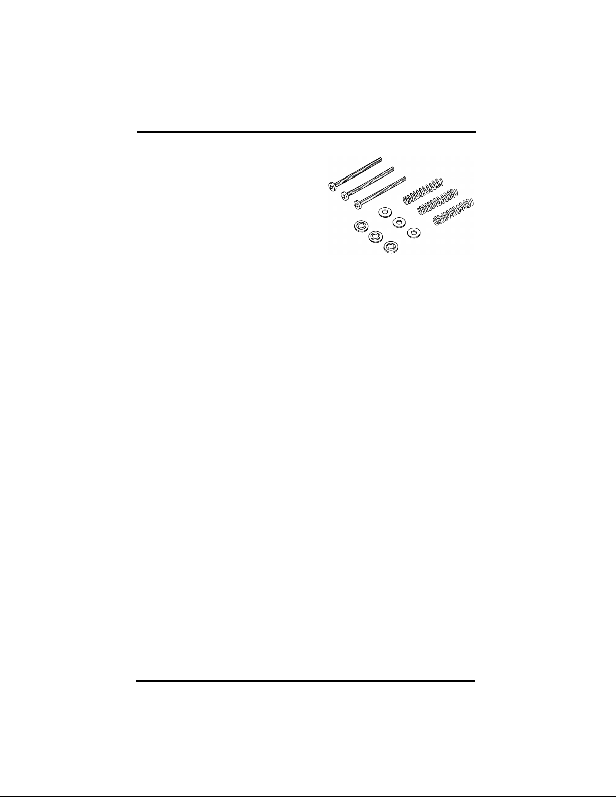
Mounting Hardware
Please make sure you have all components
listed below before continuing.
• Shield
• Body with cable attached
• Three #6-32 x 1-1/2" (38 mm) machine
screws
• Three springs
• Three #6 flat washers
• Three #6 screw retainers
Tools and Materials Needed
To install your new sensor, you will need a medium Phillips screwdriver.
Mounting the Sensors
Installation on the Sensor Mounting Shelf
The Solar Radiation and UV Sensors are designed to be mounted on the Sensor Mounting Shelf (Davis Instruments Product Number 6672). The Sensor Mounting Shelf is a
stand that attaches to your ISS and provides a mounting location for up to two sensors.
First mount the shelf on the ISS and then follow these instructions to mount a UV or
Solar Radiation Sensor on the shelf. The shelf has two mounting locations, one to hold
a UV sensor and a the other for a Solar Radiation Sensor. Because they are identical, it
doesn’t matter which location you use first.
Testing the Sensor
On the Integrated Sensor Suite (ISS), the connections for the Solar Radiation and UV
sensors are inside the Sensor Interface Module (SIM) Box. Before permanently installing your new sensor, Davis Instruments recommends that you test it first. To do this,
take your console with you out to your ISS, and follow the instructions below.
Accessing the SIM
To access the SIM on a Vantag e Pro2 station, open the SIM Box. See Opening the SIM
Box in the Vantage Pro2 ISS Installation Manual for more information. On earlier Van-
tage Pro stations, the SIM Box is located below the ISS Radiation Shield. For instructions on how to access the SIM Box on these stations, see Opening the SIM Box in the
Vantage Pro ISS Installation Instructions. On Fan Aspirated Vantage Pro and Vantage
Pro2 stations, the SIM is located in a separate housing. Again, consu lt your ISS instruction manual for detailed instructions on how to access your SIM.
1. Plug the sensor cable into the receptacle labeled “UV” on the SIM if it is a UV
sensor or into the receptacle labeled “SUN” if it is a Solar Radiation Sensor.
Hold the sensor body with the white diffuser pointed upward. Do not touch the diffuser. If you do, clean it after mounting using a cotton swab and ethyl alcohol. Do
not use rubbing alcohol.
Page 2
Page 3

2. On a Vantage Pro console, press UV to see the UV sensor reading if you are installing a UV sensor. If you are installing a Solar Radiation Sensor, press 2ND then
SOLAR to see the Solar Radiation reading.
On a Vantage Pro2 console, press 2ND then UV to see the UV sensor reading and
2ND then SOLAR to see the Solar Radiation Reading.
3. Shade the sensor with your hand. The value should drop. A zero is a possible reading; however, if you see dashes, wait a minute for a reading to come in. If you still
see no reading, reconnect the sensor cable to the ISS, ensuring it is in the proper
receptacle. If you still see no reading, contact Davis Technical Support (see Techni-
cal Support at the back of this manual).
4. Unplug the sensor cable from the SIM.
For permanent mounting, unplug the cable from the ISS
and follow the instructions below. The test procedure is
complete.
Securing the Sensor on the Shelf
1. Remove the rain collector cone from the ISS: turn it
counterclockwise until the latches allow you to lift it up
and off.
2. Place the sensor shield onto the sensor body as shown
here.
3. Route the sensor cable down through
one of the large holes in the mounting
shelf.
4. Place a flat washer over the end of each
screw and insert it through the shield
and body.
5. Place a spring over the end of each
screw and hold the springs in place
using a #6 screw retainer.
6. Secure the sensor to the mounting shelf
by driving the screws into the appropriate holes as shown.
7. Using the bubble level on the sensor as a
guide, adjust the sensor until it is level
by tightening or loosening the screws.
8. Repeat the above process to install an
additional sensor. Replace the rain collector cone when finished.
Note: Final leveling of the sensor(s) should be done with the ISS mounted in its operating location.
Routing the Sensor Cable
Route the sensor cable to the SIM Box and insert the cable jack into its appropriate
receptacle, marked SUN for a Solar Radiation Sensor or UV for a UV Sensor. Ensure
that the cables are free of crimps and are dressed so that they will not fray in the wind.
Page 3
Page 4

On Vantage Pro stations with a squared radiation shield, ensure that the cables run to
the SIM Box following the same path through the radiation housing as the rest of the
sensor cables. Consult your ISS Manual for instructions on how to do this.
On later Vantage Pro stations and Fan-Aspirated Vantage Pro stations, ensure that the
sensor cables run down through the holes near the base of the sensor mounting shelf
and through the grommet in the SIM Box that the other sensor cables run through.
On Vantage Pro2 stations, first run the cables down from the Sensor Mounting Self and
down through the holes near the base of the Sensor Mounting Shelf. Next, run the
cables through the space between the Rain Collector and the Radiation Shield, following the other sensor cables to the access port at the back of the SIM Box. Open the Sim
Box, remove the Foam Insert, and guide the cable through the access port. Insert the
cable jack into the proper receptacle and replace the Foam Insert, ensuri ng that the
Foam Insert fills all large voids in the access port.
Maintaining the Sensor
For the most accurate readings, clean the diffuser after mounting, and then periodically.
Use ethyl alcohol (not rubbing alcohol).
Due to the sensitivity of ultraviolet and solar radiation sensors, it is common practice
for manufacturers to recommend recalibration after a period of time. Here at Davis
Instruments, we have seen approximately 2% drift per year on the readings from these
sensors. For applications demanding higher accuracy, the sensors should be calibrated
once every year.
Sensor Troubleshooting
If encountering sensor problems, carefully check all cable connections from the sensor
to the console. Cable connections account for a large portion of the potential problems.
Connections should be firmly seated in the jacks and plugged in straight. Try jiggling
the cable while looking at the display. If a reading appears intermittently on the display
as you jiggle the cable, the connection is faulty.
Contacting Davis Technical Support
If you have any questions about the sensors or encounter problems installing the sensors, please contact Davis Technical support:
(510) 732-7814—Monday Through Friday, 7:00 a.m. to 5.30 p.m., Pacific Time.
(510) 670-0589—Fax to Technical Support.
Product Numbers: 6450 and 6490 Document Part Number: 07395.292
UV and Solar Radiation Sensor Installation Manual Rev. C (April 6, 2006)
Vantage Pro
© Davis Instruments Corp. 2006. All rights reserved.
Information in this document subject to change without notice.
This product complies with the essential protection requirements of the EC EMC Directive 89/336/EC.
Copyright © 2005 Davis Instruments Corp. All rights reserved.
®
and Vantage Pro2™ are trademarks of Davis Instruments Corp., Hayward, CA.
'LDEOR$YHQXH+D\ZDUG&$
)D[
(PDLOLQIR#GDYLVQHWFRPZZZGDYLVQHWFRP
 Loading...