

Davis 6385 Installation Manual
AN-ASPIRATED
F
IRELESS
W
EMPERATURE/HUMIDITY
T
S
TATION
I
NSTALLATION MANUAL
The Fan-Aspirated Wireless Temperature/Humidity Station, referred to in this
manual as the Aspirated Temp/Hum Station, combines fan aspiration and passive shielding to minimize the effects of solar radiation, increasing the accuracy
of temperature measurement. This instruction manual takes you step-by-step
through the process of installing and mounting your station.
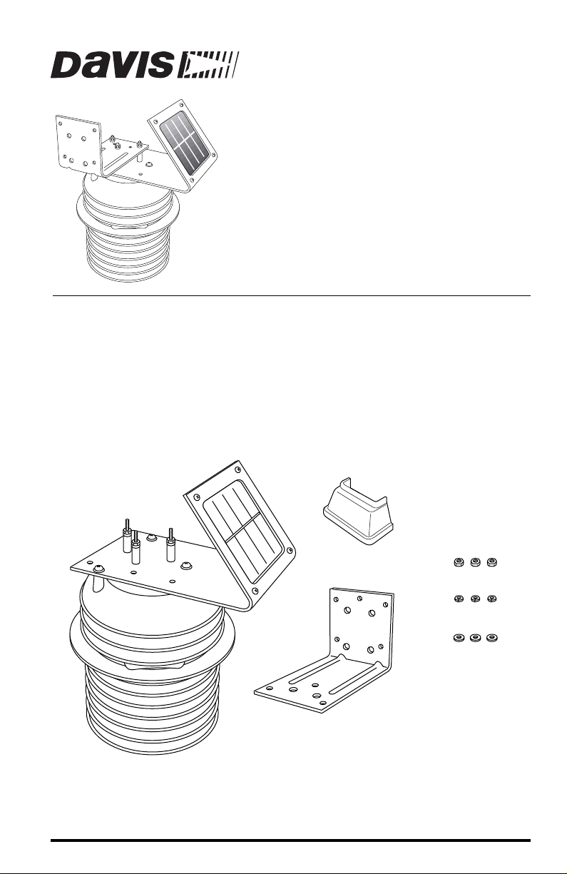
Components
The Aspirated Temp/Hum Station includes these items shown below and on
the next page:
Junction Board Cover
#8 Hex Nuts (3)
Fan-Aspirated Radiation Shield
Components, Part 1
#8 Lock Washers (3)
#8 Flat Washers (3)
Mounting Bracket
Product # 6385
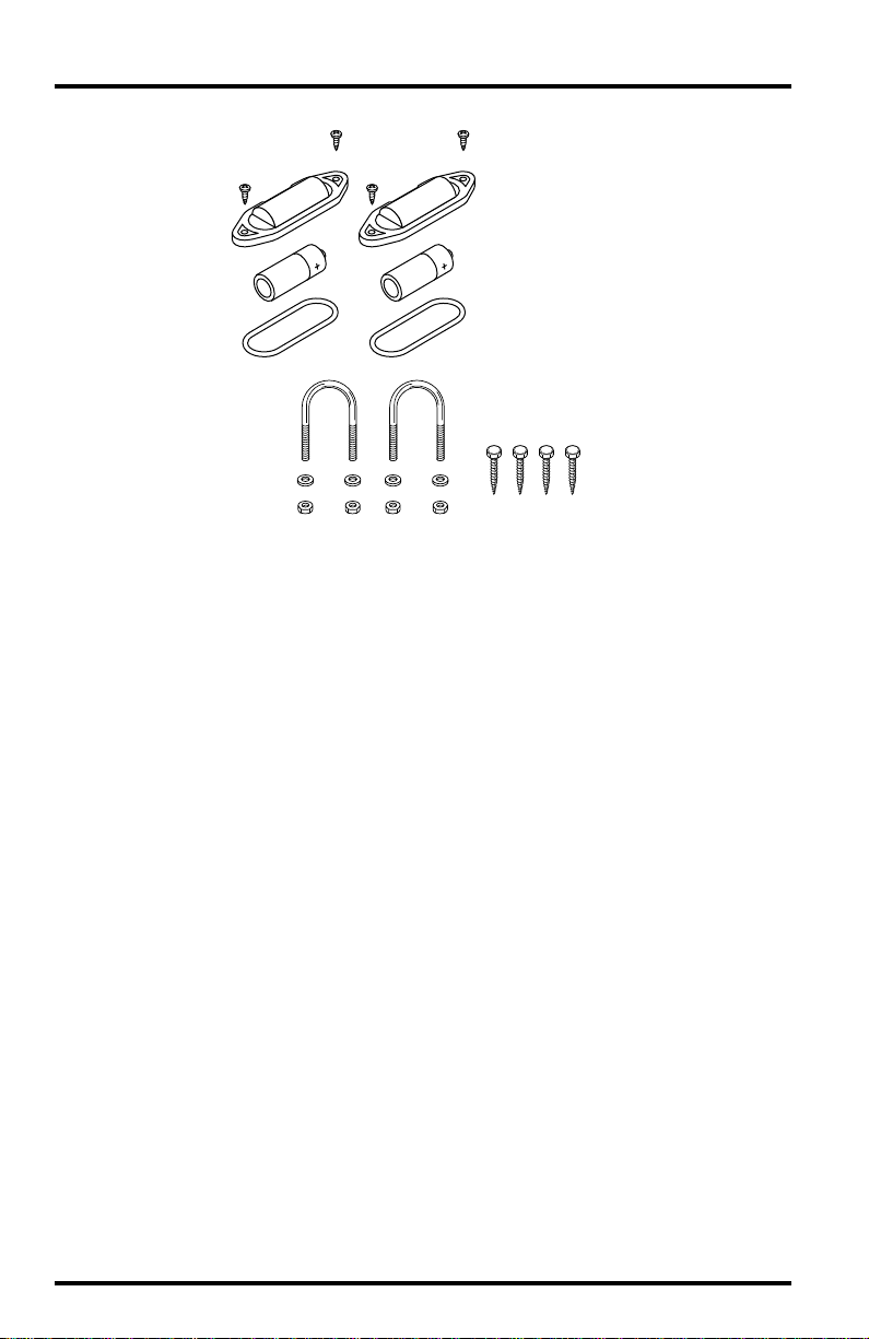
#4 Self-Threading
Screws (4)
Battery Covers (2)
1.2 Volt Nicad
Batteries (2)
O-Rings (2)
Supplied by customer
1-1/2" U-Bolts (2)
1/4" Flat Washers (4)
1/4" Hex-Nuts (4)
Components, Part 2
for wall or post mounting:
1/4" x 1-1/2"
Lag Screws (4)
Tools Needed
You may need the following tools to install your Aspirated Temp/Hum Station:
✦
A medium Phillips-Head screwdriver.
A small wrench or 3/8” (9 mm) nutdriver.
✦
Installation Steps
The Aspirated Temp/Hum Station comes pre-assembled. You will need to disassemble your station to prepare it for operation.
Here are the installation steps for your station:
1. Disassemble the station.
2. Install the Sensor Interface Module (SIM) batteries.
3. Configure the DavisTalk transmitter ID code.
4. Install the fan batteries.
5. Reassemble the station.
6. Choose a location for the station.
7. Mount the station.
Page 2 Wireless Temperature/Humidity Station
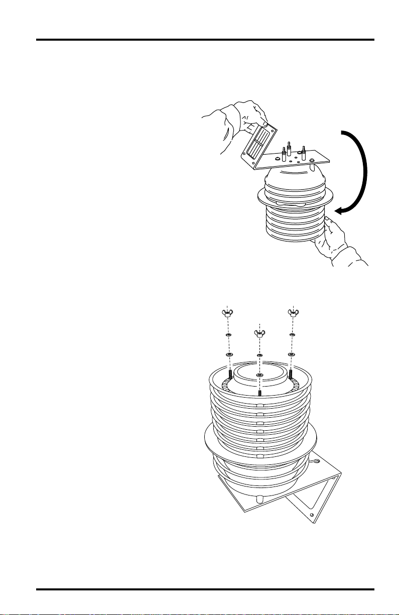
Disassembling the Station
Open up the station by separating the top and bottom parts as shown in the following illustrations.
1. Turn the station upside
down.
Hold plates
while inverting
Inverting the Aspirated Temp/Hum Station
2. Remove the three wing nuts,
lock washers and flat washers located on the underside
of the station.
3. T urn the station right-side up
with the mounting studs on
top.
#8 Wing Nuts
#8 Lock Washers
#8 Flat Washers
Removing the Wing Nuts
Installation Steps Page 3
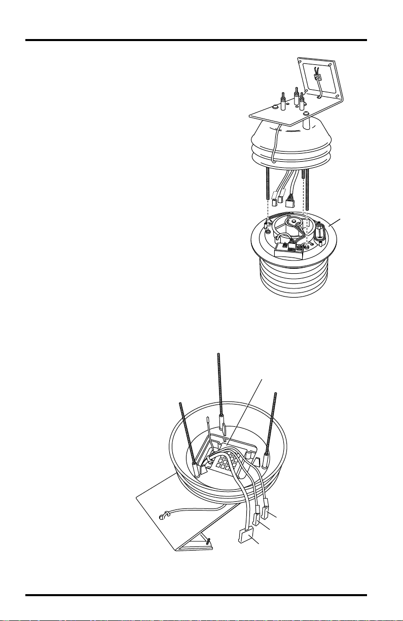
4. Lift off the upper section of the station to expose the fan plate in the
lower section.
Upper
Section
Aspirated
Radiation
Shield
S
I
S
M
O
L
Lower
Section
Separating the Radiation Shield
Installing the Sensor Interface Module (SIM) Battery:
1. Locate the SIM
inside the
upper section
of the station.
Sensor Interface
Module (SIM)
Fan Plate
S
O
L
S
I
M
Solar Panel Cable (+V SOL)
SIM Power Cable (+V SIM)
Sensor Interface Cable
Locating the Sensor Interface Module
Page 4 Wireless Temperature/Humidity Station
2. Insert the 3-volt lithium battery into the battery holder, matching the “+”
sign on the battery with the “+” sign on the SIM.
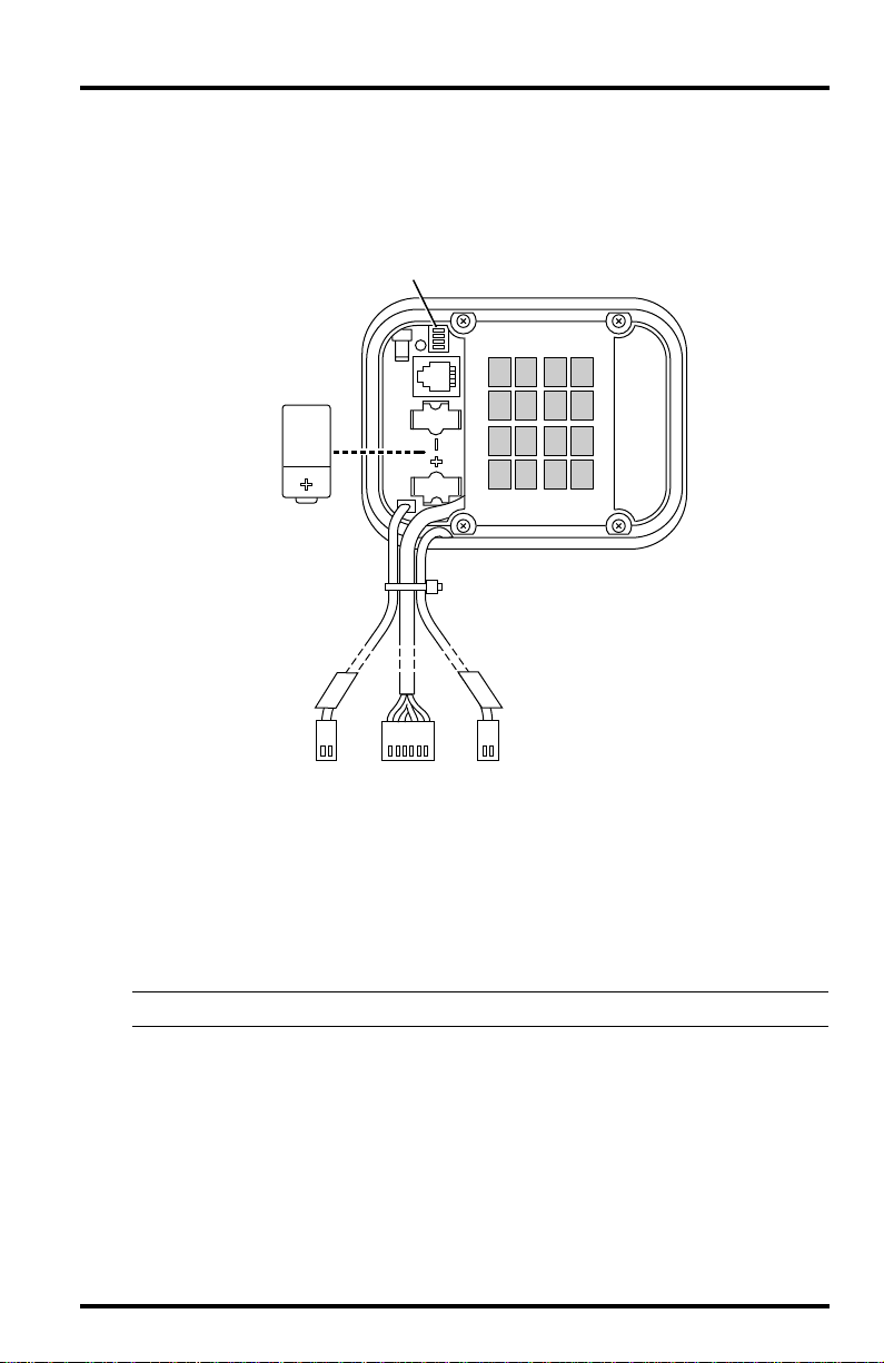
Consult this drawing to locate the transmitter ID switches. You will work
with them during the next installation step.
Transmitter
ID Switches
3-Volt
Lithium Battery
S
I
M
Sensor Interface
Cable
Sensor Interface Module on Temperature/Humidity Station
S
O
L
Solar Panel CableSIM Power Cable
Setting the DavisTalk Transmitter ID
Each wireless transmitting station must be set to one of eight DavisTalk transmitter IDs. Use the transmitter ID switches #1, 2 and 3 to set the station’s ID.
Switch #4 is only used for transmission testing.
Note: The transmitter and receiver communicate with each other only when both are set to the same ID.
The factory default transmitter ID is “1”. Looking at the table on the next page,
you can see that means the transmitter ID switches are in the OFF position when
each transmitting station leaves the factory.
Be sure to select a unique DavisTalk transmitter ID for your Aspirate
Temp/Hum station.
Use a ballpoint pen or paper clip to toggle DIP switches #1, 2, and 3.
tings for transmitter IDs 1 – 8 are shown in the following table:
The set-
Setting the DavisTalk Transmitter ID Page 5
 Loading...