

Davis 6361 Installation Manual
W
IRELESS
OIL
S
T
I
NSTALLATION MANUAL
M
EMPERATURE STATION
OISTURE
/
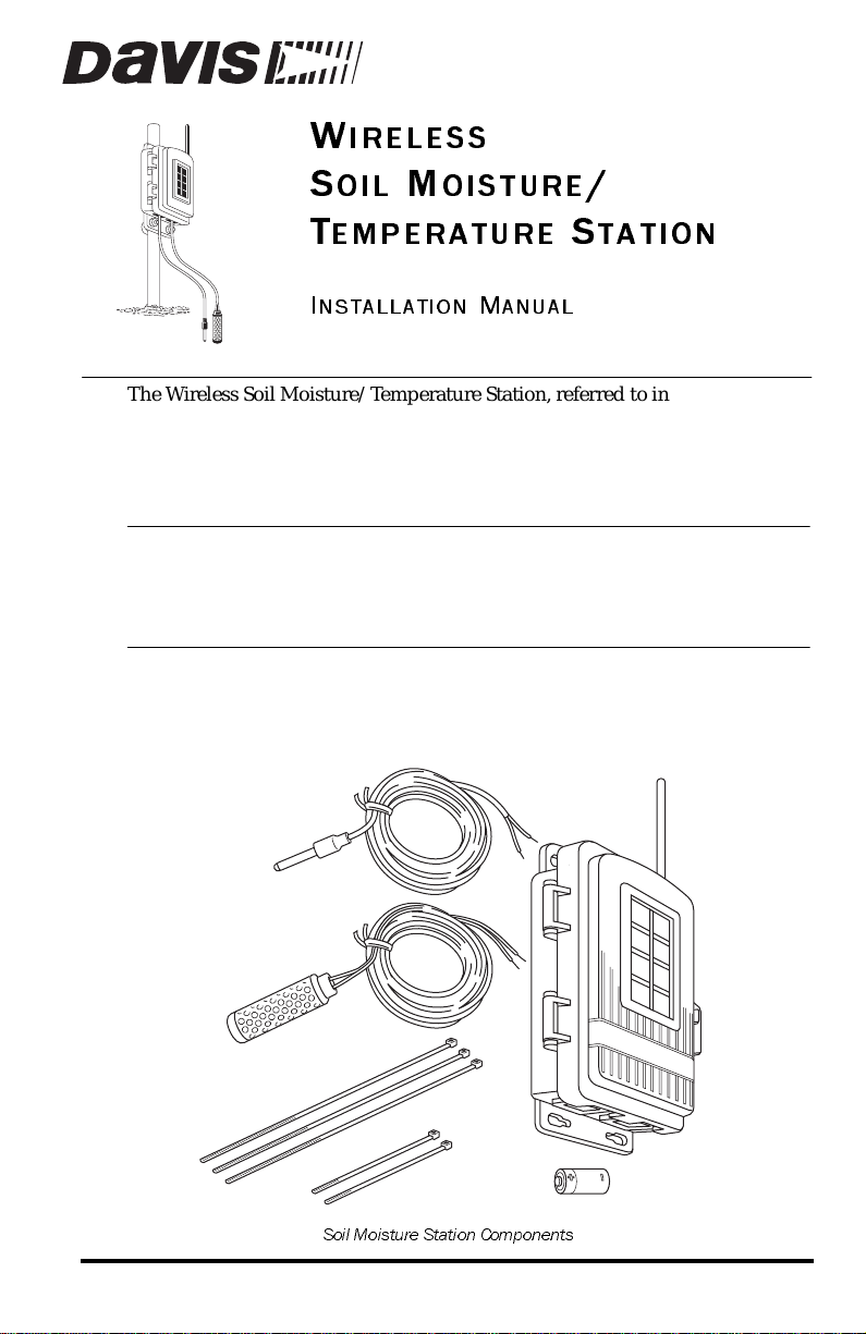
The Wireless Soil Moisture/Temperature Stat ion, referred to in this document
as the Soil Moisture Station, is for use with Wireless Vantage Pro
tions. One Soil Moisture Station can be installed per Vantage Pro Weather Station. Up to four WATERMARK soil moisture sensors and four multitemperature probes can be installed in a Soil Moisture Station .
Note: The Soil Moisture Station requires Vantage Pro console firmware dated Oct 25
2001 or later. (Press and hold the DONE key then press the UP arrow (+) key to
displ ay the console firmware level.) Con tact Dav is Technical Support if your
console requires an upgrade. Contac t informa tion is located in the back of this
manual.
®
Components
The Soil Moisture Station includes the following components and mounting
hardware:
Shelter
Temperature Probe
with 15' (4.6 m) of cable
Weather Sta-
Soil Moisture Sensor
with 15' (4.6 m) of cable
Soil Moisture Station Components
8" Cable Ties
4" Cable Ties
3-Volt Lithium Battery
Product # 6361

U-Bolts
1/4" Flat Washers
1/4" Lock Washers
1/4" Hex Nuts
Mounting Hardware
1/4" x 1-1/2"
Lag Screws
Tools for Setup
In addition to the components shown, you will need some or all of the following materials:
• Adjustable wrench or 7/16" wrench
• Ballpoint pen or paper clip (small pointed object of some kind)
• Drill and 3/16" (5 mm) drill bit (if mounting on a vertical surface)
• Stepped Sensor Installation Tool (see page 13)
Installation Steps
For ease of installation and use of your Soil Moisture Station, please follow
steps in the order presented.
• Preparing the Soil Moisture Station, page 2
• Choosing a location to mount the station, page 6
• Mounting the Soil Moisture Station, page 8
• Installing soil moisture sensors, page 10
• Using soil moisture readings, page 15
• Troubleshooting soil moisture sensors, page15
Preparing the Soil M oisture Station
The following illustration shows the location of the DavisTalk transmitter DIP
Switches, the battery mounting location, and the terminal blocks used to
connect the soil moisture sensors and temperature probes.
Inserting the Battery and Connecting the Sensors
1. Insert the 3-volt lithium battery into the battery holder , matching the “+”
sign on the battery with the “+” sign next to the battery mounting brackets.
• Note the location of the DIP switches. You will work with them during
the next installation step.
Page 2 Wireless Soil Moisture/ Temperature Station
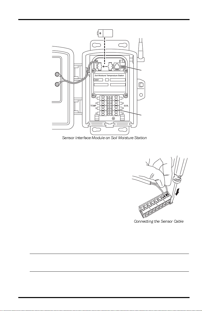
3-Volt
Lithium Battery
DIP
Switches
Terminal
Blocks
Sensor Interface Module on Soil Moisture Station
2. Temporarily connect a temperature probe to
the TEMP 1 terminal bl ock connector.
• Use a pen or small screwdriver to open
the connector “jaws” as shown in the
illustration.
• While the jaws are open, insert the temperature probe leads, then let the connector jaws close in on the lead.
3. Temporarily connect a soil moisture probe to
the SOIL 1 terminal block connector.
• Use a pen or small screwdriver to open
Connecting the Sensor Cable
the connector “jaws” as shown in the
illustration.
• While the jaws are open, insert the temperature probe leads, then let the
connector jaws close in on the lead.
Note: At least one tem perature probe or soil moisture sensor need to be temporarily
installed in order to test communications between the Soil Moisture Station and
the console.
Prepar ing the S oil Moisture Station Page 3
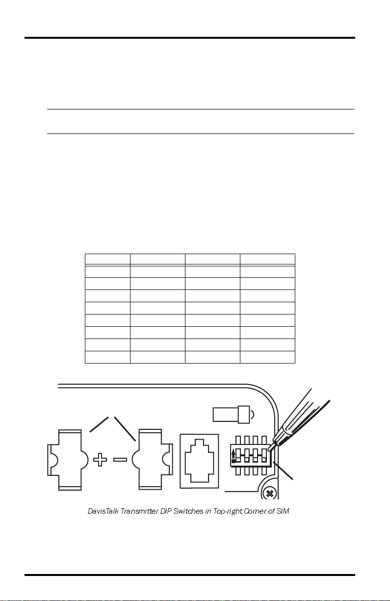
Setting the DavisTalk Transmitter ID
Each wireless transmitting station must be set to one of eight DavisTalk transmitter IDs. DIP sw i tches #1, 2 and 3 on the SIM allow you to control the ID —
the “channel” the station will transmit on. (DIP switch #4 is used for transmission testing, not for transmitter ID.)
Note: A Davi sTal k t ran sm it ter and r eceiv er c omm un icat e wi t h e ac h oth er o nl y wh en bo th
are set to the same ID.
The factory default transmitter ID is ‘1’. Looking at the table below , you can see
that means the DIP switches are in the OFF position when each transmitting
station leaves the factory. This is true for all of Davis’ wirel ess equipment .
1. Verify the Davi sTalk channel used by your ISS, as well as all o ther Davi sTalk
channels al ready in use by your Vantage Pro Weather Statio n.
2. Configure the Soil Moisture Station to a DavisTa lk channel not already in
use.
3. Use a ballpoint pen or paper clip t o toggle DIP switches #1, 2, and 3. The settings for transmitter IDs 1 – 8 are shown in the table below:
ID CODE SWITCH 1SWITCH 2SWITCH 3
#1 (default) OFF OFF OFF
#2 OFF OFF ON
#3 OFF ON OFF
#4 OFF ON ON
#5 ON OFF OFF
#6 ON OFF ON
#7 ON ON OFF
#8 ON ON ON
.
Battery Holder
ON
1234
DIP Switches
DavisTalk Transmitter DIP Switches in Top-right Corner of SIM
Page 4 Wireless Soil Moisture/ Temperature Station

Setting Console/Receiver(s) to Same ID
1. Put your console into Setu p Mode — press and hold th e DONE k ey and
press the DOWN (-) arrow key.
The console will show you Screen 1: Transmitters. Y ou should see the word s:
“RECEIVING FROM...” and “STATION NO.” followed by the transmitter
IDs that your console det ects. One of these should be the I D number you just
set on the Soil Moisture Station transmitter. If you don’t see it, make sure the
console is within 10' of the transmitter, and verify that you set the DIP
switches correctly. If you still don’t see it, go to “TEST mode” on the next
page.
2. Press the DONE key to move on to Screen 2: Sele cting Transmitters.
Setup Mode – Screen 2 is where you will set the console to recognize signals
on that ID as coming from a Soil Moisture Station.
3. Press the LEFT (<) or RIGHT (>) arrow key, or the STATION key, to scroll
through transmitter IDs.
When you see the ID you chose for the Soil Moisture Station, use the UP (+)
or DOWN (-) arrow keys to activate reception of that ID code. Make sure the
screen shows “ON”.
4. Press the GRAPH key until the word “SOIL” appears.
5. To exit Setup Mode, press and hold the DONE key.
Note: See the Vantage Pro User’s Manual & Setup Guide: “Setup Mode – Screen 2:
Selecting Transmitters” for more information.
Testing Soil Moisture Station Communications
1. Press the TEMP key until you see “SOIL MOIST” displayed on the console
screen where the inside temperatur e is usu ally disp layed.
• If you see SOIL MOIST and no number, you are seeing the moisture and
temperature readings for sensor pair #1.
2. If you continue to press the TEMP key, you will see the readings for sensor
pairs #2, #3, and #4.
• If no sensors are installed the reading will be dashed out.
3. A soil moistur e or temperature reading confirms co mmunication between
your Soil Moisture Station and the console.
• Disconnect the soil moisture sensor and temperature probe that were
temporarily installed to test communications.
• Go on to “Choosing a Location to Mount the Station” on page 6.
If your console does not show a soil moisture or soil temperature reading, proceed to “Troubleshooting Communication Problems
Prepar ing the Soil Mois ture Station Page 5
 Loading...