

Davis 6332 Installation Manual
ANEMOMETER TRANSMITTER KIT
#
INSTALLATION MANUAL
This manual describes how to install the Anemometer Transmitter Kit for a Wireless Vantage Pro2
TM
Weather Station. The kit enables you to connect the anemometer from your Integrated Sensor Suite (ISS) to its own transmitter, so it can be
located away from the ISS and communicate directly with your console/receiver.
Components
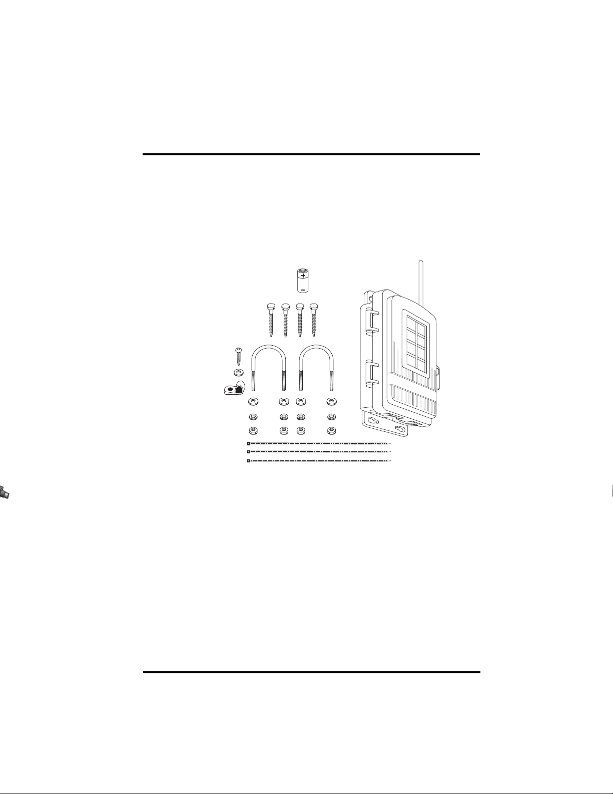
The Anemometer Transmitter Kit includes the following components and mounting
hardware:
Transmitter Shelter
1/4" x 1-1/2" Lag Screws
6 x 1/2" (3.5 x 12 mm)
Self-Threading Screw
#6 Washer
Cable Clamp
1/4" Flat Washers
1/4" Lock Washers
1/4" Hex Nuts
8" Cable Ties
3-Volt
Lithium
Battery
U-Bolts
Tools for Setup
In addition to the kit, you will need some or all of the following materials:
• Adjustable wrench or 7/16" wrench
• Compass or local area map
• Ballpoint pen or paper clip (small pointed object of some kind)
• Drill and 3/16" (5 mm) drill bit (if mounting on a vertical surface)
• Carpenter’s level (if mounting on a vertical surface)
If You Are Installing the ISS and the Anemometer Transmitter Kit
at the Same Time
Install your ISS first, following the instructions in the ISS manual. However, during
the step “Preparing the ISS for Installation,” DO NOT connect the anemometer
cable to the SIM. When you have mounted the rain collector side of the ISS and are
ready to mount the anemometer, follow the instructions in this manual starting with
“Preparing the Anemometer Transmitter” on page 3.
1

Installation Steps
The following is an outline of the steps necessary to install the Anemometer Transmitter Kit. These steps are used as section headings in this manual and are explained
in greater detail in the appropriate section.
• Remove the anemometer from its current location (if necessary)
• Disconnect the anemometer from the ISS transmitter
• Unfasten and remove the anemometer
• Prepare the anemometer transmitter
• Insert the battery
• Plug the anemometer cable into the transmitter
• Set the transmitter ID on the anemometer transmitter using DIP switches
• Set the console to recognize the signals
• View current wind data
• Putting your anemometer transmitter into TEST mode
• Choose a location for the anemometer transmitter
• Test transmission from the proposed mounting location
• Mount the anemometer and transmitter shelter in the new location
• A note on securing cables
• Troubleshooting
• Contacting Davis Technical Support
Removing the Anemometer from its Current Location
The following two steps assume that your ISS is already mounted. If it is in a high
location such as a rooftop, please read through the instructions before climbing up,
and watch your balance while installing your Anemometer Transmitter Kit.
Disconnecting Anemometer from ISS Transmitter
Open the SIM Box and unplug the anemometer cable from the receptacle labeled
WIND on the SIM. Guide the anemometer cable through and free from the grommet. Or in the case of the Vantage Pro2 SIM Box, guide the anemometer cable free
of the cable access port by first removing the foam insert and then guiding the cable
out of the box. When finished, make sure to replace the foam insert ensuring that the
Access Port is filled and free of any voids.
If Your ISS is Mounted as a Single Unit (Both Sides Together on
a Pole)
Unfasten the anemometer:
1. Remove the black rain collector cone from its base by rotating cone counter-
clockwise until its latches line up with openings in the base and you can lift it off.
It is much easier to reach the hex nuts with a wrench if you remove the rain
collector cone first.
2. Using an adjustable wrench or 7/16" wrench, remove the hex nuts and washers
holding the anemometer’s plastic mounting base on the pole. Set the anemometer
down for a moment.
2
3. Remove the hex nuts and washers holding the rain collector side on the pole.
es
p
SENSOR
INTERFACE
MODULE
SUN
RAIN
WIND
TEMP
HUM
Retrieve the U-bolt that was holding the anemometer.
4. Using the washers and hex nuts, fasten the rain collector side back onto the pole.
Flat washer goes on first, then lock washer, then hex nut.
5. Put the rain collector cone back on. Rotate the cone clockwise until the latches
slide into place.
If Your Anemometer is Mounted by Itself
Unfasten it: use an adjustable wrench or 7/16" wrench to remove the hex nuts or lag
screws.
Preparing the Anemometer Transmitter
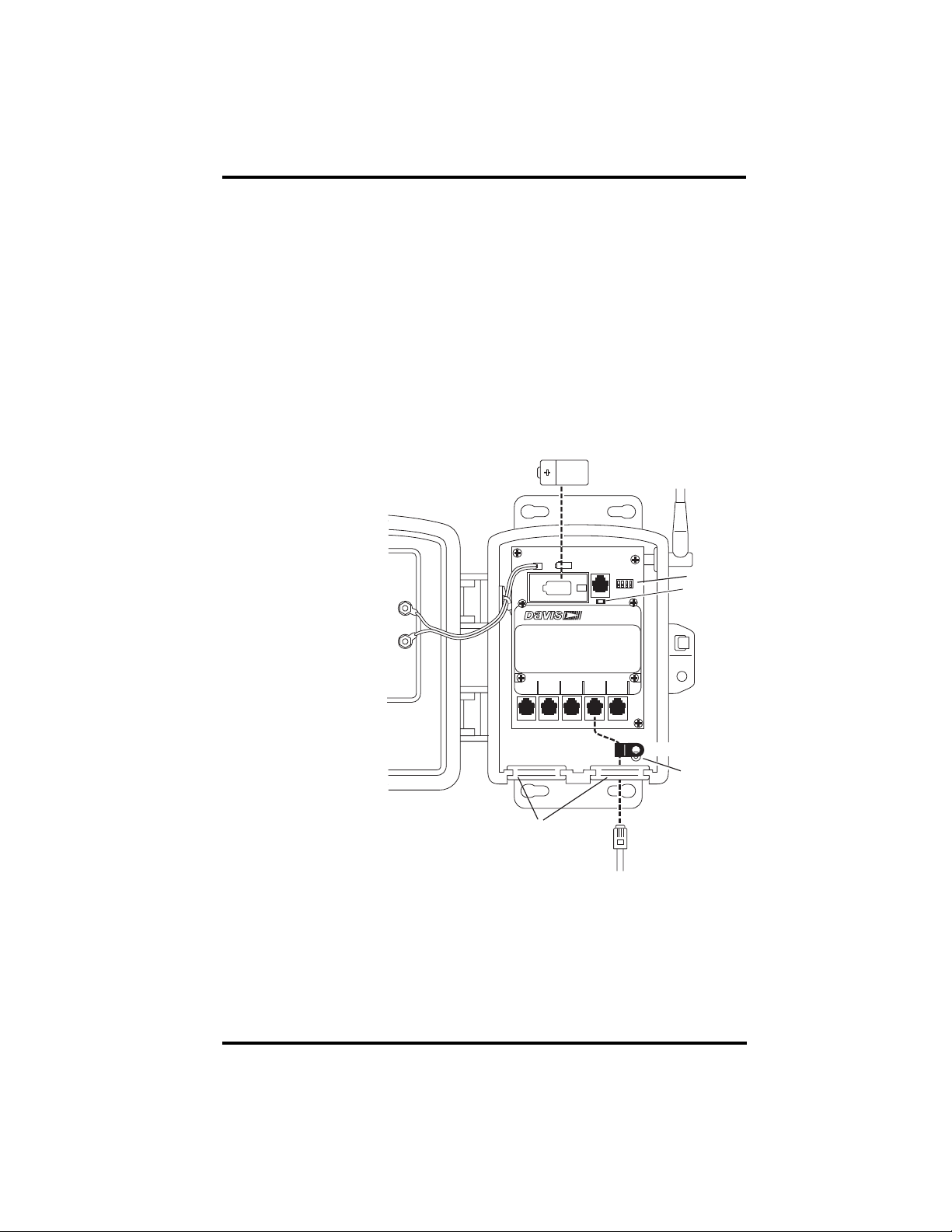
The illustration below shows the Sensor Interface Module, or “SIM”, inside the
transmitter shelter.
1. Insert the 3-volt
lithium battery into
the battery holder,
matching the “+”
sign on the battery
with the “+” sign on
the SIM.
2. Push the end of the
+
anemometer cable up
through the square
black grommet into
the transmitter shelter. Every Davis
UVUVSUN
shelter has two of
these grommets to
provide weatherresistant entrances
for cables. In this
case, use the grommet on the right. Y ou
can also remove the
Square Black Grommets
grommet, thread the
cable through it and
then replace the grommet in the shelter if that is easier for you.
3. Plug the end of the anemometer cable into the receptacle labeled WIND on the
SIM.
4. Place the cable clamp over the anemometer cable between the grommet and the
receptacle. Secure the cable clamp to the shelter by threading the provided #6
screw through the washer, then cable clamp and then screwing it into the cable
clamp mount inside the housing. (See the above illustration.)
-
RAIN
3-Volt
Lithium Battery
SENSOR
INTERFACE
MODULE
TEMP
WIND
HUM
Cable Clamp
Anemometer
Cable
DIP Switch
Test LED
Cable Clam
Mount
3
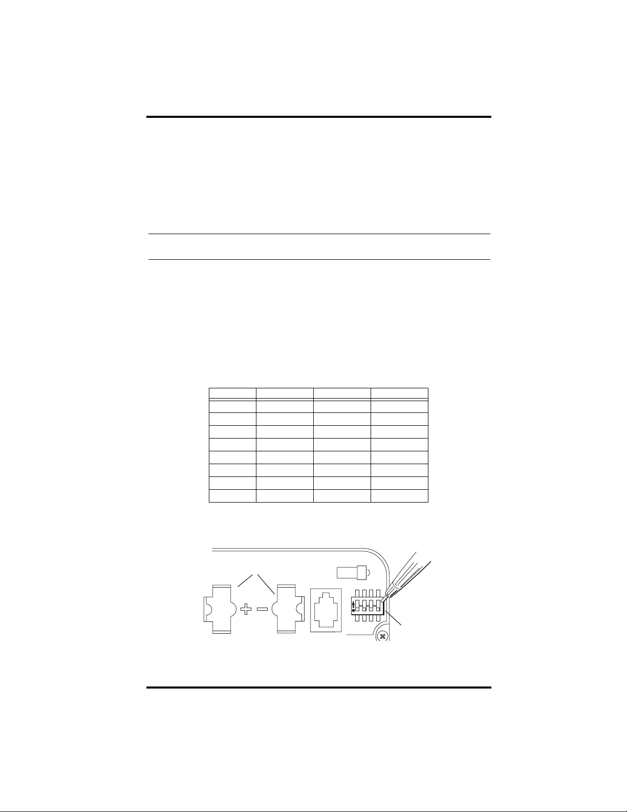
5. Locate the DIP switches. You will work with them during the next installatio n
s
step.
Setting the Transmitter ID
Each wireless transmitting station must be set to one of eight transmitter IDs. DIP
switches #1, 2 and 3 on the SIM allow you to control the ID — the “channel” the
station will transmit on. (DIP switch #4 is used for transmission testing, not for
transmitter ID.)
Tip: The transmitter and your console communicate with each other only when both are set to the same
ID.
The factory default transmitter ID is ‘1’. Looking at the table below, you can see
that means all three DIP switches are in the OFF position when each transmitting
station leaves the factory, whether it is an ISS, an anemometer transmitter, or
another kind of station.
The ISS is included with every Wireless Vantage Pro, and the console/receiver is
factory set to find the ISS on ‘1’. Since it is likely that your ISS is already set to
ID ‘1’, you will need to set the ID of your anemometer transmitter to a different ID number. Use a ballpoint pen or paper clip to toggle DIP switches #1, 2,
and 3. The settings for transmitter IDs 1 – 8 are shown in the table below:
ODE SWITCH 1SWITCH 2SWITCH 3
ID C
#1 (default) off off off
#2 off off ON
#3 off ON off
#4 off ON ON
#5 ON off off
#6 ON off ON
#7 ON ON off
#8 ON ON ON
Use this table to ensure that each wireless transmitting station in your system is
broadcasting on its own transmitter ID.
Battery Holder
ON
1234
DIP Switche
DIP SWITCHES IN TOP-RIGHT CORNER OF SIM (ILLUSTRATION HAS BEEN ENLARGED FOR CLARITY)
4
 Loading...