

Integrated
Sensor Suite
For Vantage Pro2 , Vantage Pro2 GroWeather
and Vantage Pro2 Plus
Davis Instruments, 3465 Diablo Avenue, Hayward, CA 94545-2778 U.S.A. • 510-732-9229 • www.davisnet.com
™
™
R

Contents
Introduction ...........................................................................................1
Included Components and Hardware ....................................................2
Prepare the ISS for Installation..............................................................5
Cabled ISS Assembly ..........................................................................12
Wireless ISS Assembly........................................................................15
Plan the ISS Installation ......................................................................20
Install the ISS.......................................................................................24
Maintenance and Troubleshooting.......................................................34
Contacting Technical Support..............................................................43
Appendix: Specifications.....................................................................44
FCC Part 15 Class B Registration Warning
This equipment has been tested and found to comply with the limits for a Class B digital device, pursuant to
Part 15 of the FCC Rules. These limits are designed to provide reasonable protection against harmful
interference in a residential installation. This equipment generates, uses, and can radiate radio frequency
energy and, if not installed and used in accordance with the instructions, may cause harmful interference to
radio communications.
However, there is no guarantee that interference will not occur in a particular installation. If this equipment
does cause harmful interference to radio or television reception, which can be determined by turning the
equipment on and off, the user is encouraged to try to correct the interference by one or more of the following
measures:
• Reorient or relocate the receiving antenna.
• Increase the separation between the equipment and receiver.
• Connect the equipment into an outlet on a circuit different from that to which the receiver is connected.
• Consult the dealer or an experienced radio/TV technician for help.
Changes or modification not expressly approved in writing by Davis Instruments may void the warranty and
void the user's authority to operate this equipment.
FCC ID: IR2DWW6328
IC: 378810-6328
EC EMC Compliance
This product (models 6152, 6153, 6163, 6322, 6323, 6327, 6328, 6334, 6820, 6825 OV EU UK) complies
with the essential protection requirements of the Radio Equipment Directive 2014/53/EU. RoHS compliant.
The complete Declaration of Conformity is on our website at https://www.davisnet.com/legal. RoHS
Compliant.

Introduction
The Integrated Sensor Suite (ISS) collects outside weather data and sends the data to
a Vantage Pro2 console. The wireless ISS can also transmit data to wireless Vantage
Connect, Vantage Vue console, Envoy8X, or wireless Weather Envoy. The wireless
ISS is solar-powered and sends data via radio. The cabled ISS sends data via cable to
one cabled Vantage Pro2 console, cabled Weather Envoy, or cabled Vantage Connect
and receives power via the console, Envoy or Vantage Connect cable.
Tip: One wireless ISS can transmit to any number of receivers within its range, so you
can add additional consoles to use in different rooms.
All Vantage Pro2 ISSes include a rain collector, temperature sensor, humidity sensor
and anemometer. Temperature and humidity sensors are mounted in a passive or fanaspirated radiation shield to minimize the impact of solar radiation on sensor
readings. The anemometer measures wind speed and direction and can be installed
adjacent to the ISS or apart from it. See “Locating the ISS and Anemometer” on
page 20 for siting guidelines.
The transmitter shelter contains the “brain” of the ISS: the sensor interface and the
transmitter. It collects outside weather data from the ISS sensors and then transmits
the data to your Vantage Pro2 console, Vantage Vue console (wireless only),
Weather Envoy, Envoy8X (wireless only), or Vantage Connect.
Other versions of the ISS have additional features:
• Wireless Vantage Pro2 with Fan (product number 6153): Includes a 24-Hour
Fan-Aspirated Radiation Shield.
• Wireless and cabled Vantage Pro2 Plus (product numbers 6162 & 6162C):+
Includes a pre-installed solar radiation sensor and an ultra-violet (UV) radiation
sensor.
• Wireless Vantage Pro2 Plus with Fan (product number 6163): Includes UV
and solar sensors, and a 24-Hour Fan-Aspirated Radiation Shield.
• Wireless Vantage Pro2 with Solar and Daytime Fan (product number 6334):
Includes a solar sensor (for ET readings) and a Daytime Fan-Aspirated Radiation
Shield.
• Wireless and cabled GroWeather (product numbers 6820 & 6820C) include a
Daytime Fan-Aspirated Radiation Shield to minimize the impact of soalr
radiation on sensor readings and a solar radiaton sensor.
• Wirelss and Cabled GroWeather with 24-Hour Fan-Aspirated Raiation
Shield (product number 6825 & 6825C) and solar radiation sensor
Tip: Separate Solar Sensor (prod. no. 6450), UV Sensor (prod. no. 6490), Sensor
Mounting Shelf (prod. no. 6673), and Daytime Fan-Aspirated Radiation Shield (prod.
no. 7747) are available to upgrade a standard ISS.
1
Included Components and Hardware
The ISS comes with all the components and hardware shown in the following
illustrations. If you purchased your ISS as part of a weather station package
containing the Vantage Pro2 console, additional components may be included in the
package that are not shown here.
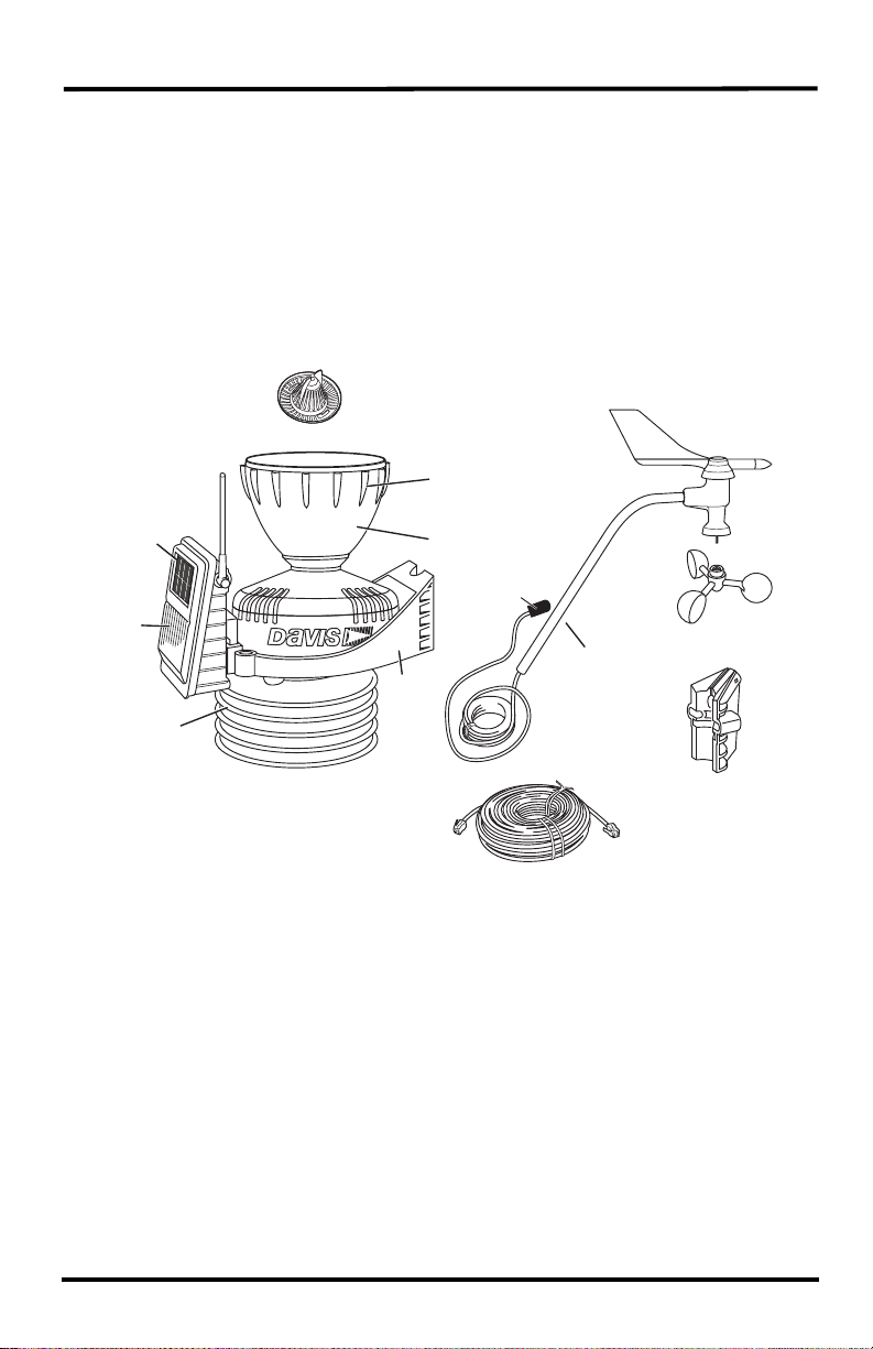
Components
VANTAGE PRO2 ISS
Debris Screen
(place inside cone
after installation)
Solar Panel
(wireless
ISS only)
Transmitter
Shelter
Standard
Passive
Radiation
Shield
with standard radiation shield
Bird Spike
Socket
Rain Collector
Protective
Cap
Anemometer
Rain
Collector
Base
Console Cable 100' (30 m)
(Cabled ISS Only)
Anemometer Cable
40' (12.2 m)
Arm
Anemometer
Vane
Anemometer
Base
Control
Head
Wind Cups
2
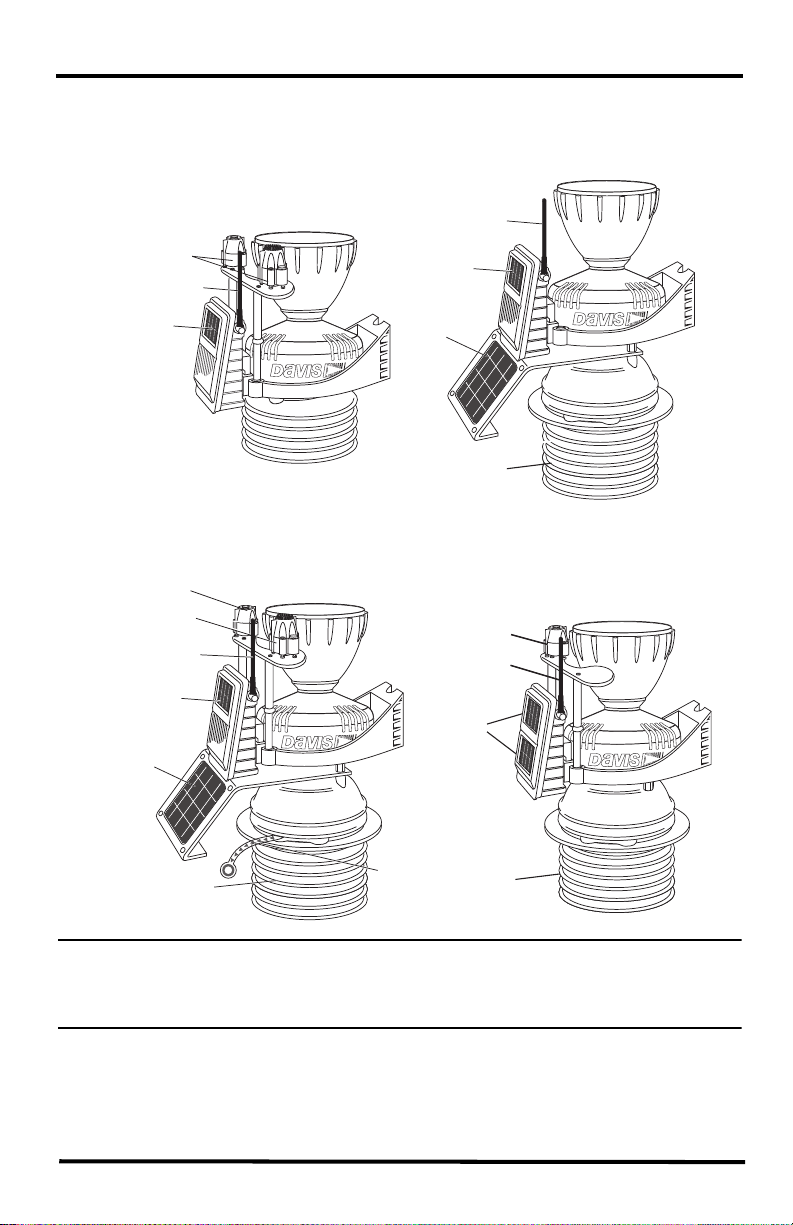
Other versions of the ISS have additional features and parts:
VANTAGE PRO2
VANTAGE PRO2 PLUS
with Standard Radiation Shield
UV and
Solar Radiation
Sensors
Antenna
(wireless only)
Transmitter
Solar Panel
(wireless only)
with 24-Hour Fan-Aspirated Shield
Antenna
(wireless only)
Transmitter
Solar Panel
(wireless only)
Fan
Solar Panel
24-Hour
Fan-Aspirated
Radiation Shield
VANTAGE PRO2 PLUS and GroWeather
with 24-Hour Fan-Aspirated Shield
Solar Radiation
Sensor
UV Sensor
(Vantage Pro2 Plus
only)
Antenna
(wireless only)
Transmitter
Solar Panel
(wireless only)
Fan
Solar Panel
24-Hour
Fan-Aspirated
Radiation Shield
Battery
Pull Tab
and Daytime Fan-Aspirated Shield
Solar Radiation
Sensor
Antenna
(wireless only)
Solar Panels
Daytime
Fan-Aspirated
Radiation Shield
GroWeather
with Solar Radiation Sensor
Note: If the ISS has UV and solar radiation sensors, do not touch the small white diffusers on
top of the sensors. Oil from skin reduces their sensitivity. If you are concerned that you
have touched the diffusers at any time during the installation, clean the UV diffuser with
a soft cloth.
3
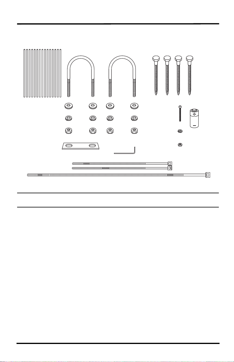
Hardware (Included)
Bird Spikes (15)
1/4" Flat Washers
1/4" Lock Washers
1/4" Hex Nuts
Backing Plate
Cable Ties
U-Bolts
.05" Allen
Wrench
1/4" x 3" Lag Screws
#4 x 1-1/8"
Machine Screw
#4 Tooth
Lock Washer
#4-40 Hex Nut
3-Volt
Lithium
Battery
(wireless
models
only)
Some of the hardware is optional based on how the ISS is assembled and installed.
Note: If any of the hardware components are missing or not included, contact Customer
Service toll free at 1-800-678-3669 about receiving replacements.
Tools for Setup
• Small Phillips head screwdriver (electric if possible)
• Adjustable wrench or 7/16" wrench
• Compass or local area map
• Ballpoint pen or paper clip (or other small pointed object)
• Drill and 3/16" (5 mm) drill bit (if using lag bolts)
• Small hammer (if installing optional bird spikes)
4
Prepare the ISS for Installation
Follow the steps in the order they are presented as each builds on tasks completed in
previous steps. These steps apply to all versions of the ISS, unless otherwise noted.
Tip: Use a well-lit work table or work area to prepare the ISS for installation.
Assemble the Anemometer
The anemometer measures wind direction and speed. The anemometer arm comes
partially assembled with the wind vane attached.
Note: Do not remove the vane.
Please locate the following parts to prepare the anemometer:
• Anemometer arm (wind vane and cable already attached)
• Anemometer base
• Wind cups
• Allen wrench (0.05")
• #4 machine screw, #4 tooth-lock washer, #4 hex nut
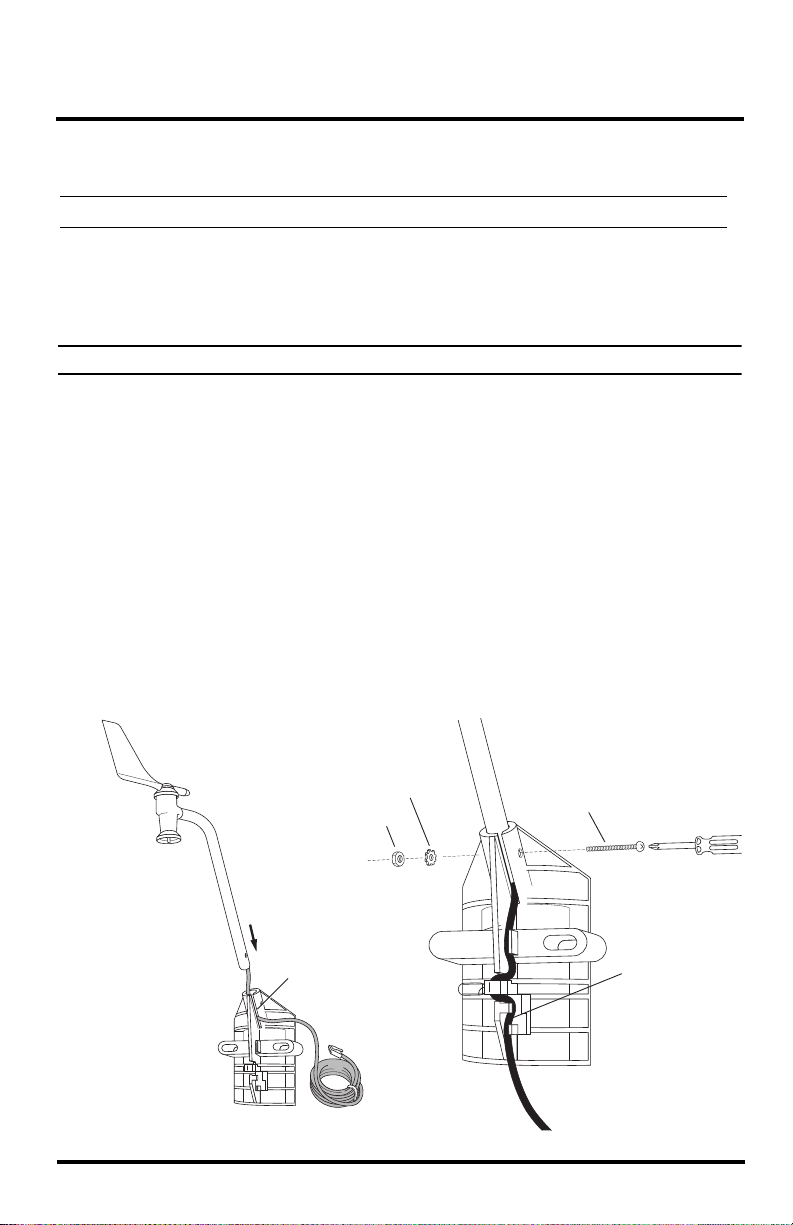
Attach the Anemometer Arm to Base
1. Insert the anemometer arm into the base, sliding the cable through the notch in the
base as shown in illustration.
2. Be sure to line up the small hole in the arm with the holes in the base.
3. Insert the machine screw through the holes in the base and arm. It may be helpful
to use a screwdriver to insert the screw.
Insert
anemometer arm
into base
Slide cable
through notch
Hex Nut
#4 Tooth
Lock Washer
#4 x 1-1/8”
Machine Screw
IMPORTANT:
Make sure cable
is secure in channel
5
4. Slide the tooth-lock washer and hex nut onto the machine screw. Tighten the hex
nut while holding the screw with a Phillips head screwdriver to prevent it from
turning.
5. Press the sensor cable firmly and completely into the zig-zagging channel in the
base, starting from the arm and progressing downward to the bottom of the base.
This provides strain relief for the cable.
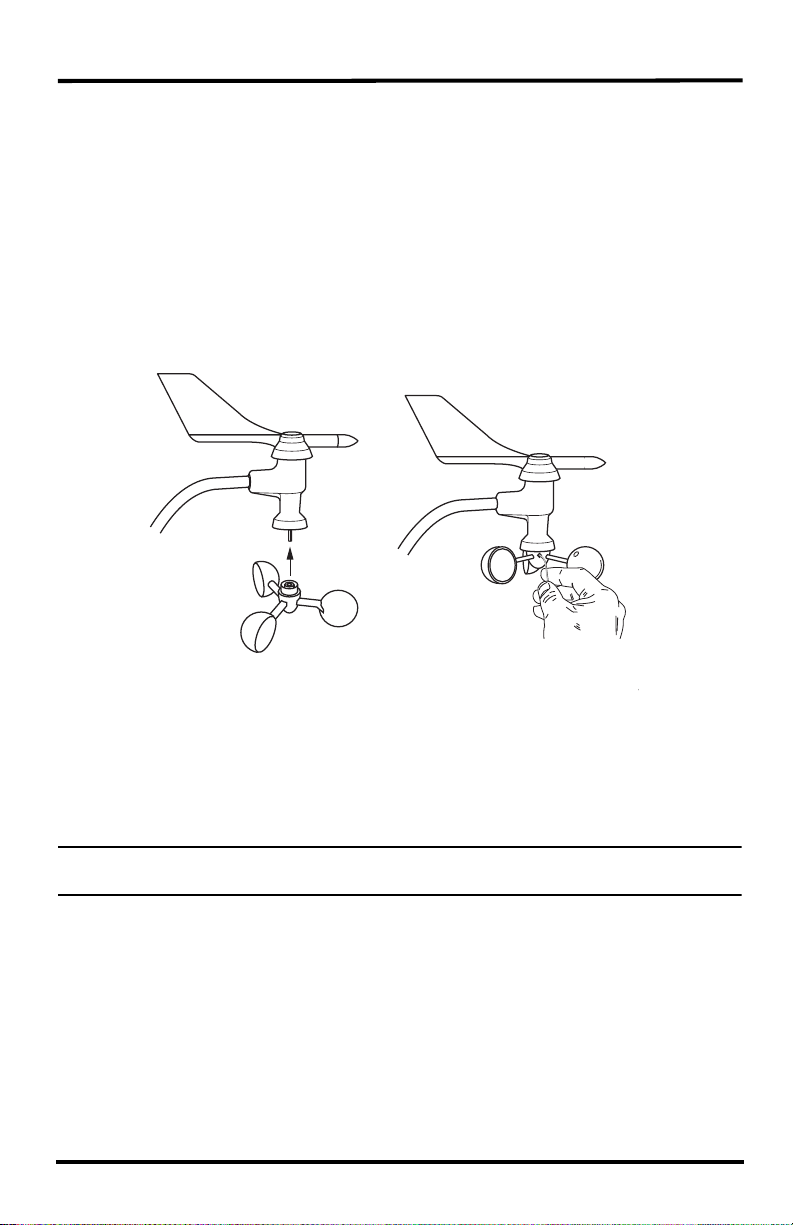
Attach the Wind Cups
1. Push the wind cups up onto the anemometer’s stainless steel shaft, sliding them
up the shaft as far as possible.
Push cups
onto stainless
steel shaft
Attaching the Wind Cups
Tighten
set screw
with Allen
wrench
2. Use the Allen wrench provided to firmly tighten the set screw on the side of the
wind cups.
The wind cups should drop slightly when you let go.
3. Spin the wind cups. If they spin freely, the anemometer is ready and can be set
aside while you prepare the rest of the ISS for installation.
Note: If the wind cups don’t spin freely, take them off and repeat the wind cup installation
process.
6
Check Sensor Interface Connections and Connect the
Anemometer Cable
The sensor interface is located in the transmitter shelter on the front of the ISS
station. It contains all the connections for the weather sensors of the ISS. Follow the
steps below to check the sensor interface and ensure that all sensors are connected
properly.
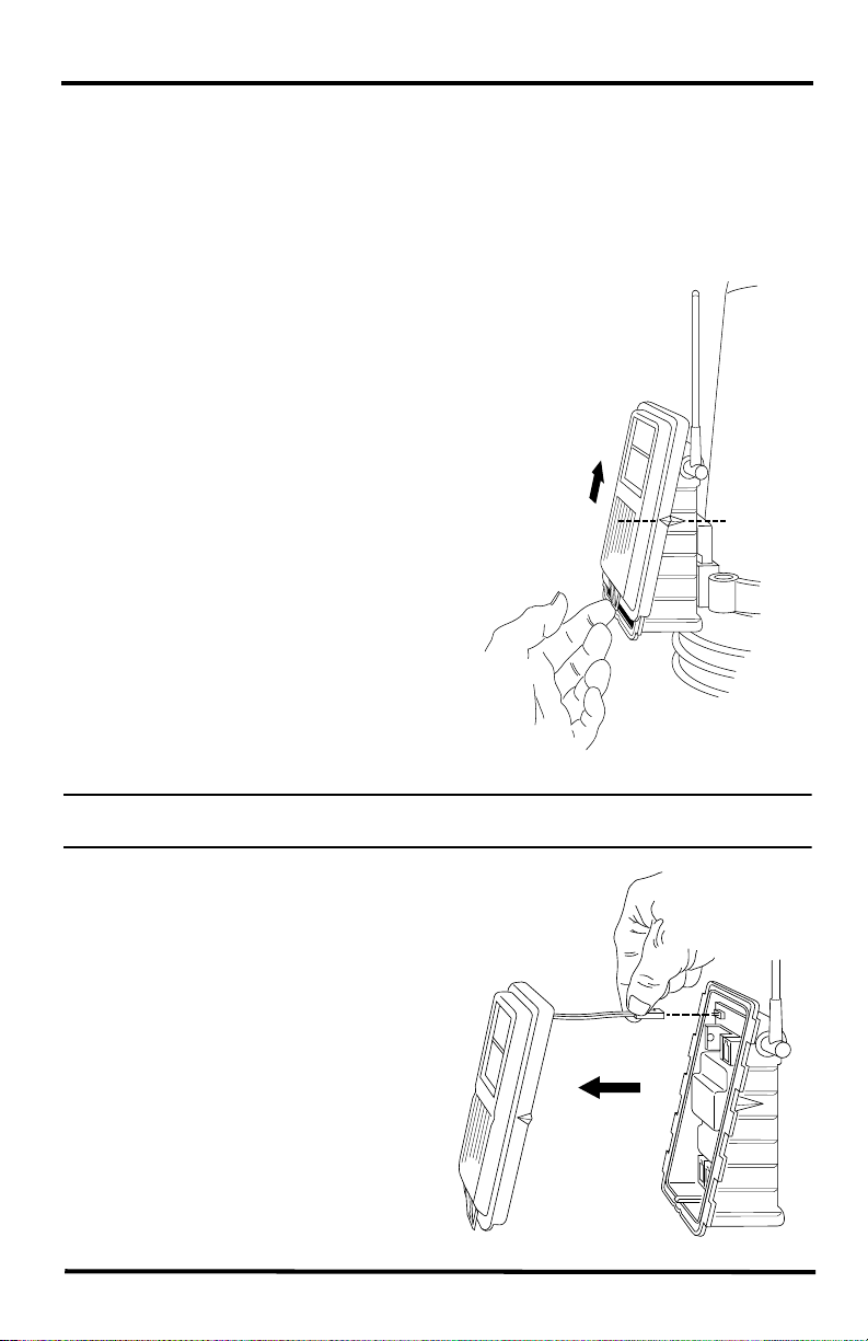
Open the Transmitter Shelter
1. Locate the white box with the solar
panel containing the sensor interface
on the front of the ISS unit. The cabled
model does not have a solar panel.
2. Locate the white tab at the bottom
center of the shelter cover.
3. Pull the tab away from the box while
sliding the cover up.
4. Look on the side of the shelter. The box
cover can be easily removed from the
box when the alignment indicator on
the cover is lined up with the alignment
indicator on the box
5. Pull the cover off the box, being
careful not to stress the solar panel
cable when removing the cover.
6. The sensor interface is visible once the
cover has been removed.
Note: See “Sensor Interface” on page 46 for information on locating the components and
points of interest on the sensor interface.
Optional: Disconnect the solar panel
connection wire (wireless versions)
and the fan cable (fan versions)
The solar panel on the box cover is
connected to the sensor interface by a
wire. If your ISS has a fan, the fan
cable will also connect the cover to the
sensor interface. If the cover cannot be
set aside while still connected to the
sensor interface safely, those cables
can be disconnected.
7
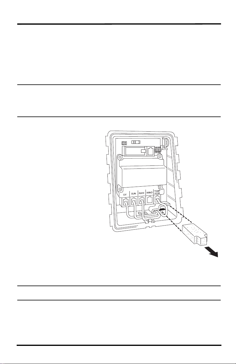
Check the Factory Installed Sensor Connections
1. Verify that the rain collector and temperature/humidity sensor cables are plugged
into the receptacles labeled RAIN and TEMP/HUM on the sensor interface.
2. If your ISS includes UV and/or solar radiation sensors, verify that the sensor
cables are plugged into the receptacles labeled UV and SUN on the sensor
interface.
Connect the Anemometer Cable to the Sensor Interface
Note: The anemometer comes with 40 feet (12 meters) of cable to allow for mounting the
anemometer separately from the rain collector and other sensors. The cable is coiled
and secured at the factory with enough cable unwound from the coil to allow you to
work with it and to allow the anemometer to be mounted on the same pole as the rain
collector.
1. Remove the protective cap from the RJ jack on the anemometer cable.
2. Pull the foam insert out of
cable access port and set
the foam insert aside.
3. Insert the anemometer
cable end into the cable
access port from beneath
Sensor
Interface
the box.
4. Slide the cable through
the cable access port with
the connector lever down.
5. Firmly insert the end of
the anemometer cable
into the connector labeled
WIND. The lever clicks
Foam
Insert
into place.
6. Firmly insert the foam in
between the cables and at
the top of the cable access
Note: Only Plus models have UV and
solar cables already attached.
port, taking care to ensure
that the foam seals the
access port entirely, leaving no holes or gaps large enough for weather or insects.
You may have to stack the cables to allow the foam to fit.
Note: If you are assembling a cabled station, wait to reinsert the foam until cable assembly is
complete. See “Cabled ISS Assembly” on page 12.
8
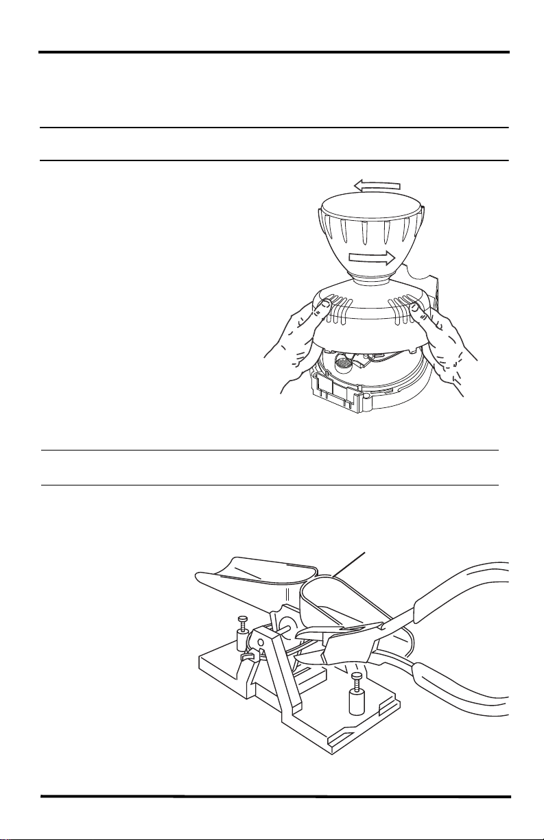
Prepare the Rain Collector
The tipping mechanism is secured at the factory to protect it from damage during
shipping.
Note: Be careful not to scratch the silver-colored coating on the tipping spoons under the
cone.
1. Remove the rain collector cone
from the ISS base by rotating
the cone counter-clockwise.
When the cone’s latches line
up with openings in the base,
lift the cone off the ISS base.
Twist off the rain collector cone
Tip: When new, the cone fits tightly in the base and may require extra pressure to
remove. Steady the ISS base between your knees when removing the cone.
2. Carefully cut and remove the plastic tie that holds the tipping spoons in place
during shipping (usually yellow or white in color).
3. If desired, insert
Tipping Spoons
the Metric
Measurement
Adapter.See
“Optional: Insert
the Metric
Measurement
Adapter” on
page 10.
4. Temporarily
reinstall he rain
collector cone
until you are ready
to mount the ISS
outside.
Cut the plastic tie
9

Optional: Insert the Metric Measurement Adapter
The rain collector tipping spoon mechanism takes measurements in 0.01'' (US
versions) or 0.2 mm (M, EU, UK and OV) increments for each tip of the spoons. If
you have a US version and would like to convert it to a metric measurement, you can
insert the metric adapter that is included in your hardware kit.
Note: Inserting the metric measurement adapter converts the rain collector to take
measurements in 0.2 mm increments for each tip of the spoons. The console must be
configured to 0.2 mm as well. See the Vantage Pro2 Console User Manual for more
information.
To install the metric adapter:
1. Find the metric adapter included in the hardware.
2. Locate the magnet between silver-colored, V-shaped arms of the tipping spoons.
3. Open the arms slightly
with one hand while
pulling the magnet out
with the other.
10
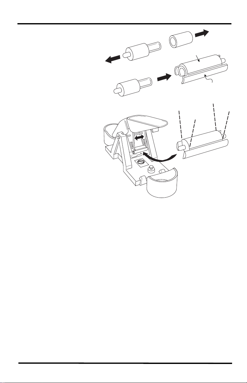
4. Separate an end cap from
one end of the magnet.
5. Slide the magnet, exposed
end of magnet first, into
the open slot of the metric
adapter.
6. Insert the metric adapter
and magnet between the
arms of the spoons, with
the top (solid side) of the
metric adapter facing up.
Top (closed)
Bottom (notched)
Next Steps
• See “Cabled ISS Assembly” on page 12 for assembling a cabled Vantage
Pro2 system
• See “Wireless ISS Assembly” on page 15 for assembling a wireless Vantage
Pro2 system.
11

Cabled ISS Assembly
Apply Power and Verify Communication with the
Console
The 100' (30 m) console cable provides power to the ISS and is used to send data
from the ISS to the console. The console cable can be extended up to 1000' (305 m)
in length with extension cables purchased from Davis Instruments.
With the console powered, plugging the console cable into the console powers the
ISS and establishes communication between the ISS and the console.
1. Locate the 100' console cable included with your system.
2. Pull the foam insert out of cable access port, if it has been reinserted. Insert the
console connector cable end into the cable access port from beneath the sensor
interface box. Slide the cable through the cable access port with the connector tab
down.
3. On the sensor interface, firmly insert either end of the 4-conductor cable into the
modular receptacle labeled COMM.
Comm
Sensor
Interface
4. If you haven’t powered up the console yet, refer to the installation instructions in
the Vantage Pro2 Console User Manual and apply power to the console.
5. On the bottom of your console, insert the other end of the console cable into the
modular receptacle labeled “ISS.”
6. Firmly insert the foam in between the cables and at the top of the cable access
port, taking care to ensure that the foam seals the access port entirely, leaving no
holes or gaps for weather or insects. See the graphic on page 8 for more
information on inserting the foam insert.
7. If the console is in Setup Mode, press and hold DONE until the Current Weather
screen displays. A flashing "X" in the lower left hand corner indicates that the
console is receiving data. Sensor readings from the ISS should display on the
screen.
From Cabled
Vantage Pro2
Console
12

Verify Data from the ISS Sensors
1. Near the center of the screen, look for the outside temperature (TEMP OUT).
2. Spin the wind cups to check wind speed, pressing WIND if necessary to alternate
between speed and direction in the compass rose.
3. Turn the wind vane and allow five seconds for the wind direction display to
stabilize before moving it again.
4. Approximately one minute after power-up the outside relative humidity (HUM
OUT) reading should be displayed on the console.
5. Check to see if your console is receiving rain readings. On your console screen,
look for the DAILY RAIN display. Remove the rain collector cone and tip the
spoon, then wait to see if the display registers a rain reading. Each tip indicates
0.01" or 0.2 mm of rain and may take up to a minute to register at the console. If
the spoons are tipped too quickly, the number on the console display may not
change.
6. If the ISS contains a UV sensor and/or solar sensor, press 2ND and then press
RAIN YR for current ultraviolet readings or press 2ND then press RAIN DAY for
solar radiation readings.
The UV reading displays in the center of the console. The solar reading displays
in the bottom right corner of the console display. UV and solar readings should be
zero or close to zero if the ISS is inside. Zero is a valid reading. Dashes(--) are
displayed if no data comes from the sensors.
7. Current weather data displayed on the console confirms communication.
Once the ISS has been powered and the console has successfully received accurate
readings from all the sensors, prepare the ISS for installation. Continue on to “Plan
the ISS Installation” on page 20 for more information.
If there is a communication problem between the wireless ISS and the console, see
below: “Troubleshooting Cabled ISS Communication” on page 14.
To make installation easier at a location, disconnect the console cable from the
sensor interface. Remove the foam and slide the cable out through access port. Once
a location for both the ISS and the console has been arranged, reinsert the cable
through the access port, into the console connector, and reinsert the foam.
13
 Loading...