

Page 1
®
Vantage Pro
Weather Envoy
Installation Manual
Product # 63 14 & 6314C
Page 2

FCC Part 15 Class B Registration Warning
This equipment has been tested and found to comply with the limits for a Class B digital
device, pursuant to Part 15 of the FCC Rules. These limits are designed to provide reasonable protection against harmful interference in a residential installation. This equipment generates, uses, and can radiate radio frequency energy and, if not installed and
used in accordance with the instructions, may cause harmful interference to radio communications.
However, there is no guarantee that interference will not occur in a particular installation.
If this equipment does cause harmful interference to radio or television reception, which
can be determined by turning the equipment on and off, the user is encouraged to try to
correct the interference by one or more of the following measures:
• Reorient or relocate the receiving antenna.
• Increase the separation between the equipment and receiver.
• Connect the equipment into an outlet on a circuit different from that to
which the receiver is connected.
• Consult the dealer or an experienced radio/TV technician for help.
Davis cables must be used for this equipment to comply with the relevant FCC regulations.Changes or modification not expressly approved in writing by Davis Instruments
may void the warranty and user’s authority to operate this equipment.
Product #: 6314 & 6314C
Part Number: 7395.181
Weather Envoy Installation Manual
Rev A Manual (September 26, 2002)
This product complies with the essential protection requirements of the EC EMC Directive 89/
336/EC..
(c) Davis Instruments Corp. 2002. All Rights Reserved.
3465 Diablo Avenue, Hayward, CA 94545-2778 U.S.A.
E-mail: info@davisnet.com • www.davisnet.com
510-732-9229 • Fax: 510-732-9188
Page 3

Table of Contents
Table of Contents
Welcome to the Weather Envoy! . . . . . . . . . . . . . . . . . . .1
Contents . . . . . . . . . . . . . . . . . . . . . . . . . . . . . . . . . . . . . . . . . . . . . . . .1
Required for Operation . . . . . . . . . . . . . . . . . . . . . . . . . . . . . . .1
All Weather Envoys: . . . . . . . . . . . . . . . . . . . . . . . . . . . . . . .1
Wireless Weather Envoy: . . . . . . . . . . . . . . . . . . . . . . . . . . .1
Cabled Weather Envoy: . . . . . . . . . . . . . . . . . . . . . . . . . . . .1
Optional Accessories . . . . . . . . . . . . . . . . . . . . . . . . . . . . . .2
Hardware Installation . . . . . . . . . . . . . . . . . . . . . . . . . . . .2
Hardware Requirements . . . . . . . . . . . . . . . . . . . . . . . . . . . . . . . . . . . .2
Local Connection Windows Computer Requirements . . . . . . . .2
Local Connection Macintosh Computer Requirements . . . . . . .2
Preparing the Envoy . . . . . . . . . . . . . . . . . . . . . . . . . . . . . . . . . . . . . . .3
Installing the Data Logger . . . . . . . . . . . . . . . . . . . . . . . . . . . . .3
Installing the Batteries . . . . . . . . . . . . . . . . . . . . . . . . . . . . . . . .4
Connecting AC Power . . . . . . . . . . . . . . . . . . . . . . . . . . . . . . . .5
Connecting a Cabled Envoy to the Integrated Sensor Suite (ISS) 5
Mounting the Envoy . . . . . . . . . . . . . . . . . . . . . . . . . . . . . . . . . .6
Local Computer Installation . . . . . . . . . . . . . . . . . . . . . . . . . . . . . . . . . .7
Installing with a Local Computer . . . . . . . . . . . . . . . . . . . . . . . .7
Remote Computer Installation . . . . . . . . . . . . . . . . . . . . . . . . . . . . . . . .8
Remote Modem Connection Hardware Requirements . . . . . . .8
Installing with a Remote Computer . . . . . . . . . . . . . . . . . . . . . .9
A Few Notes About Phone Modem Connections . . . . . . . . . . . .9
Software Installation and Setup . . . . . . . . . . . . . . . . . . .10
Installing the Software . . . . . . . . . . . . . . . . . . . . . . . . . . . . . . . . . . . . . .10
Windows Computer . . . . . . . . . . . . . . . . . . . . . . . . . . . . . . . . . .10
Macintosh Computer . . . . . . . . . . . . . . . . . . . . . . . . . . . . . . . . .10
Running the Software . . . . . . . . . . . . . . . . . . . . . . . . . . . . . . . . . . . . . .10
Station Setup . . . . . . . . . . . . . . . . . . . . . . . . . . . . . . . . . . . . . . . . . . . . .10
Adding a Station . . . . . . . . . . . . . . . . . . . . . . . . . . . . . . . . . . . .10
About the Walkthrough . . . . . . . . . . . . . . . . . . . . . . . . . . . . . . .11
New Station . . . . . . . . . . . . . . . . . . . . . . . . . . . . . . . . . . . . . . . .12
Station Configuration . . . . . . . . . . . . . . . . . . . . . . . . . . . . . . . . .13
Serial Port . . . . . . . . . . . . . . . . . . . . . . . . . . . . . . . . . . . . . . . . .14
Configure Console . . . . . . . . . . . . . . . . . . . . . . . . . . . . . . . . . . .15
Select Units . . . . . . . . . . . . . . . . . . . . . . . . . . . . . . . . . . . . . . . .16
Set Barometer . . . . . . . . . . . . . . . . . . . . . . . . . . . . . . . . . . . . . .17
i
Page 4

Table of Contents
Set Rain Cal . . . . . . . . . . . . . . . . . . . . . . . . . . . . . . . . . . . . . . . 18
Set Temp & Hum Cal . . . . . . . . . . . . . . . . . . . . . . . . . . . . . . . . .18
Set Total Rain . . . . . . . . . . . . . . . . . . . . . . . . . . . . . . . . . . . . . . 19
Set Time . . . . . . . . . . . . . . . . . . . . . . . . . . . . . . . . . . . . . . . . . .19
Set Archive Interval . . . . . . . . . . . . . . . . . . . . . . . . . . . . . . . . . .20
Set Latitude and Longitude . . . . . . . . . . . . . . . . . . . . . . . . . . . . 20
Set Alarms . . . . . . . . . . . . . . . . . . . . . . . . . . . . . . . . . . . . . . . . . 22
Auto Download . . . . . . . . . . . . . . . . . . . . . . . . . . . . . . . . . . . . .23
Alarms . . . . . . . . . . . . . . . . . . . . . . . . . . . . . . . . . . . . . . . 24
Three special alarms . . . . . . . . . . . . . . . . . . . . . . . . . . . . . . . . . . . . . . .25
Weather Data Measured & Calculated . . . . . . . . . . . . . . 25
Wind . . . . . . . . . . . . . . . . . . . . . . . . . . . . . . . . . . . . . . . . . . . . . . . . . . . 25
Temperature . . . . . . . . . . . . . . . . . . . . . . . . . . . . . . . . . . . . . . . . . . . . .25
Apparent Temperatures . . . . . . . . . . . . . . . . . . . . . . . . . . . . . . . . . . . . 25
Humidity . . . . . . . . . . . . . . . . . . . . . . . . . . . . . . . . . . . . . . . . . . . . . . . . 26
Dew-Point . . . . . . . . . . . . . . . . . . . . . . . . . . . . . . . . . . . . . . . . . . . . . . .27
Rainfall . . . . . . . . . . . . . . . . . . . . . . . . . . . . . . . . . . . . . . . . . . . . . . . . . 27
Barometric Pressure . . . . . . . . . . . . . . . . . . . . . . . . . . . . . . . . . . . . . . . 27
Solar Radiation . . . . . . . . . . . . . . . . . . . . . . . . . . . . . . . . . . . . . . . . . . .2 8
UV (Ultra Violet) Radiation . . . . . . . . . . . . . . . . . . . . . . . . . . . . . . . . . .28
EvapoTranspiration (ET) . . . . . . . . . . . . . . . . . . . . . . . . . . . . . . . . . . . .31
Leaf Wetness . . . . . . . . . . . . . . . . . . . . . . . . . . . . . . . . . . . . . . . . . . . . 31
Soil Moisture . . . . . . . . . . . . . . . . . . . . . . . . . . . . . . . . . . . . . . . . . . . . .31
Time . . . . . . . . . . . . . . . . . . . . . . . . . . . . . . . . . . . . . . . . . . . . . . . . . . . 31
Troubleshooting Guide . . . . . . . . . . . . . . . . . . . . . . . . . . 32
Communications Problems . . . . . . . . . . . . . . . . . . . . . . . . . . . . . . . . . . 32
Finding the Correct Serial Port . . . . . . . . . . . . . . . . . . . . . . . . . . . . . . .33
Modem Initialization String . . . . . . . . . . . . . . . . . . . . . . . . . . . . . . . . . . 34
Program Problems . . . . . . . . . . . . . . . . . . . . . . . . . . . . . . . . . . . . . . . . 34
Contacting Davis Technical Support . . . . . . . . . . . . . . . . . . . . . . . . . . .35
Specifications . . . . . . . . . . . . . . . . . . . . . . . . . . . . . . . . . . . . . . . . . . . .36
ii
Page 5
WELCOME TO THE W EATHER ENVOY!
Contents
Welcome to the Weather Envoy!
Welcome to Davis Instruments’ Weather Envoy! The Weather Envoy pr ov ides a
new and exc iting way of getting your Davis weathe r station data into your
Windows (95 or later) or Macintosh (OS X) computer.
The Weather Envoy includes the data collection and logging functions of the Vantage Pro console, but in a smaller package that can be discreetly placed next to
your computer. Both cabled and wireless versions of the Weather Envoy are available. In combination with our WeatherLink software, the Weather Envoy allows
you to view, store, plot, analyze, export, share and print your weather data.
Contents
Before continuing, please be sure your Weather Envoy package includes the
following:
▲ Envoy console
▲ Two #6 x 1” screws for wall mounting
▲ AC-power adapt er
Required for Operation
In order to use your Weather Envoy, you will also need the following Davis
weather products:
All Weather En voys:
▲ WeatherLink for Vantage Pro (Windows version 5.2 or later (#6510C), Mac OS
X version 5.01 or later (#6520C))
Wireless Weathe r Envoy :
▲ Wireless Int eg rated Sensor Suite (ISS) or ISS Plu s
or
▲ Wireless Vantage Pro (Plus) Weather Station
Cabled Weather Envo y:
▲ Cabled ISS or Cabled ISS Plus
1
Page 6

HARDWARE INS TALLATION
Optional Accessories
Optional Accessories
The following optional accessories are designed for use with your Envoy. They
are available from your dealer or may be ordered directly from Davis.
▲ Telephone Modem Adapter (#6533)
Allows transmission of data from the data logger using a modem.
▲ Standard 4-Conductor 40’ Extension Cable (#7876-040)
For more flexibility in the placement of your Weather Envoy, add one 40’
(12 m) extension cable to extend the distance between your station and the
computer. (48’ (14.4 m) maximum)
Hardware Installation
The Weather Envoy allows two types of installation: local connection to a
computer and remote connection to a computer via a modem. Requirements and
installation for each type of connect ion differ, and are explained separa te ly below.
Hardware Requirements
Note: The amount of storage space necessary for the data files depends on the archive
interval. Each archive record in the database is 88 bytes. Every day in the database
has an additional two records totalling 176 bytes that store daily summary information. A database containing data stored at a 30-minute archive interval requires
approximately 4400 bytes of disk space per day or 132KB of disk space per month.
The disk space requirements change in a linear fashion depending on the archive
interval. For example, data stored at a one-minute interval requires approximately 3.8
MB a month while data stored at a two-hour interval requires approximately 32 KB a
month.
Local Connection Windows Computer Re quirements
Your Weather Envoy requires the following for a local Windows computer
connection:
▲ Computer running Windows™ 95, 98, 2000, XP, ME, or NT 4.0 with at least 5
MB of free disk space
▲ Windows-compatible display
VGA minimum. SVGA or High (16-bit) Color or better recommended.
▲ One free serial port
Local Connection Macintosh Computer Re quirements
Your Weather Envoy requires the following for a local Macintosh computer
connection:
▲ Macintosh computer running Mac OS X v10.01 or newer with at least 5 MB of
free disk space
▲ A USB to serial port converter connected to a Mac in tosh USB port.
2
Page 7
HARDWARE INSTALLATION
Preparing the Envoy
Preparing the Envoy
Perform the following procedures to prepare your Envoy for operation.
▲ Install the Data Logger
▲ Install the Batteries
▲ Mount your Envoy
▲ Make the Envoy Connections
▲ Test using WeatherLink
▲ Setup the Envoy using WeatherLink
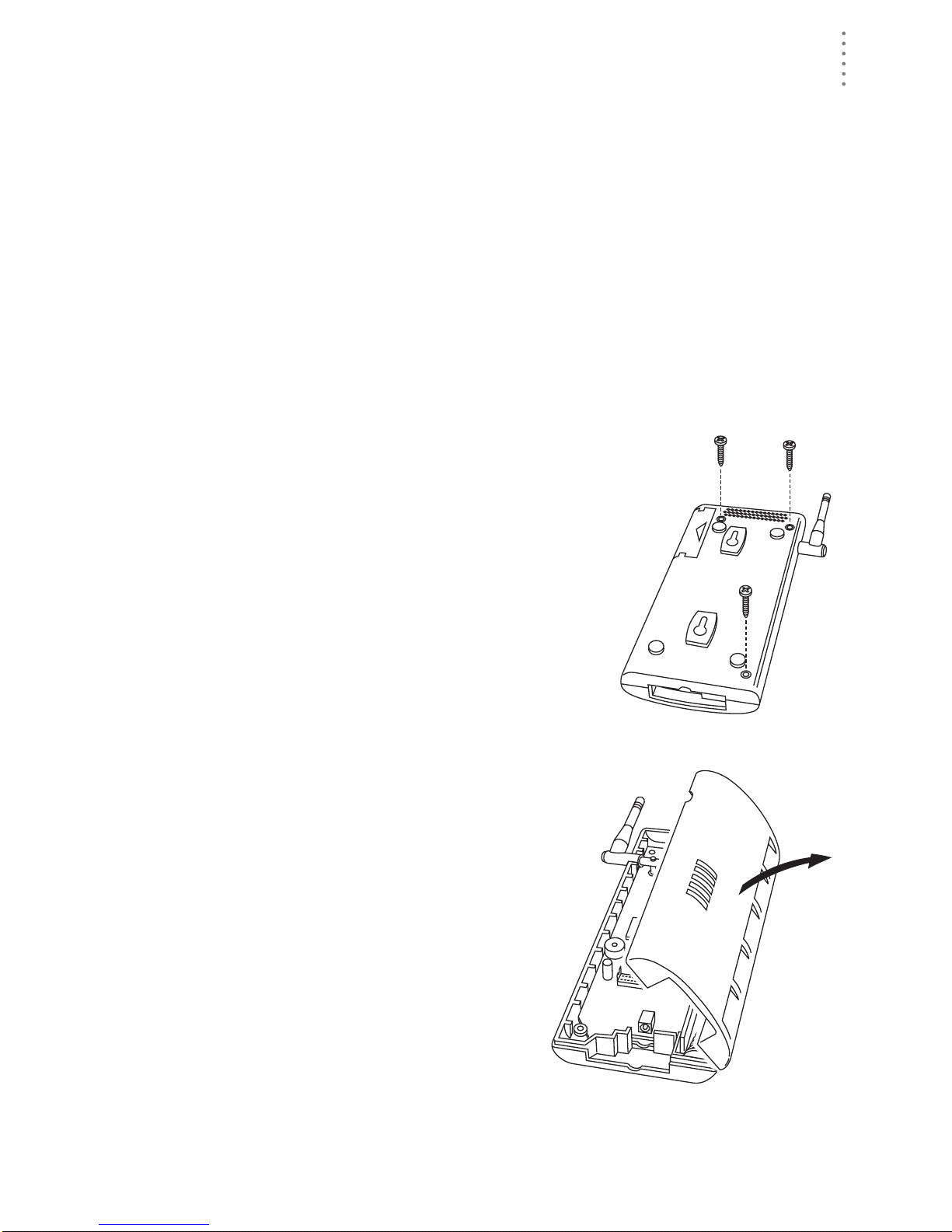
Installing the Data Logger
CAUTION: The WeatherLink data logger must be installed before you install the
batteries!
1. Remove the three screws from the back of the
Envoy case.
2. Separate the case halves to expose
the data logger connector.
3
Page 8
HARDWARE INS TALLATION
Preparing the Envoy
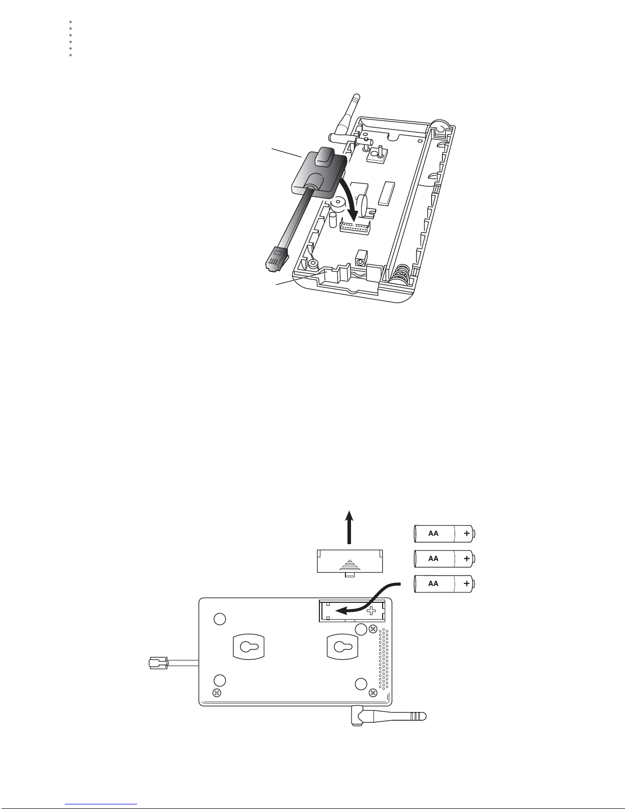
3. Carefully insert the data logger into the connector.
Note:Be sure to push down firmly on the data logger to seat the connection.
Data Logger
Data Logger Cable Channel
Installing the Data Logger
4. Rejoin the case halves, making sure the data logger cable passes through the
cable channel.
5. Fasten using the three screws you previously removed.
Installing the Batteries
CAUTION: The WeatherLink Data Logger must be instal led before you install the
backup batteries!
1. Find th e batte ry cover on the back side of the Envoy case.
2. Remove the battery cover by pressing on the arrow embossed on the cover
and sliding the cover away from the case.
4
Installing the Batteries
Page 9
HARDWARE INSTALLATION
Preparing the Envoy
3. Insert the three AA-c ell batteries, negati ve terminal (f lat side) fi rst.
The Envoy will run through a brief self-test procedure. If the test is successful
you will hear two (2) beeps.
4. Replace the battery cover on the case.
Note: Operating on battery power alone, the Cabled Weather Envoy will run approximately
10 days and the Wireless Weather Envoy will run approximately 5 months.
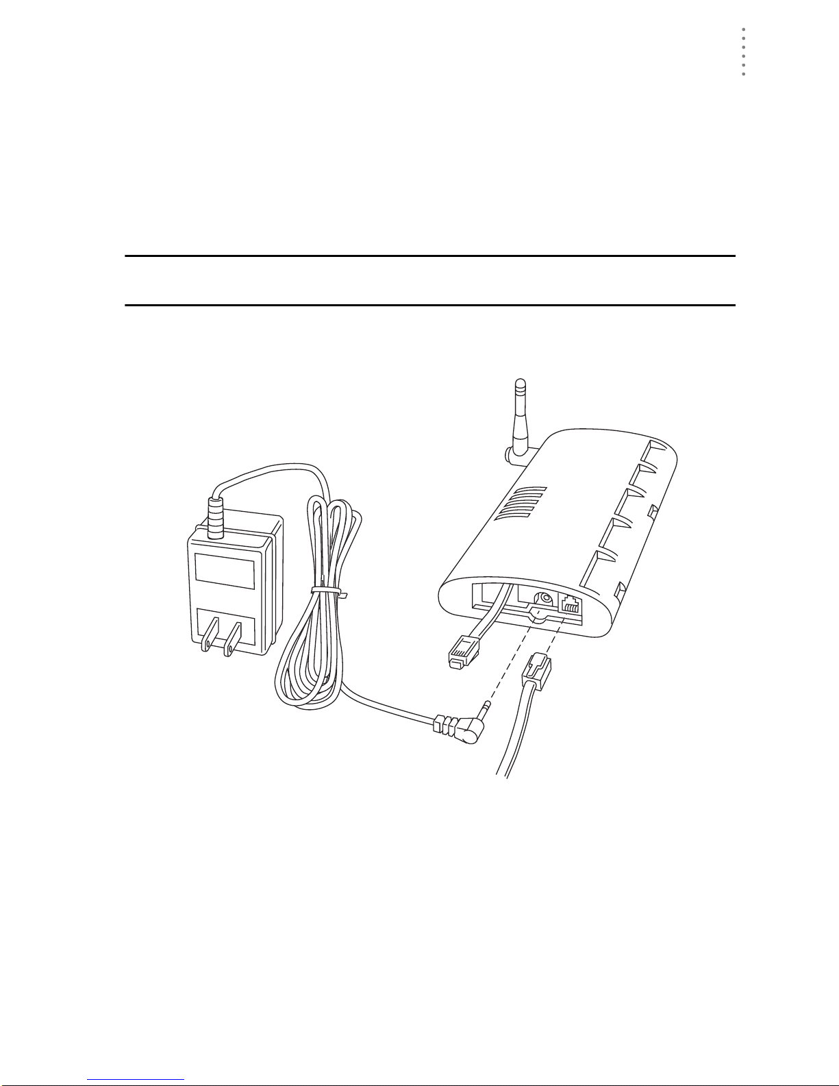
Connecting AC Power
CAUTION: The WeatherLink Data Logger and the backup batteries must be
installed before you connect AC power!
1. Locate the power adapter jack on the end of the Envoy case. It’s next to the
data logger ou tput cable.
Envoy
Data Logger
AC Power
Adapter
2. Insert the power adapter plug into the power jack.
Connecting a Cabled Envoy to the Inte grated Sensor Suite (ISS)
Refer to the figure shown in above “Connecting AC Power”.
1. Insert the modular plug into the ISS j ack on the Envoy cas e.
You won’t be able to tes t the connection between the Envo y and the ISS until
you have finished installing the WeatherLink software.
To
Computer
From Integrated
Sensor Suite
Power
Jack
Power, Sensor, and Computer Connections
(cabled models only)
5
Page 10

HARDWARE INS TALLATION
Preparing the Envoy
Mounting the Envoy
You can insta ll your Envo y on your desktop or on the wall next to you r compute r.
Note: Whenever you first install the Weather Envoy , place the antenna in a vertical position.
If necessary, you can adjust the angle for best reception after it’s installed.
Use this procedure for a wall installation.
1. Find the template located on the ne xt page.
2. Hold the template against the wall where you want to mount the Envoy, and
use a pencil to mark the location for the two mounting screws.
The screws should be 3.25” (82 .5mm) apart and lined up vert ically.
3. Drill the marked locations with a 3/32” or 7/64” ( 2.2 to 2.7 mm) drill bit.
4. Drive the two #6 x 1” (~ 3.5mm x 25mm) pan head self-threading screws into
the wall.
Leave at least a 1/8” (~ 3mm) space between the wall and the heads of the
screws.
5. Slide the keyholes on the back of the case over the two screw heads.
Wall Mounting the Weather Envoy
#6 x 1"
Pan-Head
Screws
Drill 3/32"
or 7/64"
(~2.2 to 2.7mm)
Holes
3.25"
(82.55mm)
Wall Mounting Template
6
Page 11
HARDWARE INSTALLATION
Local Computer Install ation
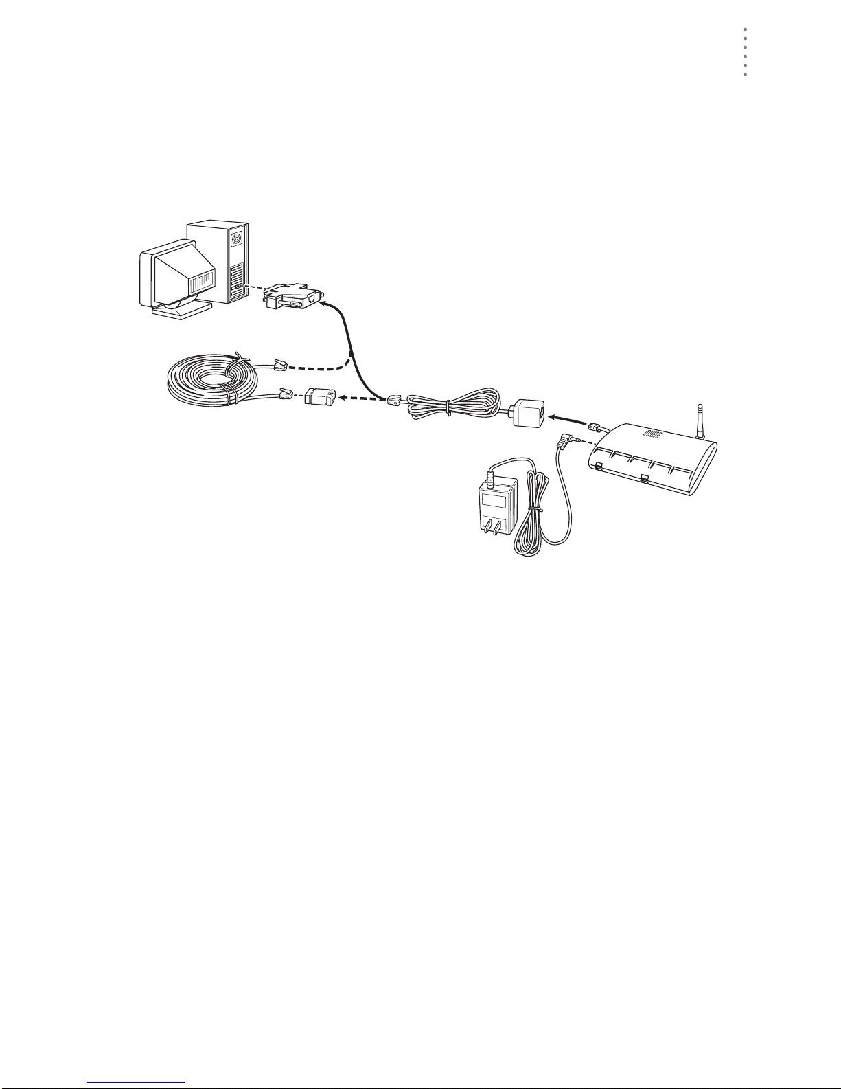
Local Computer Installation
The instructions below explain how to make a typical local connection. Note that
if you extend the cable run beyond 48’ (14.4 m), the software may have difficulty
communicating with the station.
Note: Mac Users - Refer to your WeatherLink for Mac OS X Getting Started Guide for addi-
tional installation instructions.
9-Pin
Connector
(DB-9)
Weather Envoy
Optional 40' (12 m) 4-Conductor
Extension Cable and Coupler
8' (2.5 m) Cable
Data Logger
AC Power
Adapter
Local Computer Installation
Installing with a Lo cal Com puter
1. Locate a free serial port on the back of your computer and connect the DB9 to
the port.
2. Insert the cable plug at the end of the shor t cable coming fr om the data log ger
into the receptacle on the end of the 8’ cable. Then insert the cable plug on the
end of the 8’ cable into the DB9 adapter.
The cable connecting the data logger to the computer is 8’ (2.4 m) long. If you
need to place the station cons ole more than 8’ from the computer, use a 40’ (12
m) standard 4-conductor extension cable (#7876 -040). Do not att empt to use
more than 40’ of extension cable, or the data logger may ha ve difficulty communicating with the computer .
Note: The Weather Envoy data logger does not need to be connected to the computer for
the logging to work. You can connect the cable to the computer when you’re ready to
download, then disconnect it if you want to place the Weather Envoy somewhere
else. However, the WeatherLink bulletin, summary, or real-time strip charts can be
displayed only while the Weather Envoy is attached to the computer.
7
Page 12
HARDWARE INS TALLATION
Remote Computer Installation
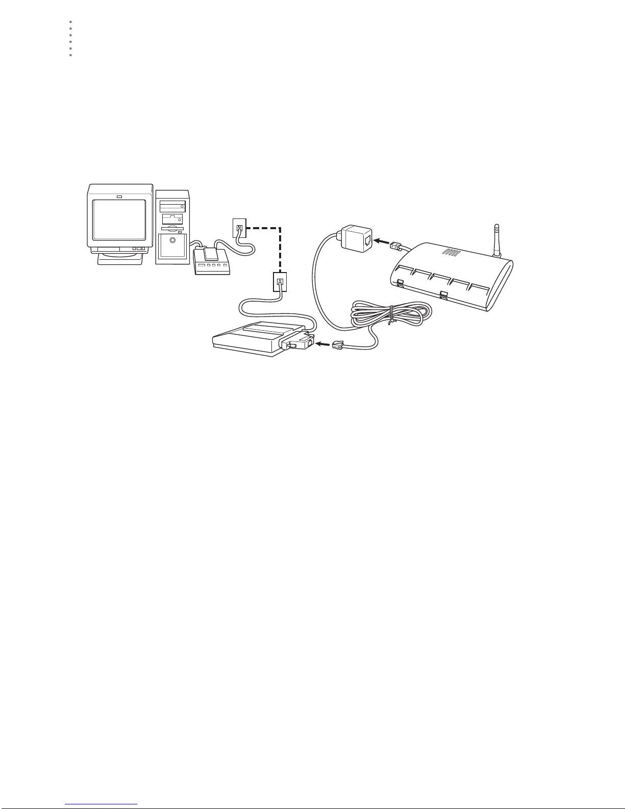
Remote Computer Installation
The illustration below shows a typical remote computer installation using a
modem. This involves connecting the data logger to the Weather Envoy and to a
modem at the station console site and connecting your computer’s modem to a
phone line, which will allow you to dial the Weather Envoy .
Note: Mac Users - Refer to your WeatherLink for Mac OS X Getting Started Guide for addi-
tional installation instructions
Weather Envoy
with Data Logger
Windows Computer
Note: Before installing the console and modem at a remote location, test the data logger
and connection first using a direct connection like that shown in the section above.
External or
Internal Modem
External
Modem
Remote Computer Installation
25-pin Telephone Modem
Adapter (#6533)
8 feet (2.5 m)
Data Logger Cable
(standard)
Remote Modem Connection Hardware Requirements
The following ad ditional hardware is required for a phone modem c onnecti on.
▲ One internal or external modem connected to your computer
The modem must be Hayes®–compati ble and run at 1200, 2400, 4800, 9600,
14400 or 19200 baud.
▲ One external modem to connect to the Weather Envoy data logger
The modem must be Hayes
14000 or 19200 baud.
®
–compati ble and run at 1200, 2400, 4800, 9600,
▲ Telephone Modem Adapter
The Telephone Modem Adapter (#6533) provides the connection between the
Weather Envoy data logger and the modem.
8
Page 13

HARDWARE INSTALLATION
Remote Computer Installation
Installing with a Remote Comput er
1. Ins tall a nd set u p an int ernal or exter nal m odem (acc or din g to th e instr uctio ns
supplied by the manufacturer) for use with your computer.
Make a note of the COM port used by the modem. You will need this informa-
tion when entering serial port settings for the station.
2. At the Weather Envoy site, put the external m odem in a location whe re it can
connect to both the data logger and the phone jack.
Note: Both the modem and the Weather Envoy should be powered down at this time, if they
are not already turned off.
The cable connecting the data logger to the modem is 8’ (2.4 m) long. If you
need to mount the station console more than 8’ from the modem, use a 40’ (12
m) standard 4-conductor extension cable. Do not attempt to use more than 40’
of extension cable, or the data logger may have difficulty communicating with
the modem.
3. Plug the external modem into the phone jack.
4. Co n ne ct the Weather Envoy data logger to the modem.
5. Power up the modem.
6. Power up the Weather Envoy last.
A Few Notes About Phone Modem Connection s
If you indicate a phone modem connection when setting up your station, the
software automatically dials the station whenever you initiate a program action
that req ui r es the software to ta lk to th e stat io n .
While connected to a phon e modem station, an “On-Line” icon appears in the
toolbar. This icon indicates that you are on-line and may be used to hang up a
remote connection. To hang up, click on the On-Line icon from the toolbar or
choose Hang Up from the File menu.
On-Line Icon
Toolbar with On-Line Icon
By default, WeatherLink will hang up the connection to the modem after o ne
minute without any commu ni cat ion wit h th e stat ion . Use th e Seria l Port dia log
box in the Setup menu of WeatherLink to change this default value. (See the
WeatherLink help files for more on this subject.)
Note: WeatherLink will not hang up the phone line if the Bulletin or Summary windows are
active.
9
Page 14

SOFTWARE I NSTALLATION AND SETUP
Installing the Software
Software Installation and Setup
Refer to the following procedure to install WeatherLink software on your
computer.
Installing the Software
Windows Computer
1. Pla ce the Insta ll Disk in your CD ROM drive.
2. The install program sh oul d st ar t au t om atic all y. If the in stall program does not
start, choose Run from the Start menu, ty pe D:\SETUP (or E:\SETUP, substituting the correct drive letter for D or E), and choose OK to begin the installation.
3. Follow the on-screen prompts to complete the installation.
Macintosh Computer
1. Pla ce the Insta ll Disk in your CD ROM drive.
2. Copy “install.sit” from the CD to your destop and open it.
The installation software will automatically extract itself.
3. Ru n “in st all”.
4. Follow the on-screen prompts to complete the installation.
Running the Software
To run the software, doub le-click on the WeatherLink icon. I f you have n o stat ions
in the program directory when you run the software, the software will prompt
you to add a station (see below for details). If you have more than one station in
the program directory when you run the software, the software will open the last
station accessed.
Station Setup
T o interact with your station, you must add your station to We atherLink’s database,
which means naming the station, configuring t he softwar e to work with th at station
and with your computer hardware, and setting station values such as time,
barometric pressure, total rainfall, and calibration numbers.
Adding a Station
1. Choose New Station from the File menu.
The software opens the Add New Station dialog box.
2. Type the station name into the text box.
The station name may be up to 40 characters/spaces long. Note that the soft-
ware uses the first eight characters of the station name (not counting spaces or
punctuation marks) as the name of the directory into which it saves this station’s database and configuration files. The first eight characters of each station name must, therefore, be unique.
10
Page 15

SOFTWARE I NSTALLATION AND SETUP
Station Setup
3. Choose OK.
The software saves the station, creates a directory and subdirectories for that
station, and prompts you to indicate whether you want to enter the walkthrough procedure.
About the Walkthrough
The software includes a “Walkthrough” utility t ha t ste ps you t hrough most of the
station setup and configuration procedures. After adding a new station, the software automatically asks you whether or not you want to be walked through the
configuration procedure. You can, of course, choose No and set up the station by
choosing all of the necessary commands from the menus. A Walkthrough command is included in the Setup menu that lets you begin this procedure at any
time.
Note: If you have a remote computer connection, then the software will automatically dial a
phone modem station when it is necessary.
Note: Mac Users - Your Walkthrough will be a little different. Please refer to your Weather-
Link for Mac OS X Getting Started Guide for Walkthrough information.
If you choose Yes to begin the Walkthrough, the software takes you through the
following dialog boxes:
▲
Sta tion Configuration
Set station name, model, accessories, download options, and data file
extension.
Serial Port Settings
▲
Set COM port to which data logger is connected. Specify modem connection settings such as baud rate, phone number, and modem initialization
string.
Configur e C onsole
▲
Use the Configure Console dialog box to set the DavisTalk transmitter ID
assignments, turn on and off the console retransmit function, set daylight
savings time, select start of the rain season, and enable or disable averaging of temperatures over the archive period.
▲ Choose Units
Select units of measure in which station information is displayed.
▲
Set Barometer & Elevation
Set the barometric pressure and your elevation on the station and on the
software.
▲
Set Rain Calibration
Set the station’s rainfall calibration number.
▲
Set Temperature and Humidity Calibration
Adjust the temperature and humidity settings on your station if necessary.
▲
Enter Year-to-Date Rainfall
Set the rainfall amount on the station and on the software. You must enter
this information from the software if you want you station and software
readings to agree.
Set Time and Date
▲
Set the time and date on the station, software, and computer and make
sure all three are synchronized.
11
Page 16

SOFTWARE I NSTALLATION AND SETUP
Station Setup
Note:When you set the time and date, yo u w i ll be prompted to clear your archive memory.
If you do not clear archive memory, you may end up with data stored at an incorrect
time or duplicate re cords. We recommend that you download before setting the time,
unless you are creating a brand new station or just adjusting the time, so you may
safely clea r t he archive memory.
▲ Set Archive Interval
Set the interval at which data will be stored in the data logger’s memory.
This will clear any data stored in the data logger.
▲
Set Latitude and Longitude
You must set the correct latitude and longitude for the station’s forecast,
moon phase, and sunrise and sunset algorithms to work correctly.
▲
Set Station Alarms
Set alarm thresholds on the station.
▲
Set Auto Download Time(s)
Specify the stations and the times at which you want data automatically
downloaded to your computer each day.
At each step in the Walkthrough procedure, the software will provide confirmation boxes prompting you to indicate w he ther or not you wi sh to continue. To
continue, choose OK. To skip any step and move to the next, choose Skip. To cancel the entire Walkthrough procedure, choose Cancel.
New Station
Each station connected to the computer must have its own “station” withi n the
software. This tells the software into which database new data should be saved,
provides the necessa ry co mmun ic at ion set tings (ser ial port , e tc.), an d other
station-specific inform ation.
1. Choose New Station from the File menu.
The New Station dialog box appe ars.
New Station
2. To add a station, type the desired station name (up to 40 characters/spaces)
into the Station Name text box and choose OK.
The software saves the station, creates a directory for that station using the
first eigh t characters in the station name (not i ncluding punctuation and
spaces), and prompts you to indica te whether you want to ent er th e Walkthrough procedure (see “About the Walkthrough” on page 11).
12
Page 17

SOFTWARE I NSTALLATION AND SETUP
Station Configuration
You may enter information which will help to identify a particula r sta t ion and
select a number of station-specific settings.
1. Choose Station Config from the Setup menu or press Ctrl-C.
The Station Configuration dialog box appears.
Station Setup
Station Configuration
2. Enter the following information:
▲
Name
Enter the desired station name in this text box. Note that when you first
create a station, the software uses the first eight characters of th e s tation
name as the name of the directory into which it saves this station’s database and configuration files. If you change the station name, the software
will prompt you to change the name of the station directory.
Model
▲
Select the weather station model from the drop-down list. Select “Vantage
Pro” or “Vantage Pro Plus” if the list does not include “Envoy”.
▲ Rain Collector
Select the increment in which the rain collector you use with the station
measures rainfall. If you do not have a rain collector, choose None.
▲
Optional Accessories
Check each of the listed optional sensors that ar e insta lled in your wea ther
station.
▲ Download Options
The software can automatically create a space-delimited text file containing two-days worth of data records after each download. To enable this
feature, check the box. The file is na me d “downloa d.t xt ” an d is saved int o
the station directory.
13
Page 18

SOFTWARE I NSTALLATION AND SETUP
Station Setup
Note: The “download.txt” file is written as a space-delimited file. The export feature avail-
able in the Browse Window produces a tab-delimited file.
3. When finished, choose OK.
The software saves the station configuration settings.
Serial Po rt
To co mmunicate with the data logger and station you must select the serial port
you are using and enter the correct settings.
1. Choose Serial Port
from the Setup
menu or press CtrlI.
The Serial Port Settings dialog box
appears.
2. Enter the following
information:
▲
Serial Port
Select the seri al
port to which
the data logger
or modem is
connected.
Baud Rate
▲
Set the baud
rate to 19200, the default baud rate for the Weather Envoy Data Logger.
▲ Hangup Wait Time
Enter the amount of time, in minutes, the program should wait before
hanging up the conne ction and r elea sing th e serial port durin g an idle connection. If, for exampl e, you’ve di aled your sta tion, do wnload ed data , and
then left the connection open without the bull eting or summary running,
the software wi ll ha ng u p the modem after the time you spec ify he r e. This
feature is useful if another program uses the modem or another program
accesses the data logger.
Dial Up Connection
▲
Select this che c k box to connec t to the Weather Envo y by modem (remote
connection). Once you’ve selected this box, the grayed-out options in the
lower part of the dialog box will be activated.
Weather Station Ph one Number
▲
Enter the phone number for the modem connected to the station (Weather
Envoy) in this box. Make sure to enter the area code and any necessary
prefixes (for example, 1, 011, etc.).
Serial Port
▲ Enter a comma (,) to force the modem to pause before dialing the next
digit. You may enter more than one comma to increase the length of
time for which the modem pauses.
▲ Enter a “w” to force the modem to wait for a dial tone before dialing
the next digit.
14
Page 19

SOFTWARE I NSTALLATION AND SETUP
Station Setup
▲ Modem Initialization String
The default modem initialization string should work in almost all cases:
AT &F S7=60 E Q V X4. Before changing the modem string, see “Modem
Initialization S tring” on page 34 for an e xplanation of what ea ch part of the
string means.
▲ After Connect Wait
Controls the number of seconds the software waits after it has connected
to a remote station before sending the first command. If you are having
difficulty connecting to a remote statio, try increasing the wait time.
▲
Rotary Dial
Select this che ck box if you are have a remote connection to the station by
modem using a phone modem connection and your phone is rotary dial.
3. When finished selecting options, choose Test.
The software will check the connection to the station (or modem) using the
current settings and indicate whether or not it successfully connected to your
Weather Envoy. If you cannot connect to the station, you may use L oopback
(see “Finding the Correct Serial Port” on page 33) to determine the correct
serial port or make sure the serial port itself is actually working.
4. Once the serial port settings are correct, choose OK.
The software saves the serial port settings.
Configure Console
Use the Configure Console
dialog box to set the DavisTalk transmitter ID assignments, turn on and off the
Weather Envoy retransmit
function, set daylig ht savings time, select start of the
rain season, and enable or
disable averaging of temperatures o v er the archiv e
period.
1. Choose Configure Console
from the Setup menu.
The Serial Port Setting s di a-
log box appears.
2. Set the Station Types
Select the station type used
by each of the DavisTalk
transmitter IDs.
Cabled Weather Envoys
▲
must have Station No. 1
set to ISS.
▲ If you are using a Temp/
Hum stati on a nd no ISS,
select Temp/Hum (ISS).
▲ You can select CLEAR ALL to set all transmitters to Off.
Configure Console
15
Page 20

SOFTWARE I NSTALLATION AND SETUP
Station Setup
3. Set Retransmit
If you want your Weather Envoy to retransmit weather data, say to either a
Vantage Pro console or a Weather Echo, turn Retransmit ON by selecting the
transmitte r ID number for t he retransmitted si gnal.
4. Set Daylight Savings
Select your local time zone from the list.
You can manually turn on Daylig ht Savings b y selecting On . If you select Auto
Detect Daylight Saving s, dayl ight savings time will automatic a lly turn on at
1 am on the first Sunday in April and turn of f at 2 am on the last Sunday in
October, or will turn off the last Sunday in March in Europe and Australia. If
neither On or Auto Detect Daylight Savings are selected, Daylight savings is
set to off.
5. Set Rain Season Start
Enter the date on which to start the annual rain totals. The rain season will
start on the fi rst day of the month you select.
6. Set Average Temp Over Archive Period
The defalt is to log the temperature at the end of the archive period.
7. When finished configuring the console, choose Set.
The software sets the alarms on the station console to match the settings in this
dialog box.
Select Units
You may select the units of measure in which data is displayed within the
software. All program windows (bulletin, summary, plots, database, etc.) display
data in the selected units of measure.
1. Choose Select Units from the Setup menu or press Ctrl-U.
The Choose Units dialog box appears.
2. Select the desired units of measure:
▲
Temperature: Fahrenheit (°F) or Celsius
(°C)
Wind chill, dew point, degree-days,
and heat index a re all displ ayed in the
same unit of measure as temperature.
Barometer: Inches of Hg (in),
▲
Millimeters of Hg (mm), Millibars (mb),
or Hectopascals (hPa)
▲ Wind Speed: Miles per Hour (mph),
Knots (knot), Kilometers per Hour (km/
hr), or Meters per Second (m/s)
▲ Rain: Inches (in) or Millimeters (mm)
Rain and ET use the same units of
measure.
▲
Elevation: Feet (ft) or Meters (m)
Choose Units
16
Page 21

SOFTWARE I NSTALLATION AND SETUP
Station Setup
3. After selecti ng units of measure, choose OK.
The software sa ves your cho ices. All informa tion will b e displayed in the units
of measure you selected.
Set Barometer
You configure the barometer by entering the Weather Envoy’s current elevation
and current barometric pressure. If you don’t know the elevation, there are many
ways to find out. For example, you can try calling the reference desk at your local
library, looking up your town in an almanac, or calling the local airport. In the
USA you can look at a United States Geological Survey topographical map of
your area.
Here are a few on-line res our ces for find ing your elev ation :
http://www.topozone.com/ (US only)
▲
▲ http://www.calle.com/world/ (Outside US only)
1. Choose Set Barometer from the Setup menu.
The software opens the Set Barometer dialog
box.
2. Enter the elevation
The elevation is required for the forecast to
work correctly and to report the adjusted
baromtric pressure.
3. Enter the correct sea-level barometeric pres-
sure.
Note: Only enter this if you have a current reading from
a very reliable nearby reference. Do not use the
Sea-level Barometer setting alone to correct your
barometer to sea-level.
Set Barometer
For the most accurate barometer readings, enter a "Sea-level Barometer" pressure from a reliable nearby reference. The Weather Envoy uses this value to
calibrate it’s own adjusted barometric pressure calculations. The software
saves the change in barometric pressure in the Weather Enovy and in the
WeatherLink station configuration file.
Note: If you set the Sea-Level Barometric pressure to 0, the bar calibration number is
erased. The station will display the pressure reading altered by the station elevation
only.
17
Page 22

SOFTWARE I NSTALLATION AND SETUP
Station Setup
Set Rain Cal
Based on the type of rain collector you selected in station configuration (See
“Station Configuration” on page 13), the software automatically changes your
station console’s rainfall calibration number to the correct setting.
1. Choose Set Rain Cal from the Setup
menu.
The software prompts you to confirm
that you wish to change the rainfall calibration number.
2. Choose Yes.
Remote Computer Installation
The software set s the rainfall calibr ation
number on your station.
Set Temp & Hum Cal
If you need to adjust your temperature and humidity readings, you can change
the console the temperature calibration numbers using WeatherLink.
1. Choose Set Temp Hum Cal from the Setup menu.
The Set Temp Cal dialog box
appears. The raw readin g show n in
this dialog box indicates the unadjusted reading coming fro m the sensor. The adjusted reading indicates
what the so ftware displays,
adjusted for any pr eviously enter ed
calibration number.
2. Enter the adjusted reading for the
variable you want and choose OK.
The software updates the station’s
calibration numbers. The station
and software will accept temperature adjustments up to ±12.7 ºF (~
7.1 ºC) away fro m t he raw reading.
For example, if Weather Envoy is
recording an inside temperature
reading of 60º F (15.6 ºC), you coul d set the temperature anywhere between
47.3ºF (8.6 ºC) and 72.7ºF (22.6 ºC). (60-12.7=47.3, 60+12.7=72.7)
Set Temp & Hum Cal
Note: Weather Envoy minimum and maximum temperature settings are –90ºF and +164ºF.
The Weather Envoy accepts humidity calibrations between 0 and 100%.
Yo u can use the Clear dialog box to reset all temperature and humidity cal i-
bration numbers at once.
18
Page 23

SOFTWARE I NSTALLATION AND SETUP
Station Setup
Set Total Rain
You may want to enter a total rainfall amount to reflect any rainfall which
occurred during this season before you obtained your station or before you
started using the software.
1. Choose Set Total Rain from the
Setup menu.
The Set Total Rain dialog box
appears.
2. Enter the total rainfall amount
and choose OK.
The software saves the total
rainfall amo un t to th e cons o le
Set Total Rain
and to the station’s configu r at ion file.
Set Time
Yo u may set the time and date on your Weather Envoy and your computer from
the software. It is important to mak e sure that both the Weather Envoy and
computer use the same time and date. Because changing time and date on the
station can affect data in the WeatherLink’s archive memory, we recommend that
you download data before setting the time and date and then clear your archive
memory when finished.
Note: The Weather Envoy internal clock is more accurate than most computer clocks. We
recommend you double-check the correct time from a source other than your computer.
1. Choose Set Time from the Setup
menu.
The Set Time & Date dialog box
appears. The time an d date cur rently displayed by the station
console appear at the top of the
dialog box. The software automatically enters the time and
date displayed by the computer
into the text b oxes a t the bot tom
of the dialog box.
2. Enter the following information:
Time/Date
▲
Set Time & Date
Enter the current time and/or date.
▲
Set the PC time also
If you want the so ftware to set the ti me and date on bo th the station console and the computer, select this check box.
3. After entering time and date, cho ose OK.
The software sets the time and date on the station console (and the PC) and
then prompts you to indicate whether you want to clear your archive memory
as well.
19
Page 24

SOFTWARE I NSTALLATION AND SETUP
Station Setup
4. To indicate whether you want to clear your archive memory , choose Yes or No.
If you choose Yes, the software clears your archive memory.
Set Archive Interval
You may choose to store data to the WeatherLink’s ar c h ive memory at an interv al
of 1, 5, 1 0, 15 , 30, 60, or 120 minu tes. T his interv al is kn own as t he archive inte rval .
Look for information on archive memory and the effect that the archive interval
has on the amount of data which may be stored in the WeatherLink’s archive
memory in the WeatherLink software Help.
Note: Setting the archive interval clears your archive memory. You should download data
before changing archive interval.
1. Choose Set Archive Interval from the Setup
menu.
The Set Archive Inte rv al dia log box appe ar s.
2. Select the desired archive interval and choose
OK.
The software warns yo u that it is about t o clear
the archive memory.
3. To continue, choose OK.
The software sets the archive interval and
clears the archive memory.
Set Archive Interval
Set Latitude and Longitude
To give you the best forecast, to calculate the correct times for sunset and sunrise
for your location, you must set the latitude and longitude in the console.
1. Choose Set Latitude/Longitude from the Setup menu.
2. Enter the following information:
Latitude
▲
Enter the current latitude in degrees, minutes and seconds and indicate if
the position is in the Northern or Southern hemi sphere.
Longitude
▲
Enter the current longitude in degrees, minutes and seconds and indicate
if the position is in the East or West of the Prime Meridian.
3. Click on See Results to check the latitude and longitude settings that will
transfered to th e En voy. These are t he sa me set ti ngs you en tered, but rounded
to the nearest tenth of the de gree.
4. When you are satisified with the settings, choose OK.
20
Page 25

SOFTWARE I NSTALLATION AND SETUP
Station Setup
Set Latitude and Longitude
Note: Note:Latitude and longitude are a way of identifying your position on the earth. Lati-
tude measures distance north or south of the equator. Longitude measures distance
east or west of the Prime Meridian, an imaginary line running north and south through
Greenwich, England.
If you do not know your lati tu de a nd long it ud e, th ere are many ways to find out.
Many atlases and maps include latitude and longitude lines. You can also talk to
the reference department of your local library, or try calling your local airport. If
you are installing your station in the United States, the US Geological Survey
(USGS) produces topographic maps with elevations. The more accurate you are,
the better; however; a reasonable estimate will work, too.
Here are some on-line resources for finding your latitude and longitude:
http://www.geocode.com/eagle.html-ssi
▲
▲ http://www.topozone.com/ (US only)
▲ http://www.calle.com/world/ (Outside US only)
This dialog box includes text boxes to input your position. You can enter your latitude and longitude as degrees, minutes, and seconds, or as fractions of a degree.
For example, Hayward, California, the home of Davis Instruments, lies at approximately 37 degrees 38 minutes 10 seconds north of the equator and 122 degrees 7
minutes and 30 seconds west of the Prime Me ridi an .
You could also enter the latitude and longitude in decimal form by putting 37.6 in
the first box for the latitu de and 122.1 in the first box for the longi tude and leavi ng
the other boxes blank.
The dialog box also show s what the station ’s curr ent settin gs ar e. You can use this
dialog box to set th e latitude and lon gitude for the NOA A reports , the sunrise a nd
sunset calculations, and APRS weather reports even if the weather station is not
connected to the PC. See the Reports section for more info.
21
Page 26

SOFTWARE I NSTALLATION AND SETUP
Station Setup
Set Alarm s
Yo u may quickly set the alarm thresholds on the Weather Envoy using the
software. See the Alarms section in this manual for more information on alarms
and how they w ork.
Note: The only way to clear an alarm in the Weather Envoy is to modify the threshold in the
Alarm Setup screen to a value that would not cause an alarm, or to delete the value
altogether.
1. Choose Set Alarms from the Setup menu or press Ctrl-A.
The Set Stati on Alarms dialog box appears.
2. Enter the following information:
▲
High/Low Alarm
For all standard high/low alarms, enter the desired alarm threshold into
the text box.
To clear an alarm, clear the contents of the text box or enter two (2) dashes:
"--".
▲ Barometer
Enter the 3-hour low (fall) and /or high (rise) pressure trend thresholds.
To clear an alarm, clear the contents of the text box or enter two (2) dashes:
"--" (two dashes).
▲
Time
Enter the time for the alarm in the text box. To clear the alarm, clear the
contents of the text box or enter two (2) dashes: "--".
22
Set Station Alarms
Page 27

SOFTWARE I NSTALLATION AND SETUP
Station Setup
3. When finis hed ent eri ng alarm infor mat ion, choose Set.
The software sets the alarms on the station console to match the settings in this
dialog box.
Auto Download
You may set up the software to automatically download data at specified times
each day (the software must be running).
1. Choose Auto Download from the Setup menu or press Ctrl-J.
The Auto Download dialog box appears. The stations which appear in the
Auto Download List will be downloaded automatically.
Set Auto Download
2. To add a station to the Auto Do wn lo ad List, double-click on the station name
or select the station from the Station Names list and choose Add.
The station name will be moved to the Auto Download List. You may select
more than one station before choosing Add to add several stations at once.
You may quickly add all stations in the Station Names list by choosing Add
All.
3. To remove a station from the Auto Download List, select the station and
choose Remove.
The station name will be removed from the Auto Download List. You may
select more than one station before choosing Remove to r em ove sev era l sta tions at once. You may quickly remove all stations in the list by choosing
Clear.
23
Page 28

ALARMS
Station Setup
4. To set the time(s) at which the selected station should be downloaded, choose
Download At.
The Download At dialog box appears.
5. Enter the following information:
▲ Download Times
Select the hour(s) at which the software should automatically download information fr om this s tation by
clicking on the desired hour in the
list. You may select as many download hours as you want; the software
will download data from your station during each of the specified
hours. To de-select a previously
selected hour, click on it again. To
quickly select all hours, choose
Choose All. To quickly clear all
selected hours, choose Clear.
Offset Time
▲
To force the software to automatically download a specific number of
minutes after the selected hour(s), enter the number of minutes here. For
example, in the illustration above the software would automatically
download at 8:05 and 9:05 am.
Set Download Times
6. After setting the download time(s), choose OK.
The software sa ves the automatic download time settings.
Alarms
The Weather Envoy features more than 30 alarms th at can be programmed to
sound whenever a reading exceeds a set value. With the exception of barometric
pressure and time, all alarms sound when a reading reaches the alarm threshold.
For example, if the high outside temperature alarm threshold is set at 65 ºF, the
alarm will sound when the temperat u re rises to 65.0 ºF.
Low alarms work t he sa m e wa y. For example, if th e win d c hil l th reshold is set for
30 ºF, the alarm begins sounding when the temperature drops to 30.0 º and will
continue until the temperature again rises above 30.0º.
If you’re on battery power, the alarm will sound for two minutes only. If you’re
using the AC adapter, the alarm will continue as long as the condition exists. The
alarm will also sound again for each new alarm.
T o silence a sounding alarm, edit the Alarm set up screen to either delete the al arm
threshold or to m odi fy t he t hreshold so that the curr ent conditions don’t cause a n
alarm.
24
Page 29

Three specia l alarms
▲ ETo (Evapotranspiration)
ETo is updated only once an hour, on the hour. If during a given hour the
ETo Value exceeds the alarm thres hold, the ETo alarm sounds at the end of
that hour. This is true for daily, monthly, and yearly ETo alarms. You must
have the optional Solar Radiation Sensor to use this alarm.
▲ Barometric Pressure
The Weather Envoy allows you to set two barometric pressure alarms: a
“rise” alarm and a “fall” alarm. Y ou may select any rate of change per hour
between 0.01 to 0.25 in Hg (0. 1 to 6.4 mm Hg, 0.1 to 8. 5 hPa/mb ); the
alarm will sound if the rate of change (in the selected direction) exceeds
the thres ho ld you set.
▲
Time
The time alarm is a standa r d “alar m clock” ala rm. It w ill sound at t he time
you’ve set. Make sure you choose am or pm, if you’re in 12-hour mode. It
will sound for one minute.
WEATHER DATA MEASURED & C ALCULATED
Wind
Weather Data Measured &
Calculated
This section outlines each of the weather conditions measured and/or calculated
by the Weather Envoy, by the Vantage Pro Integrated Sensor Suite (ISS), and by
optional Vantage Pro sensors. Each section includes a brief discussion of the
weather condition and a listing of the various ways in which the unit displays or
stores that condition. Be aware that some of the weather conditions require an
optional sensor in order to measure or calculate a value.
Wind
The anemometer measures wind speed a nd the direction fr om which it’s blowin g.
Temperature
The Weather Envoy uses the ISS’s temperature sensor to measure the outside air
temperature. A second temperature sensor in the Weather Envoy measures the
inside air temperature. Additional temperature sensors (available only with
wireless Vantage Pro and Weather Evnoy systems) can be used to measure
temperature in other locations. You may use these extra sensors to measure any
other temperatures that are within the sensor’s range, including liquids such as
water.
Apparent Temperatures
The Weather Envoy calculates three apparent temperature readings: wind chill,
heat index, and the temperature/humidity/wind index (THW Index).
25
Page 30

WEATHER D ATA MEASURED & CALCULATED
Humidity
▲ Wind chill
Wind chill takes into account how the speed of the wind affects our perception of the air temperature. Our bodies warm the surrounding air molecules by transferring heat from the skin. If there’s no air movement, this
insulating layer o f warm air molec ules st ays next to the body and offers
some protection from cooler air molecules. However, wind sweeps that
comfy warm air surrounding the body away. The faster the wind blows,
the faster heat is carried away and the col der you fee l.
Wind chill is not stored in arc hi ve mem ory. Wind chill is calculated whenever it is displayed. If you edit temperature or wind speed values, the
wind chill will change as well.
Note:WeatherLink versions 5.1 and lat er use the Osczevski (1995) equ at i on t o calcu-
late wind chill. This is th e method adopted by the US Nati onal Weather Service in
September of 2001.
▲ Heat Index
The Heat Index uses the temperature and the relative humidity to determine how hot the air act u all y “feels.” When humidity is low, the apparent
temperature will be lower than the air temperature, since perspiration
evaporates rapidly t o c ool t he b ody. However, when humidity is high (i.e.,
the air is saturated with water vapor) the apparent temperature “feels”
higher than the actual air temperature, because perspiration evaporates
more slowly.
THW (Temperature - Humidity - Wind)
▲
Finally, like Heat Index, t he TH W Ind ex use s humi dity and temper atur e t o
calculate an apparent temperature, but includes the cooling and heating
effects of wind on our perception of temperature.
Humidity
Humidity itself simply refers to the amount of water vapor in the air. However,
the amount of water vapor that the air can cont ain varies with air temperature
and pressure. Relative humidity takes into account these factors and offers a
humidity reading which reflects the amount of water vapor in the air as a
percentage of the amount the air is capable of holding. Relative humidity,
therefore, is not actua lly a measure of the amount of water vapor in the air, but a
ratio of the air’s water vapor content to its capacity. When we use the term
humidity in the manual and on the screen, we mean relative humidity.
It is important to realize that relative humidity changes with temperature, pressure, and water vapor content. A parcel of air with a capacity for 10 g of water
vapor which contains 4 g of water vapor, the relative humidity would be 40%.
Adding 2 g more water vapor (for a total of 6 g) would change the humidity to
60%. If that same parcel of air i s then warmed so that it has a cap acity for 20 g of
water vapor, the relative humidit y dr ops t o 30% even thoug h water vapor c ontent
does not change.
Relative humidity is an important factor in determining the amount of evaporation from plants and wet surfaces since warm air with low humidity has a large
capacity for extra water va por.
26
Page 31

WEATHER DATA MEASURED & C ALCULATED
Dew-Point
Dew-point is the temperature to which air must be cooled for saturation (100%
relative hum idi ty) to oc cur, providing there is no chan ge in water cont ent . The
dew-point is an important measurement used to predict the formation of dew,
frost, and fog. If dew-point and temperature are close together in the late
afternoon when the air b egins to turn colder, fog is likely during the night. Dewpoint is also a good indicato r of the air’ s actual water vapor content, unlike
relative humidity, which take s the air’s temperature into account. H igh dew-point
indicates high vapor content; low dew-point indicates low vapor content. In
addition a high dew-point indicates a better chance of rain and severe
thunderstorms. You can even use dew-point to predict the minimum overnight
temperature. Provided no new fronts are expected overnight and the afternoon
Relative Humidity ≥ 50%, the afternoon’s dew-point gives you an idea of what
minimum temperature to expect overnight, since the air is not likely to get colder
than the dew-point anytime during the night.
Rainfall
Four separate registers track rainfall totals: “rain storm”, “daily rain”, “monthly
rain”, and “yearly rain”. The Weather Envoy also calculates the rate of rainfall by
measuring the interval of time between each .01 in or 0.254 mm rainfall increment.
The rain collector physically m easure s incr ements of 0.0 1 in. If you display in mm,
the console converts from inches to mm. If you display millimeters, you may
occasionally see the counter skip a reading due to rounding.
Dew-Point
Barometric Pressure
The weight of the air that makes up our atmosphere exerts a pressure on the
surface of the earth. This pressure is known as atmospheric pressure. Generally,
the more air above an area, the higher the atmospher ic pr essure, this, in turn,
means that atmospheric pressure changes with altitude. For example,
atmospheric pressure is greater at sea-level than on a mountai ntop. To
compensate for this difference and facilitate comparison between locations with
different altitudes, atmospheric pressure is generally adjusted to the equivalent
sea-level pressure. This adjusted pressure is known as barometric pressure. In
reality, the Weather Envoy measures atmospheric pressure. When you enter your
location’s altitude in Setup Mode, the Weather Envoy stores the necessary offset
value to consistently translate atmospheric pressure into barometric pressure.
Barometric pressure also changes with local we ather conditions, maki ng b a r om et ric pressure an extremely important and useful weather forecasting tool. High
pressure zones are generally associated with fair weather while low pressure
zones are generally associated with poor weather. For forecasting purposes, however, the absolute bar ometric pressure value is generally less important th an the
change in barometric pressure. In general, rising pressure indicates improving
weather conditions while falling pressure indicates deteriorating weather conditions.
27
Page 32

WEATHER D ATA MEASURED & CALCULATED
Solar Radiation
Solar Radiation
Note: Requires optional solar radiation sensor (#6450, included on Vantage Pro Plus
weather stations).
What we call “current solar radiation” is technically known as Global Solar
Radiation, a measure of the intensity of the sun’s radiation reaching a horizontal
surface. This irradiance includes both the direct component from the sun and the
reflected component from the rest of the sky. The solar radiation reading gives a
measure of the amount of solar radiation hitting the solar radiation sensor at any
2
given time, expressed in Watts /sq. m (W/m
Note:The solar radiation sensor measures energy received in the spectral band between 400 and
1100 nm.
).
UV (Ultra Violet) Radiation
Note: Requires optional UV sensor (#6490), included on Vantage Pro Plus weather sta-
tions.
Energy from the sun reaches the earth as visible, infrared, and ultraviolet (UV)
rays. Exposure to UV rays can cause numerous health problems, such as sunburn,
skin cancer, skin aging, and cataracts, and can suppress the immune system. The
Weather Envoy can help analyze the changing levels of UV radiation and can
advise of situations where exposure is particularly unacceptable.
CAUTION: Be aware, however, that the UV sensor readings do not take into
account UV reflected off snow, sand, or water, which can significantly
increase the amount of UV to which you are exposed. Nor do the
readings take into account the dangers of prolonged exposure to UV
radiation. The r e a dings do not suggest that an y amount of exposure is
safe or healthful. Do not use the UV readings to determine the amount
of UV radiation to which you expose yourself. Scientific evidence
suggests that UV exposure should be avoided and that even low UV
doses can be harmful.
WeatherLink displays UV readings in two scales: UV, which is the amount of UV
radiation usin g the UV Index scale, a nd U V Dose , which display s an a ccumula ted
UV in MEDs.
MED stands for Minimum Erythemal Dose, defined as the amount of sunlight
exposure necessary to induce a barely perceptible redness of the skin within 24
hours after sun exposure. In other words, exposure to 1 MED will result in a reddening of the skin. Because different skin types burn at different rates, 1 MED for
persons with very dark skin is different from 1 MED for persons with very light
skin.
Both the U.S. Environmental Protection Agency (EPA) and Environment Canada
have developed skin type categories correlating characteristics of skin with rates
of sunburn. Tables 3a and 3b below list these skin types.
28
Page 33

WEATHER DATA MEASURED & C ALCULATED
UV (Ultra Violet) Radiation
TABLE A1: EPA SKIN PHOTOTYPES
SKIN PHOTO-
TYPE
1 - Never tans,
always burns
2 - Sometimes
tans, usuall y
burns
SKIN COLOR TANNING & SUNBURN HISTORY
Pale or milky white;
alabaster
Very light brown;
sometimes freckles
Develops red sunburn; painful
swelling, skin peels
Usually burns, pinkish or red coloring appears;
can gradually develop lig ht brown
tan
3 - Usually tans,
sometimes
burns
4 - Always tans;
rarely burns
Light tan; brown, or
olive;
distinctly pigmented
Brown, dark brown,
or black
Rarely burns; shows moderately
rapid tanning response
Rarely burns; shows very rapid tanning response
T. B. Fitpatrick of the Harvard Medical School developed a categorization of skin
types 1 through 6 which were adopted by Environment Canada. These skin types
are detailed in Table 3b below.
ABLE A2: ENVIRONMENT CANADA SKIN TYPES AND REACTION TO THE SUN
T
SKIN
TYPE
SKIN COL-ORHISTORY OF TANNING & SUN-
BURNING
I White Always burns easily , never tans
II White Always burns easily, tans mini-
mally
III Light
Brown
IV Moderate
Burns moderately, tans gradually
Burns minimally, tans well
Brown
VDark
Burns rarely, tans profusely
Brown
VI Black Never burns, deep pigmenta-
tion
Note:More about the Fitzpatrick Skin Types is available in: Fitzpatrick TB. Editorial: the validity
and practicality of sun-reactive skin types I through VI. Arch Dermatol 1988; 12 4:869-871
29
Page 34

WEATHER D ATA MEASURED & CALCULATED
UV (Ultra Violet) Radiation
UV Dose and Sunburn - Use this plot to estimate the MED dose leading to sunburn. A person with Type II (Environment Canada) skin type might choose 0.75
MED as the maximum for the day; in contrast, a person with Type V (Environment Canada) Skin Type might consider 2.5 MEDs a reasonable dose for the day.
NOTE: the Weather Envoy assumes a Fitzpatrick (Environment Canada) Skin
Type of II.
Skin Phototype (EPA)
1
2
3
4
Some Burn
20 40 60 80 100 120
1234 5
UV Dose that Causes Sunburn
All Burn
UV Dose (MEDs)
I
II
III
IV
V
VI
mJ/cm
6
Skin Type (Environment Canada)
2
Weather Envoy can also display UV Inde x, an inten sity measu rement fi rst defined
by Environment Canada and since been adopted by the World Meteorological
Organization. UV Index assigns a number between 0 and 16 to the current UV
intensity. The US EPA categorizes th e Inde x valu es as shown below. The lower th e
number, the lower the danger of sunburn. The Index value published by the U.S.
National Weather Service is a forecast of the next day’s noontime UV intensity.
The Index value displayed by the Weather Envoy is the result of a real-time measurement.
30
ABLE A3: UV INDEX AND EXPOSURE CATEGORY
T
INDEX VAL-
UES
EXPOSURE CATE-
GORY
0 - 2 Minimal
3 - 4 Low
5 - 6 Moderate
7 - 9 High
10+ Very High
Page 35

WEATHER DATA MEASURED & C ALCULATED
EvapoTranspiration (ET)
EvapoTranspiration (ET)
Note: Requires optional solar radiation sensor (#6450, included on Vantage Pro Plus
weather stations).
EvapoTranspiration (ET) is a measurement of the amount of wat er vapor return ed
to the air in a given area. It combines the amount of water vapor returned through
evaporati on (from wet vegetation surfaces and the stoma of leaves) with the
amount of water vapor retu rned through transpiration (exhaling of moisture
through plant skin) to arrive at a total. Effectively, ETo is the opposite of rainfall,
and it is expressed in the same units of measure (Inches, millimeters).
The Weather Envoy uses air temperature, relative humidity, average wind speed,
and solar radiation data to estimate ET. (ET is calculated once an hour on the
hour.)
Please note that calculating ET requires the optional solar radiation sensor.
Leaf Wetness
Note: Leaf Wetness is only available with the wireless Weather Envoy using the optional
Leaf and Soil Moisture/Temperature station (#6343) with a Leaf Wetness sensor
(#6420).
Leaf wetness provides an indication of whether the surface of foliage in the area
of the sensor is wet or dry by indicating how wet the surface of the sensor is. The
leaf wetness reading ranges from 0 (dry) to 15.
Soil Moisture
Note: Soil Moisture is only available with the wireless Weather Envoy using the optional
Leaf and Soil Moisture/Temperature station (#6343) with a Soil Moisture sensor
(#6440).
Soil Moisture, as th e name suggests, is a measure of the moisture content of the
soil. Soil moistur e is mea sured on a scale of 0 to 2 00 centiba rs, and can help choose
times to water crops. The soil moisture sensor measures the vacuum created in the
soil by the lack of moisture. A high soil moisture reading indicates dryer soil; a
lower soil moisture reading means wetter soil.
Tim e
The Weather Envo y has a clock an d a calendar f or tracking ti me and date. The
calendar aut om atic all y a dju st s d ur ing lea p yea rs an d da yli ght sa vi ngs, providing
you have entered the correct year, lattitude and longitude, and daylight savings
settings in the Setup Mode.
31
Page 36

TROUBLESHOOTI NG GUIDE
Communications Pr ob l ems
Troubleshooting Guide
The following section answers som e of the most commonly ask ed question s about
WeatherLink
WeatherLink s oftware Help bef ore contacting Davis. Please see Contac ting Davis
Tech nica l Support on page 35 for more information.
®
and the Weather Envoy. Please consult this guide and the
Communications Problems
? Why can’t the WeatherLi nk software communicate with the data logger and sta -
tion?
If you are having trouble establishing communication between WeatherLink
and the Weather Envoy, start by checking the weather stat ion’s own diagnostics. Remove al l power to the Weather Envoy and then restart it by restoring
power with the data logger still attached.
Note:The data logger uses non-volatile memory, so you won’t lose any data you’ve already
recorded.
▲ You should hear two beeps, each of which occurs when the weather
station passes one of its diagnostic tests. Each beep follows the
previous after about a second. The first beep tells you the processor is
running. The second beep verifies the installation of the data logger. If
you do not hear two beeps, contact Davis Instruments at 510-732-7814.
▲ If you hear both beeps, see Finding the Correct Serial Port on page 33
for instructions on checking your stand ard s erial ports . If this iden tifies
a serial port other than t he one you sele cted in station setup, try
connecting to the data logger again.
Note:Generally, if the loopback test identifies a serial port, your PC will be okay.
▲ Remove any extension cables that are in the system.
▲ Make sure you are using the blue serial port adapter supplied with
WeatherLink f or Vantage Pro. The ol der, black Davis serial adapters
will not work.
If you still cannot connect or if the loopback test does not identify any serial
ports, eliminate the following possibilities. If you have questions on how to
proceed, contact your PC vendor or PC technical support.
▲
You have a hardware device conflict.
Check the device manager tab in the Windows® system properties dialog
box to ensure that Windows recognizes your COM port. Consu lt your pc’s
documentation to see how to access the system properties dialog box.
▲
Your serial port uses a non-standard device name.
WeatherLink recognizes serial ports named COM1 through COM10 only.
To use a modem, you mus t s pecify the underlying COM port on your PC.
To find out which port the modem’s connected to, you can look in Windows’ System Properties > Device Manager > “modem name” Properties >
Modem > Port, where “modem name ” is the name of the modem you have
installed.
▲ Your serial port is defective.
▲ The loopback connector or the WeatherLink adapter plug is bad.
32
Page 37

TROUBLESHOOT ING GUIDE
Findin g the Correct Serial Port
Finding the Correct Serial Port
The software includes a procedure for locating the serial port to which your
station is connected o r determin ing whet her that ser ial port is wor king. Usin g the
Loopback command (as opposed to Test) will help you find the correct port and
determine whether the serial port or the data logger is causing a communicati o n
problem. The loopback function will also detect and report the presence of any
modems.
To use this procedure, you will need the loopback connector (the
short cable with a phone j ack on one end and a r e d p las tic ti p on th e
other) supplied with Weatherlink.
1. If necessary, disconnect the cable between your station and the
adapter connected to the COM port.
2. Insert the loopback connector into the adapter.
3. Choose Serial Port from the Setup menu.
The software opens the Serial Port dialog box.
Loopback
connector
4. Choose Loopback.
The software will search all standard serial ports
and inform you of the COM port at which the loopback connector is loca t e d.
The software automatically selects the correct COM
port for you in the Serial Port dialog box. If it cannot
find the loopback connector at any COM port, your
serial port may not be working. Consult your computer documentation for
help.
Finding the Correct Serial Port
33
Page 38

TROUBLESHOOTI NG GUIDE
Modem Initialization String
Modem Initialization String
The software a utomati cally enter s the follow ing modem in itializa tion str ing in th e
serial port settings dialog box, whic h sho ul d work wit h most modems:
AT &F S7=60 E Q V X4.
The individual components of the string have the following meaning.
·AT
▲
This string precedes all Hayes commands.
▲ ·&F
Resets modem to factory defaults
▲
·S7=60
Te lls mod em to wait a maximu m of 60 seconds for remote modem to
answer and issue a data carrier.
·E
▲
Turns echo off.
▲
·Q
Tells the modem to return result codes.
▲
·V
Tells the modem to return short for m res u lt codes.
▲
·X4
Enables result codes 0 to 7 and 10.
The software can troubleshoot some modem problems by presenting error messages. For the s oftwar e to pr ovide err or messa ges, any m odem initia lization string
you enter must contain the E, Q, and V strings.
Note: If you use another communications program after using the modem with the Weather-
Link Software, you may need to re-initialize the modem using the modem string
expected by the other program.
Program Problems
? The barometer graph on the Bulletin does not “fill in” completely.
When you first load the bulletin, the barometer graph will only fill in completely when you have data in your database for the last six hours. Make sure
of the following:
There is data in your database for the span of the barometer graph.
▲
▲ The time and date of the stored barometer data is correct in your database.
▲ The time and date on the PC is correct.
▲ The time and date on the weather station are correct.
? No wind direction reading (or dashes instead of a reading) appears in my data-
base.
Be aware that if there is no wind speed when the direction is being sampled,
wind direction is not recorded. During intervals with very little wind speed,
no direction may be recorded.
CAUTION:Since high wind speed is sampled more often, it is possible to have a high
wind speed but no wind speed or direction.
34
Page 39

TROUBLESHOOT ING GUIDE
Contacting Davis Technical Support
? WeatherLink says “No new data to download” but I know there’s data there.
What can I do?
Weather Envoy is smart enough to send only data it hasn’t already sent to the
computer. So, when you initiate a new download, the program will retrieve
the first record after the last record shown in the WeatherLink’s Browse Window. Older data is stored in the logger as a backup. To see how many of these
backup records are stor ed in the logger, create a new station and download the
data into this new database. Because there are no records stored in the station
you just created, WeatherLink will download everything it has stored.
Next, try clearing the archi ve memory using the clear dialog box. You will lose
any data not already download ed in your archive memory, but all of your c alibration numbers and alarm settings will remain intact. If this doesn’t work,
reboot your weat her st at ion by removing all power inclu din g bat t eries , then
restoring power.
? After successfully downloading, recent or new data does not appear to be in my
database. Where is it?
Check to see if the time and date on your station are incorrect. (This can happen if you have a power outage and your battery is dead.) If so, the data was
written into the wrong month, day, and/or time. Reset th e time and date .
It is also possible, if you have multiple stations, that you downloaded data
into the wrong station’s database. Make sure you’ve opened the corr ect st ation
before downloading.
? When viewing data, dashes appea r in place of a value for functions other than
wind direction. Why?
If no data was recor ded by a s ensor (for exa mple, the sensor w as dis connected
or radio interference blocked reception) or if bad data was recorded for a sensor (for example, the sensor was malfunctioning), the software dashes out the
entry rather than showing invalid data. You can use the record editor to correct these entries.
Contacting Davis Technical Support
If you have questions about the software, or encounter problems installing or
operating the WeatherLink software, please contact Davis Technical Support.
(510) 732-7814 – Monday – Frid ay, 7:00 a.m. – 5:30 p.m. Pacific Time.
(510) 670-0589 – Technical Support Fax.
support@davisnet.com – E-mail to Technical Support.
info@davisnet.com – General e-mail.
www.davisnet.com – Copies of User Man u als are availabl e on the “Support”
page. Watch for FAQs and other updates. Subscribe to the e-newsletter.
35
Page 40

Specifications
Operating Temperature. . . . . . . . . . . . . . . . . . . . . . +14° to +140°F (-10° to +60°C)
Non-operating Temperature . . . . . . . . . . . . . . . . . . -5° to +158°F (-20° to +70°C)
Current Draw, Cabled . . . . . . . . . . . . . . . . . . . . . . 10 mA average, 15 mA peak at 4 to 6 VDC
Current Draw, Wireless . . . . . . . . . . . . . . . . . . . . . 0.77 mA average, 15 mA peak, (plus .125 mA for
each optional wireless transmitter in use) at 4 to 6
VDC
AC Power Adapter . . . . . . . . . . . . . . . . . . . . . . . . . 5 VDC, 200 mA, regulated
Batteries . . . . . . . . . . . . . . . . . . . . . . . . . . . . . . . . 3 AA-cells
Battery Life, Cabled . . . . . . . . . . . . . . . . . . . . . . . . up to 10 days
Battery Life, Wireless . . . . . . . . . . . . . . . . . . . . . . . up to 5 months
Connectors. . . . . . . . . . . . . . . . . . . . . . . . . . . . . . . Modular RJ-11
Cable Type. . . . . . . . . . . . . . . . . . . . . . . . . . . . . . . 4-conductor, 26 AWG
Housing Material. . . . . . . . . . . . . . . . . . . . . . . . . . . ABS plastic
Dimensions
Cabled. . . . . . . . . . . . . . . . . . . . . . . . . . . . . . 6.375" x 3.7" x 1.375" (162 mm x 94 mm x 35 mm)
Wireless (includes antenna) . . . . . . . . . . . . . . 6.375" x 4.35" x 1.375" (162 mm x 111 mm x 35 mm)
Weight (with batteries) . . . . . . . . . . . . . . . . . . . . . . 0.58 lbs. (0.26 kg)
3465 Diablo Avenue, Hayward, CA 94545-2778 U.S.A.
510-732-9229 • Fax: 510-732-9188
E-mail: info@davisnet.com • www.davisnet.com
 Loading...