

Page 1
Console Manual
Vantage Pro
TM
Weather Station
Product #6310, 6310EU, 6310UK, 6310C, 6310
CEU
, 6310
CUK
N
S
W
E
N
E
S
E
NW
S
W
CHILL
WIND
RAIN RATE
in/hr
TEMP OUT
HUM IN
HUM OUT
DAILY RAIN
in
TEMP IN
inmb
BAROMETER
STATION NO.1
F
F
pm
F
MPH
Last 24
hrs
hr
Every 1
N
W
S
E
N
Page 2
N
S
WE
NE
SE
NW
SW
GRAPH
2nd
Vertical Scale: X10
WIND
RAIN RATE
in/hr
DAILY
in
STATION NO.1
pm
Last 24 hrs
hr
Every 1
MPH
CHILL
TEMP OUT
HUM IN
HUM OUT
TEMP IN
hPa
BAROMETER
F
F
F
13
14
1011
12
1
5
2
3
7
6
4
8
9
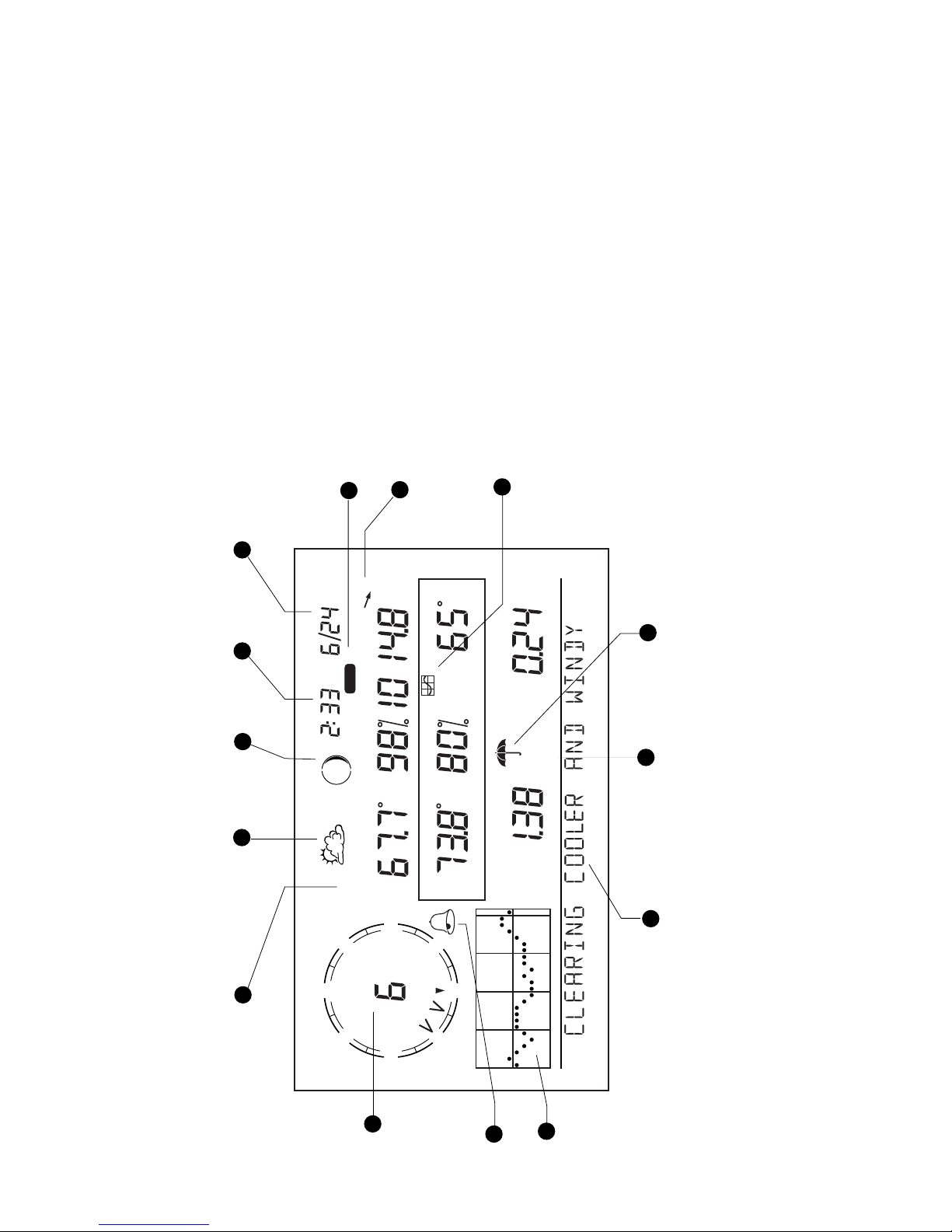
Display Features
1. Compass Rose
2. Graph and Hi / Low mode settings
3. Forecast Icons
4. Moon Phase Indicator
5. Time / Sunrise Time
6. Date / Sunset Time
7. 2nd button indicator
8. Barometric Trend Arrow
9. Graph Icon
10.Current Rain Icon
11. Station Number Indicator
12. Weather Ticker
13. Graph Field
14. Alarm icon
Page 3

Vantage Pro Manual Page 3
W
ELCOME
TO
V
ANTAGE
P
RO
. . . . . . . . . . . . . . . . . 7
Station Versions . . . . . . . . . . . . . . . . . . . . . . . . . . . . . . . . . . . . 7
Keyboard & Display . . . . . . . . . . . . . . . . . . . . . . . . . . . . . . . . . 7
Console Modes . . . . . . . . . . . . . . . . . . . . . . . . . . . . . . . . . . . . 8
Multiple Stations / Sensors . . . . . . . . . . . . . . . . . . . . . . . . . . . . 8
O
PTIONAL
S
ENSORS
. . . . . . . . . . . . . . . . . . . . . . . . . . . 8
O
PTIONAL
A
CCESSORIES
. . . . . . . . . . . . . . . . . . . . . . . . 9
C
ONSOLE
I
NSTALLATION
. . . . . . . . . . . . . . . . . . . . 11
Powering your Vantage Pro . . . . . . . . . . . . . . . . . . . . . . . . . . . 11
Changing batteries . . . . . . . . . . . . . . . . . . . . . . . . . . . . . . . . . . 12
Connecting the Cabled Console to the
Integrated Sensor Suite (ISS) . . . . . . . . . . . . . . . . . . . . . . . 13
Establishing reception between the Wireless Vantage Pro console
and the Integrated Sensor Suite (ISS) . . . . . . . . . . . . . . . . 13
D
ISPLAYING
THE
C
ONSOLE
. . . . . . . . . . . . . . . . . . . . . .14
Table & Shelf Display . . . . . . . . . . . . . . . . . . . . . . . . . . . . . . . . 14
Wall Display . . . . . . . . . . . . . . . . . . . . . . . . . . . . . . . . . . . . . . . 15
U
SING
THE
C
ONSOLE
. . . . . . . . . . . . . . . . . . . . . . . 19
S
ETUP
M
ODE
. . . . . . . . . . . . . . . . . . . . . . . . . . . . . . . .19
Entering & Exiting Setup Mode . . . . . . . . . . . . . . . . . . . . . . . . 19
Setup Mode Screens . . . . . . . . . . . . . . . . . . . . . . . . . . . . . . . . 19
Screen 1: ActiveTransmitters . . . . . . . . . . . . . . . . . . . . . . . . 20
Screen 2: Selecting transmitters . . . . . . . . . . . . . . . . . . . . . 20
Screen 3: Retransmit . . . . . . . . . . . . . . . . . . . . . . . . . . . . . . 22
Screen 4: Time & Date . . . . . . . . . . . . . . . . . . . . . . . . . . . . . 22
Screen 5: Latitude . . . . . . . . . . . . . . . . . . . . . . . . . . . . . . . . 23
Screen 6: Longitude . . . . . . . . . . . . . . . . . . . . . . . . . . . . . . . 23
Screen 7: Time Zone . . . . . . . . . . . . . . . . . . . . . . . . . . . . . . 23
Screen 8: Daylight Savings Settings . . . . . . . . . . . . . . . . . . 24
Screen 9: Daylight Savings Status . . . . . . . . . . . . . . . . . . . . 24
Screen 10: Elevation . . . . . . . . . . . . . . . . . . . . . . . . . . . . . . 25
Screen 11: Wind Cup Size . . . . . . . . . . . . . . . . . . . . . . . . . . 25
Screen 12: Rain Collector . . . . . . . . . . . . . . . . . . . . . . . . . . 25
Screen 13: Rain Season . . . . . . . . . . . . . . . . . . . . . . . . . . . 26
Exiting Setup Mode . . . . . . . . . . . . . . . . . . . . . . . . . . . . . . . . . 26
Page 4

Page 4 Vantage Pro Console Manual
C
URRENT
W
EATHER
M
ODE
. . . . . . . . . . . . . . . . . . . . . 27
Activating Weather Variables . . . . . . . . . . . . . . . . . . . . . . . . . . 27
Wind Speed and Direction . . . . . . . . . . . . . . . . . . . . . . . . . . 27
Temperature . . . . . . . . . . . . . . . . . . . . . . . . . . . . . . . . . . . . 28
Wind Chill . . . . . . . . . . . . . . . . . . . . . . . . . . . . . . . . . . . . . . . 28
Dew Point . . . . . . . . . . . . . . . . . . . . . . . . . . . . . . . . . . . . . . 28
Barometric Pressure . . . . . . . . . . . . . . . . . . . . . . . . . . . . . . 29
UV (Ultraviolet Radiation) . . . . . . . . . . . . . . . . . . . . . . . . . . 29
Heat Indices . . . . . . . . . . . . . . . . . . . . . . . . . . . . . . . . . . . . . 29
Rain Year, Rain Month, and Rain Rate . . . . . . . . . . . . . . . . 30
Daily Rain and Rain Storm . . . . . . . . . . . . . . . . . . . . . . . . . 31
Solar Radiation . . . . . . . . . . . . . . . . . . . . . . . . . . . . . . . . . . 31
ET (Evapotranspiration) . . . . . . . . . . . . . . . . . . . . . . . . . . . . 31
Selecting Units . . . . . . . . . . . . . . . . . . . . . . . . . . . . . . . . . . . . . 32
To change the units for any variable: . . . . . . . . . . . . . . . . . . 32
Calibrating, Setting, and Clearing Variables . . . . . . . . . . . . . . . 33
Calibration . . . . . . . . . . . . . . . . . . . . . . . . . . . . . . . . . . . . . . 33
Setting Variables . . . . . . . . . . . . . . . . . . . . . . . . . . . . . . . . . 34
Clearing variables . . . . . . . . . . . . . . . . . . . . . . . . . . . . . . . . 34
H
IGHS
AND
L
OWS
M
ODE
. . . . . . . . . . . . . . . . . . . . . . . 36
Accessing Highs and Lows . . . . . . . . . . . . . . . . . . . . . . . . . . . . 36
Exit Highs and Lows screen . . . . . . . . . . . . . . . . . . . . . . . . . . . 37
A
LARMS
M
ODE
. . . . . . . . . . . . . . . . . . . . . . . . . . . . . . 38
Three special alarms . . . . . . . . . . . . . . . . . . . . . . . . . . . . . . . . 38
Setting Alarms . . . . . . . . . . . . . . . . . . . . . . . . . . . . . . . . . . . . . 39
Setting the Time Alarm . . . . . . . . . . . . . . . . . . . . . . . . . . . . . . 39
Clearing Alarms . . . . . . . . . . . . . . . . . . . . . . . . . . . . . . . . . . . . 39
Silencing Alarms . . . . . . . . . . . . . . . . . . . . . . . . . . . . . . . . . . . . 39
G
RAPH
M
ODE
. . . . . . . . . . . . . . . . . . . . . . . . . . . . . . . 42
Entering and Exiting Graph Mode . . . . . . . . . . . . . . . . . . . . . . 42
Using and Understanding the Graph Mode’s Features . . . . . . 42
T
ROUBLESHOOTING
, R
EPAIR
, & W
ARRANTY
. . . . . .45
T
ROUBLESHOOTING
G
UIDE
. . . . . . . . . . . . . . . . . . . . . 45
O
NE
Y
EAR
L
IMITED
W
ARRANTY
. . . . . . . . . . . . . . . . . . 45
Q
UESTIONS
? C
ONTACT
THE
D
AVIS
S
ERVICE
C
ENTER
. 45
Page 5

Vantage Pro Manual Page 5
R
ADIO
T
RANSMISSION
D
IAGNOSTIC
S
CREEN
. . . . . . . .50
Receiver Gain Status . . . . . . . . . . . . . . . . . . . . . . . . . . . . . . . . 50
A
PPENDIX
: W
EATHER DATA . . . . . . . . . . . . . . . . . . 51
S
PECIFICATIONS . . . . . . . . . . . . . . . . . . . . . . . . . . . 59
Page 6

Page 6 Vantage Pro Console Manual
Page 7
Vantage Pro Manual Page 7
N
S
WE
NE
SE
NW
SW
C
HILL
W
IND
R
AIN R
ATE
in/hr
TEMP O
UT
HUM
IN
HU
M
O
UT
DAILY
RAIN
in
TEM
P IN
inm
b
BARO
M
ETER
STATIO
N
NO.1
F
F
pm
F
M
PH
L
ast 24 h
rs
h
r
E
ve
ry 1
N
W
S
E
N
W
ELCOME
TO
V
ANTAGE
P
RO
Welcome to Davis Instruments’ Vantage Pro Console. The Console, part of the
comprehensive Vantage Pro system, displays a wealth of weather information
and a forecast based on the latest meteorological algorithms. The console is
also a powerful weather computer, collecting, storing, and displaying historical weather data.
Station Versions
The Vantage Pro System is available in two models: Cabled and Wireless.
• Cabled Vantage Pro System
The Cabled Vantage Pro system links the Integrated Sensor Suite (ISS) to
the console using standard four-conductor cable.
•Wireless Vantage Pro
The wireless Vantage Pro console receives data transmitted by radio
from the solar-powered ISS. Neither the ISS, nor the console r equir es AC
power.
Keyboard & Display
The keyboard lets you view current and historical data, set and clear alarms,
change station modes, enter calibration numbers, set up and view graphs,
select sensors, and read the forecast. To learn more about the keyboard, see
“Activating Weather Variables” on page 27.
Page 8

Welcome to Vantage Pro
Page 8 Vantage Pro Console Manual
Console Modes
The Vantage Pro console operates in five different modes:
• Setup
Use Setup mode to enter the time, date, calibration numbers, and other
information required to process and display weather data.
• Current Data
Use this mode to read the current weather information.
• High / Low
Access the Highs and Lows mode with the High/Low key.
• Alarm
Set, clear, and review alarm settings in Alarm mode.
• Graph
Explore the console’s advanced graphing capabilities in Graph mode.
Multiple Stations / Sensors
The Wireless Vantage Pro system can receive transmissions from up to eight
different transmitters. See “Optional Sensors” below.
O
PTIONAL
S
ENSORS
The Vantage Pro system is extremely flexible. The following optional sensors
are available from your dealer or may be ordered directly from Davis Instruments. Please be aware that some options work with wireless units only.
• Solar Radiation Sensor (# 6450)
Measures solar radiation. Also required for calculating evapotranspiration (see “EvapoTranspiration (ET)” on page 57). Available for cabled
and wireless stations. Requires Sensor Mounting Shelf (#6672). See
“Optional Accessories” on page 9.
• Ultraviolet (UV) Radiation Sensor (#6490)
Measures UV radiation. Required for calculating the UV dose. A vailable
for Cabled and Wireless stations. Requires Sensor Mounting Shelf
(#6672). See “Optional Accessories” on page 9.
•
Wireless Integrated Sensor Suite (#6320)
A complete sensor package including rain, temperature, humidity, wind
speed and direction, with options for solar radiation and UV sensors.
• Wireless Temperature Station (#6370)
Measures and transmits air temperature from a remote location to the
console.
•Wireless Temperature / Humidity Station (#6380)
Measures and transmits air temperature and humidity from a remote
location to the console.
Page 9

Optional Accessories
Vantage Pro Console Manual Page 9
• Anemometer Transmitter Kit (#6330)
Allows separation of anemometer from ISS to capture wind speed and
direction from a remote location.
•Wireless Soil Moisture / Temperature Station (#6361)
Measures and transmits soil moisture and temperature data from up to
four soil moisture sensors and four temperature probes.
•Wireless Leaf Wetness / Temperature Station (#6341)
Measures and transmits leaf wetness and temperature data from up to
four leaf wetness sensors and four temperature probes.
Note: The Wireless Vantage Pro console can receive from up to eight total transmitters. Please see the
see “Maximum Transmitters per wireless Console/Receiver” on page 20 for description.
O
PTIONAL
A
CCESSORIES
The following accessories are available from your dealer or may be ordered
directly from Davis Instruments.
•WeatherLink
®
for Vantage Pro™ Data Logger & Software (#6510C)
Logs data gathered by the Vantage Pro, downloads it to your PC, and
generates reports and graphical displays. Storage interval (1, 5, 10, 15,
30, 60, or 120 minutes) is set by the user. The data logger will store
approximately 2, 9, 18, 27, 53, 107, or 213 days worth of data depending
on the selected storage interval. Windows
™
-compatible software lets you
analyze, plot, print, sort, and summarize the data.
WeatherLink
®
for Vantage Pro™ includes data logger, eight foot cable ,
software, and manual. Requires PC running Windows 95, 98, 2000, ME,
or NT and one free serial port.
• Sensor Mounting Shelf (#6672)
Required for mounting the optional Solar Radiation and/or UVsensors.
The mounting shelf attaches to the ISS.
• Cigarette Lighter Power Adapter (#6604)
Allows the Vantage Pro to draw power from a standard car cigarette
lighter.
•Telephone Modem Adapter (#6533)
Allows a dialup connection between the station and the computer.
• Extension Cables (#7876)
From Cabled Vantage Pro ISS to console. Maximum cable length is 1000’
feet (300 m).
#7876-040 Cable, 40’ (12 m) $18
#7876-100 Cable, 100’ (30 m) $40
#7876-200 Cable, 200’ (61 m) $70
Page 10

Welcome to Vantage Pro
Page 10 Vantage Pro Console Manual
Page 11
Vantage Pro Manual Page 11
N
S
WE
NE
SE
NW
SW
CHILL
WIND
RAIN RATE
in
/hr
TEMP OUT
HUM IN
HUM OUT
DAILY RAIN
in
TEMP IN
in
m
b
BAROMETER
STATION NO.1
F
F
p
m
F
M
P
H
L
a
s
t 2
4
h
rs
h
r
E
v
e
ry
1
N
W
S
E
N
The Vantage Pro console is designed to give extremely accurate readings. As
with any precision instrument, use care in its assembly and handling.
Although installing the console is relatively simple, following the steps outlined in this chapter and assembling the Vantage Pro correctly from the start
will ensure that you enjoy all of its features with a minimum of time and effort.
• WARNING: The Vantage Pro system uses power differenly from the way older Davis stations did. Use only
a Davis Vantage Pro AC power adapter. Using an older Davis adapter will damage your Vantage Pro!
Powering your Vantage Pro
• Cabled Console
Because the cabled Vantage Pro console supplies power to the ISS
through the connecting cable, you must use the AC power adapter or the
optional Car/Boat/RV Lighter Cor d to supply primary power. The three
C-cell batteries provide backup power during outages. They will operate
the station for four to six weeks.
•Wireless Console
The wireless Vantage Pro console does not require the use of the AC
adapter, although you may use the included adapter if you wish. The
three C-cell batteries should power your wireless console/receiver for
approximately one year. We do not recommend using rechargeable
NiCad batteries, because they will not last as long.
C
ONSOLE
I
NSTALLATION
Page 12
Console Installation
Page 12 Vantage Pro Manual
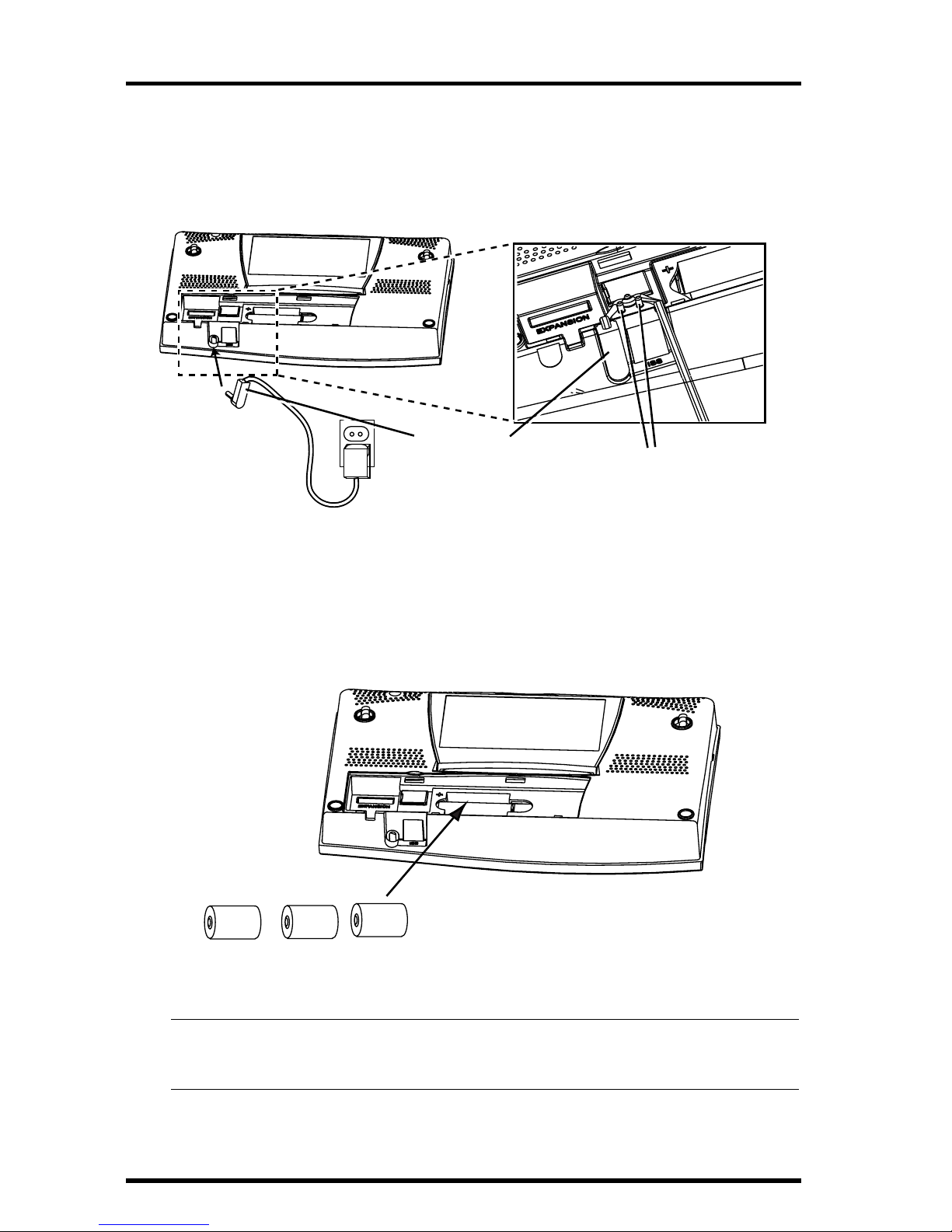
1. Insert the power adapter plug into the jack located on the bottom of the console, then
plug the other end of the adapter into an appropriate power outlet.
The Vantage Pro should run through a brief self-test procedure. All the display segments on the LCD appear and the console will beep twice.
2. Insert the batteries.
Remove the battery cover located on the back of the console by pressing the
two latches at the top of the cover. Insert three C batteries into the battery
channel, negative (or flat) terminal first.
Note: To remove batteries, place the Vantage Pro Console face down on a flat, firm surface. Insert a finger-
tip between the two exposed batteries. Press the middle battery down toward the notch (toward the
“hidden” battery. This will relieve the tension on the first battery and allow you to withdraw it.
Power Plug
Wrap Cord Around Pins
Powering the Console
Battery
Battery
Battery
Inserting the Batteries
Page 13
Vantage Pro Manual Page 13
3. Replace the battery cover.
After power-up the Vantage Pro will automatically enter Setup mode. Setup
mode will lead you through setting up and calibrating your station. See “Setup
Mode” on page 19.
Changing batteries
To ensure you preserve any data you’ve accumulated in the station memory , do
two things before you change the batteries: 1) Plug in the AC adapter and 2)
Enter Setup Mode by pressing the DONE and “-” keys first. This makes sure
the station isn’t writing any data to memory.
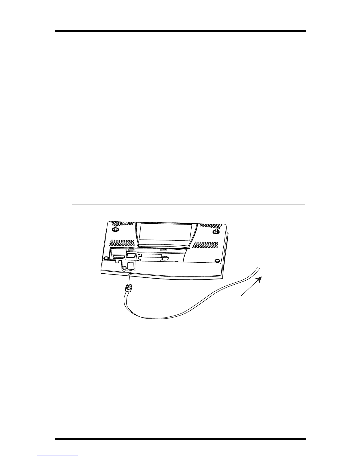
Connecting the Cabled Console to the
Integrated Sensor Suite (ISS)
The Vantage Pro comes with 100 feet (30m) of cable. Maximum cable length
from ISS to console is 1000 feet. See “Optional Accessories” on page 9 to purchase additional cable.
1. Gently insert the console end of the 4-conductor wire into the console receptacle
marked “ISS” until it clicks into place.
• WARNING: Do not force the connector into the receptacle.
2. Ensure that the ISS cable is not twisted through the access hole.
3. Test the connections between the ISS and the console.
Spin the wind cups and change the direction of the vane. If the ISS is powered and the connection between the ISS and the console is correct, you
should see the wind direction and speed fields changing. T ip the rain bucket
back and forth. You should see rain registering. Check the other fields to
ensure you’re receiving from them, too.
To ISS
Page 14
Console Installation
Page 14 Vantage Pro Manual
Establishing reception between the Wireless Vantage Pro console and the
Integrated Sensor Suite (ISS)
As you position your console, be aware of possible interference from cordless
phones and other items. To prevent interference, maintain a distance of 10 feet
between the Vantage Pro console and the cordless phone (handset and base).
Also, for best reception, avoid positioning the console near large metallic surfaces (e.g., most refrigerator surfaces).
Please test communications between the Console/Receiver and the ISS (or
other transmitter) BEFORE permanently mounting your ISS. Remember that
the ISS transmits packets every few seconds. Therefore, there may be a 2 to 3
second delay before the console display updates. For more information about
locating the sensor transmitter and testing reception, consult the ISS or other
transmitter manual.
D
ISPLAYING
THE
C
ONSOLE
You should place the console in a location where the keyboard is easily accessible and the display is easy to read. For more accurate readings, follow these
suggestions:
•Avoid placing the console in direct sunlight. This may cause erroneous readings
and / or damage to the unit.
•Avoid placing the console near radiant heaters or heating / air conditioning ducts.
• If you are mounting the console on a wall, choose an inner or interior wall. Avoid
walls that heat up or cool down depending on the weather.
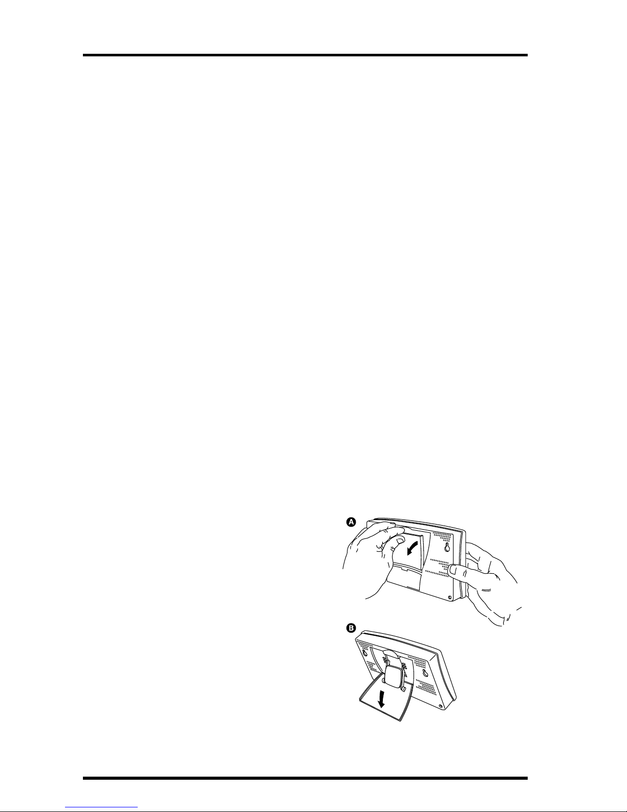
Table & Shelf Display
The kickstand may be set at five different angles appropriate for different display angles.
1. Lean the kickstand out by pulling on its
top edge.
You’ll see the indentation for your
finger at the top edge of the console.
2. Slide the catch to arrest the kickstand in
the appropriate angle.
Choose low angles for display on a
coffee table or other low area.
Choose higher angles for display on
a desk or shelf.
3. Pull up on the stand to close it. It will be
a little tight, so it’s okay to push hard
enough to get it to slide.
Opening the Stand for Table or
Shelf Display
Page 15
Displaying the Console
Vantage Pro Manual Page 15
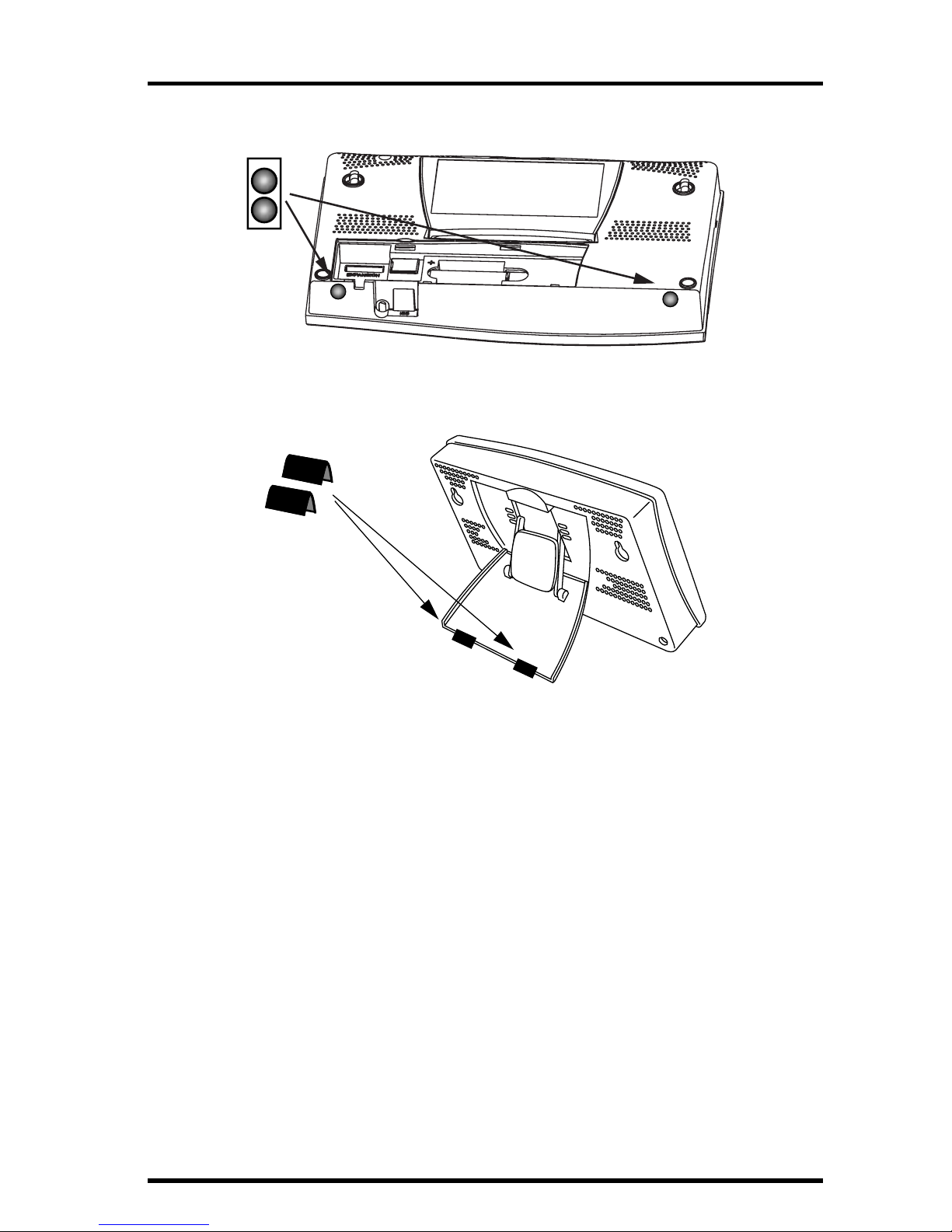
4. Install the two round rubber feet on the bottom of the console.
5. Install the two rubber channel feet on the kickstand.
Installing Round Rubber Feet
Installing Rubber Channel Feet
Page 16
Console Installation
Page 16 Vantage Pro Manual
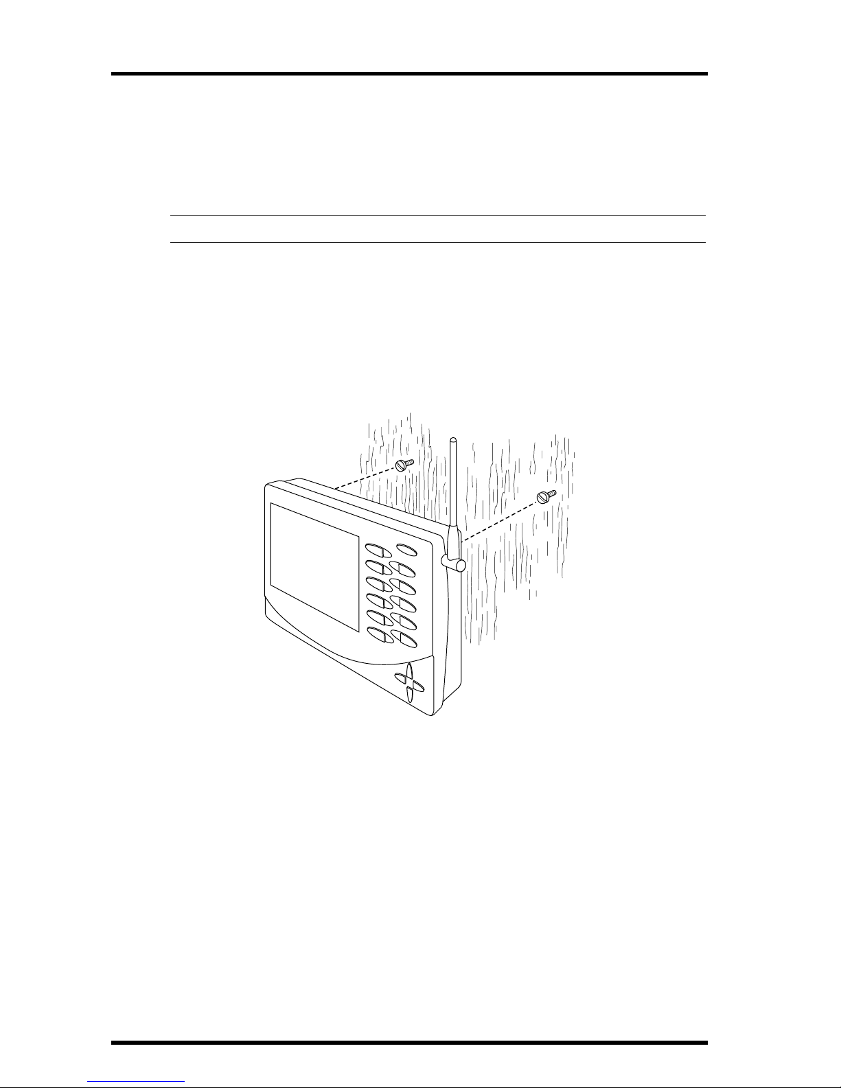
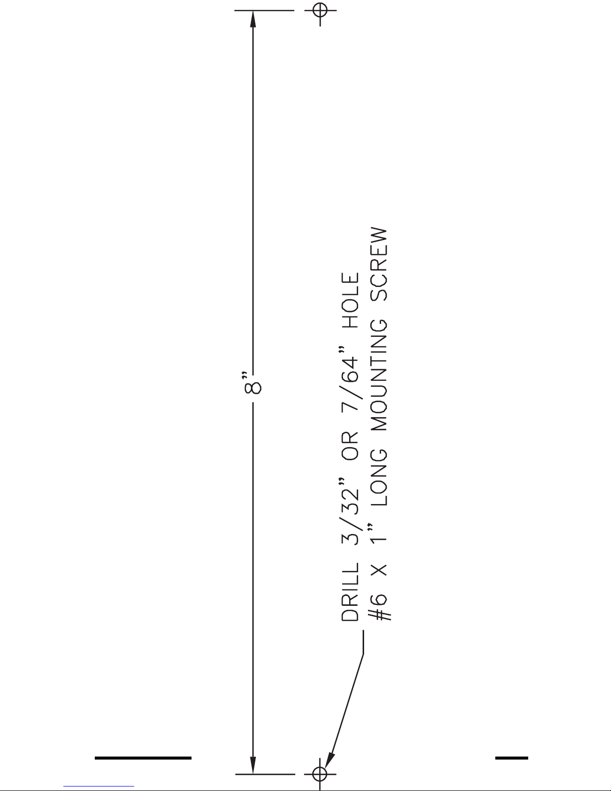
Wall Display
1. Hold the template provided on page 17 flat against the wall and use a pencil to mark
the location of the two keyholes.
If you are installing a standard Vantage Pro console with sensor cable running inside the wall, attach the console over an empty switch box.
Note: Alternatively, you can use a ruler to mark two holes 8 inches (203 mm) apart.
2. Use an electric drill with a 3/32 or 7/64” (2.5 mm) drill bit to make pilot holes in these
locations.
3. Using a screwdriver, drive the two #6 x 1” pan head self-threading screws into the
wall. Leave at least 1/8” (3 mm) between the wall the the heads of the screws.
4. Retract the kickstand into its upright and locked position.
5. Slide the keyholes on the back of the console over the two screw heads.
Wall Mounting the Console
Page 17
Displaying the Console
Vantage Pro Manual Page 17
Use this template to
hang the console on
a wall
Page 18

Console Installation
Page 18 Vantage Pro Manual
Page 19

N
S
WE
N
E
S
E
N
W
S
W
CHILL
WIND
RAIN RATE
in/hr
TEMP OUT
HUM IN
HUM OUT
DAILY RAIN
in
TEMP IN
inmb
BAROMETER
STATION NO.1
F
F
pm
F
MPH
Last 24 hrs
hr
Every 1
N
W
S
E
N
Vantage Pro Manual Page 19
U
SING
THE
C
ONSOLE
The Vantage Pro display and keyboard are designed for easy access to the most
important weather information. The large LCD display is your window on current and past environmental conditions, as well as the place to find the forecast.
The keyboard lets you interact with the station computer, view current and historical weather information, set and clear alarms, change station modes, enter
calibration numbers, set up and view graphs, select sensors, read the forecast,
and so on.
The console operates in five different modes: Setup, Current Weather, Highs
and Lows, Alarm, and Graph.
S
ETUP
M
ODE
Setup Mode lets you choose settings that determine how your Vantage Pro station operates.
Entering & Exiting Setup Mode
The console will automatically enter Setup Mode when you first power up.
Later, if you need to make any changes, access the Setup Mode by pressing the
DONE and “-” keys at the same time. Exit Setup by pressing and holding the
DONE key until the Current Weather screen appears.
Setup Mode Screens
On entering the Setup Mode, a sequence of screens will appear on the console.
Pressing DONE will take you to the next screen in the sequence. Pressing BAR
takes you to the previous screen.
Page 20
Using the Console
Page 20 Vantage Pro Console Manual
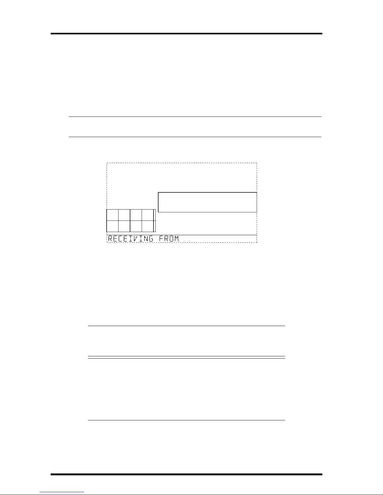
Screen 1: ActiveTransmitters
Screen 1 displays the active transmitters located in your area. The ticker will
display the message “Receiving from...” and the active transmitter IDs will be
illuminated. In addition, an “X” should intermittently appear in the lower
right-hand corner o f the screen. The rest of the display screen will be blank. If
you have a cabled station, this screen will display “Receiving from station No.
1.”
Note: Transmitters must be switched on for the console to recognize them. Refer to your ISS or other trans-
mitter manual to see how to switch them on.
This screen requires no input; it simply shows you what transmitters the console can receive. Press and release the “DONE” key to move to screen 2.
Each wireless console/receiver may receive signals from up to eight different
transmitters ; however, only certain combinations of transmitters are possible.
Table 1 below lists the maximum numbers of transmitter types each console/
receiver can handle:
Screen 2: Selecting transmitters
Use setup screen 2 to tell the console/receiver which transmitter IDs to listen
to, and what kind of station each transmitter represents.
Table 1: Maximum Transmitters per wireless Console/Receiver
Transmitter Type
Maximum per
Console (8
total)
Integrated Sensor Suite (ISS) 1
Anemometer T r ansmitter Kit 1
Leaf Wetness/Temperature Station 1
Soil Moisture/Temperature Station 1
Temperature Station 8
Temperature/Humidity Station 8
STATION NO.1 4
Setup Screen 1: Transmitters. This screen shows the Console receiving transmssions from transmitter IDs 1 and 4.
Page 21

Setup Mode
Vantage Pro Console Manual Page 21
• Cabled station owners, simply press “DONE” and proceed to setup screen 3.
•Wireless station owners
You probably do NOT need to change transmitter IDs. The console will
automatically find the factory default signal from the ISS. This should complete setup screen 2 for most owners. Every data packet the station receives
toggles an“X” in the bottom right corner of the screen.If your console picks
up the ISS’s transmissions, press “DONE” and move on to screen 3.
Sometimes, however, you may need to change the station ID. This might
happen if a neighbor is using another Davis transmitter or if you have purchased an optional sensor.
◆ To activate reception on different ID codes, press the left or right arrow key to
scroll between transmitter IDs.
Note: Station IDs do not have to be in order. The factory default transmitter ID for the ISS is “1”.
See your transmitter’s manual to learn how to set the transmitter ID.
◆ Once you’ve settled on the ID you wish to use, use the "+" or "-" keys to acti-
vate reception of that ID code.
As each different ID lights on the screen, the ticker will display the
word “ON” or “OFF”. “ON” means the console/receiver will listen to
that transmitter’s signal. “OFF” means the console/receiver will
ignore signals from that transmitter.
◆ Now, press the “GRAPH” key to change the type of station assigned to each
transmitter number.
When a station is listed as “ON”, one of the possible station types (ISS,
TEMP, HUM,TEMP HUM, WIND, LEAF, SOIL, or SENSORLINK) will
be displayed in the ticker. Scroll through this list until the correct station type appears.
Note: If you’re using a Temperature/Humidity station and no ISS, select Temp/Hum as described above,
then press the HIGH/LOW key. If you’re using an ISS as a Temperature/Humidity station, select ISS,
then presss the HIGH/LOW key. In both cases you’ll see a .25X in the lower right of the screen.
Press and release the “DONE” key to move to screen 3.
1
Setup Screen 2: Here’s what should greet most new Vantage Pro owners. The console
comes factory pre-set at transmitter ID 1. “ON” means the console will receive signals
from that ID and will assume the transmitter is an ISS. For most owners, this will complete
this step. See the ISS manual for further details.
Page 22

Using the Console
Page 22 Vantage Pro Console Manual
Screen 3: Retransmit
The console/receiver can re-transmit data to other console/receivers, or to the
Davis Weather Echo and Weather Echo Plus.
Note: This feature is not available in the cabled Vantage Pro station.
Setup screen 3 lets you switch the retransmit feature on or of f. Use the "+" or "-"
arrow key to choose “Retransmit On” or “Retransmit Off”. Use the STATION
key to choose and assign a transmission ID to the console/receiver. Note that
only IDs you’re not already using will appear.
Press and release the DONE key to move to screen 4.
Screen 4: Time & Date
On first power-up, the time and date are set to the factory default January 1,
2000, 12:00 midnight.
• Enter Time
Press and release 2ND, then UNITS if you wish to change from the 12- to
the 24-hour clock, then use the “+” or “-” key to change the hour. Press the
RIGHT arrow key to move to the minutes field, then use “+” or “-” key to
change the minutes.
• Enter Date
Press and release 2ND, then UNITS if you wish to change from MM/DD to
DD.MM or vice versa. Use “+” or “-” to change the first field. Continue
pressing the RIGHT arrow key to move to the next field, and use “+” or “-”
to change the number shown in that field. Press the LEFT arrow key to go
back to the previous field.
When you’re done, press and release the DONE key to move to screen 5.
2
am
Page 23

Setup Mode
Vantage Pro Console Manual Page 23
Screen 5: Latitude
To give you the best forecast, as well as calculate the correct times for sunset
and sunrise for your location, Setup will ask you to enter your latitude and longitude.
Note: Latitude and longitude are a way of identifying your position on the earth. Latitude measures dis-
tance north or south of the equator . L ongitude measures distance east or west of the P rime Meridian,
an imaginery line running north and south through Greenwich, England.
If you do not know your latitude and longitude, there are several ways to find
out. Many atlases and maps include latitude and longitude lines. You can also
talk to the reference department of your local library, or try calling your local
airport. The more accurate you are, the better; however, a reasonable estimate
will work, too.
Use the LEFT and RIGHT arrow keys to move between fields. Use the "+" and
"-" arrow keys to change digits. Press 2ND, then UNITS to specify North or
South (of the equator). Press and release the DONE key to move to screen 6.
Screen 6: Longitude
Enter your longitude as above. Press 2ND, then UNITS to specify EAST or
WEST (of the Prime Meridian). Press and release the DONE key to move to
screen 7.
Screen 7: Time Zone
The console is pre-programmed with a combination of US timezones and the
names of major cities representing time zones around the world. Use the "+"
and "-" keys to view the choices. If your time zone is not shown, press the 2ND
key to enter your UTC offset.
Page 24

Using the Console
Page 24 Vantage Pro Console Manual
Note: UTC (Universal Time Coordinate) offset measures the difference between the time in any timezone
and a standard time, set by convention as the time at the Royal Observatory in Greenwich, England.
For example, Hayward, California, the home of Davis Instruments, observes Pacific Standard Time.
The UTC offset for Pacific Standard Time is -8:00, or eight hours behind Universal Time. When it’s
7:00 pm (1900 hours) UT, it’s 19 - 8 = 1100 hours, or 11:00 am in Hayward.
Press and release the DONE key to move to Setup screen 8.
Screen 8: Daylight Savings Settings
Use the "+" and "-" keys to choose Auto or Manual. Most users in North America, including Mexico (excepting Saskatchewan, Eastern Indiana, Arizona, and
Hawaii), as well as users in Australia (excepting Western Australia, Northern
Territory, and Queensland) and Europe may choose the AUTO setting. The
console is pre-programmed with appropriate starting and stopping dates for
Daylight Savings Time for the r egions listed above, as long as you have enter ed
your correct time zone in screen 7. Users not living in the areas listed above
should choose MANUAL.
Press and release the DONE key to move to screen 9.
Screen 9: Daylight Savings Status
If you chose MANUAL in screen 8, use the "+" and "-" arrow keys to turn Daylight Savings Time on or off on the appropriate days of the year. If you chose
AUTO in screen 8, the console will display the appropriate setting, based on
the current time and date. Press and release the DONE key to move to screen
10.
Page 25

Setup Mode
Vantage Pro Console Manual Page 25
Screen 10: Elevation
Meteorologists standardize barometric pr essure data to sea level so that surface
readings are comparable, whether they’re taken on a mountainside or by the
ocean. To make this same standardization and ensure accurate readings, enter
your elevation in this screen.
If you do not know your elevation, there are several ways to find out. Many
atlases and almanacs include elevation for cities and towns. You can also talk to
the reference department of your local library.
Use the LEFT and RIGHT arrow keys to move between fields. Use the "+" and
"-" keys to select digits. Use the UNITS key to select feet or meters. Press and
release the DONE key to move to Setup screen 11.
If you are below sea level, such as some places in California like Death Valley,
first enter the elevation as a postive number. Then, select the “0” immediately
to the left of the leftmost non-zero digit and press the “-” and “+” keys to select
“-”. In the example above you would select the “0” to the left of the “2”, and
then you would be able to display a “-”.
Note: You can only select a negative symbol after you have entered a non-zero digit, and only in the posi-
tion immediately to the left of a non-zero digit.
The more accurate you are, the better; however, a reasonable estimate will
work, too.
Screen 11: Wind Cup Size
All Vantage Pro Stations come with large wind cups. Switch this setting to
small only if you have separately purchased and installed small wind cups.
Use the "+" and "-" arrow keys to switch between large and small. Press and
release the DONE key to move to screen 12.
Note: Large wind cups are more sensitive to low wind speeds and are the best choice for most users. Small
wind cups are less sensitive at low wind speeds; however, they are more resilient at higher speeds.
Install small wind cups only if you regularly expect winds over 120 mph (194 kph).
Page 26

Using the Console
Page 26 Vantage Pro Console Manual
Screen 12: Rain Collector
Your Vantage Pro is pre-configured for the rain collector. Simply press the
DONE key to move to the next screen. You may change the rain display’s units
from inches to millimeters by pressing 2ND, then the UNITS key.
Screen 13: Rain Season
Because rainy seasons begin and end at different times in dif ferent parts of the
world, you must specify the month you wish your yearly rain data to begin.
January is the default. Use the "+" and "-" arrows to select the appropriate
month.
Exiting Setup Mode
Press and hold down the DONE key to exit setup mode. The screen will return
to the current conditions screen. Re-enter setup mode at any time by pressing
and holding the DONE key, then pressing the "-" key.
Page 27

Current Weather Mode
Vantage Pro Console Manual Page 27
C
URRENT
W
EATHER
M
ODE
The current weather screen is the heart of the display and where you’ll likely
spend most of your time. Up to ten weather variables are displayed simultaneously on the Vantage Pro’s LCD screen. The following variables are always
displayed: barometric pressure, outside temperature, outside humidity, and
wind direction. You can choose the other variables you’d like displayed on the
the screen.
Activating Weather Variables
Displaying any current weather information is straightforward. Press any
function key to display that weather variable’s current value. Selecting a variable also activates that variable’s graph.
You can also select any variable currently displayed on the LCD screen using
the “+”, “-” and LEFT and RIGHT arrow keys. Pushing these keys will move
the graph icon to the next data field in the selected direction.
You can find more detailed descriptions of weather variables and their measurements in “Appendix: Weather Data” starting on page 51.
Wind Speed and Direction
•Wind Speed
Press the WIND key to select the wind speed field.
Wind speed may be displayed in miles per hour
(mph), kilometers per hour (kph), meters per second
(m/s), and knots (knots). Press 2ND and UNITS to
change the units.
•Wind Direction
The solid arrow within the compass rose shows the current wind direction. The arrow caps display the last six
10-minute dominant wind directions. The console measures the dominant wind direction every ten minutes,
discarding the oldest measurement and entering the new
measurement at the top of the list. If the dominant wind
direction does not vary over a 60 minute period, only one arrow cap will be
displayed.
To show wind direction in numerical form, WIND key again. The wind
direction is displayed in degrees.
N
W
NE
SESW
Vertical Scale: X10
WIND
RAIN YEAR
in
TEMP OUT
HUM IN
HUM OUT
DAILY RAIN
in
TEMP IN
hPa
BAROMETER
STATION NO.1
F
F
F
MPH
Last 24 hrshrEvery 1
S
E
NW
pm
TEMP IN
F
TEMP OUT
F
HEAT INDEX
N
W
NE
SESW
WIND
MPH
E
S
NW
CHILL
WIND
Page 28

Using the Console
Page 28 Vantage Pro Console Manual
Temperature
• Outside Temperature
Press the TEMP key to select the outside temperature field.
Note that the graph icon appears next to the data field.
Temperature data may be displayed in either degrees
Fahrenheit (ºF) or Centigrade (ºC).
• Inside Temperature
Press the TEMP key again to show the inside temperature. Again, the
graph icon appears next to the data field.
• Humidity
Press the HUM key to select the outside humidity field.
Press the HUM key again to activate the inside humidity
field. Humidity is displayed in percent relative humidity.
Wind Chill
• Current Wind Chill
Press and release the 2ND key, then press the
CHILL key to select the Wind Chill field. Note
that the console calculates wind chill based on
the ten–minute average wind speed.
Wind Chill is displayed in either degrees Fahrenheit (ºF) or Centigrade
(ºC).
Dew Point
• Current Dew Point
Press and release the 2ND key, then press the
DEW PT key to select the Dew Point field.
Dew Point is displayed in either degrees
Farenheit (ºF) or Centigrade (ºC).
HEAT
TEMP
N
W
NE
SESW
Vertical Scale: X10
WIND
RAIN YEAR
in
TEMP OUT
HUM IN
HUM OUT
DAILY RAIN
in
TEMP IN
hPa
BAROMETER
STATION NO.1
F
F
F
MPH
Last 24 hrshrEvery 1
S
E
NW
pm
HEAT INDEX
HUM OUT
HUM IN
CHILL
F
DEW POINT
F
hPa
BAROMETER
Humidity, Pressure, Dew Point,
& Wind Chill
DEW PT
HUM
CHILL
WIND
2
ND
DEW PT
HUM
2
ND
Page 29

Current Weather Mode
Vantage Pro Console Manual Page 29
Barometric Pressure
• Current Barometric Pressure
Press the BAR key to select the barometric pressure.
Barometric pressure may be displayed in inches (in), milli-
meters (mm), millibars (mb) or hectoPascals (hPa).
•Pressure Trend Arrow
The Barometric Trend Arrow depicts the current barometric trend, measured over the last 3 hours. The trend arrow is always displayed (unless
less than three hours of pressure data is available), whether the barometric
pressure is selected or not.
UV (Ultraviolet Radiation)
• Current UV
Press the UV key to display the current UV Index.
Press again to see MEDS.
See “UV (Ultra Violet) Radiation” on page 55.
Heat Indices
• Heat Index
Press and release the 2ND key, then press the
HEAT key to display the Heat Index. See
“Apparent Temperature Measures” on page 51.
ET
BAR
N
W
NE
SESW
Vertical Scale: X10
WIND
RAIN YEAR
in
TEMP OUT HUM OUT
DAILY RAIN
in
TEMP IN
hPa
BAROMETER
STATION NO.1
F
F
THSW INDEX
F
MPH
Last 24 hrshrEvery 1
S
E
NW
pm
F
HEAT INDEX
UV
index
THSW INDEX
F
UV
index
SUN
UV
HEAT
TEMP
2
ND
Page 30

Using the Console
Page 30 Vantage Pro Console Manual
• THSW Index
If you have installed the optional Solar Radiation Sensor, repeat the
sequence one more time to display the THSW (Temperature–Humidity–
Sun–Wind Index).
Both heat indices appear in the same place on the screen and may be displayed, like temperature and wind chill, as either degrees Fahrenheit (ºF) or
Centigrade (ºC).
Rain Year, Rain Month, and Rain Rate
• Rain Rate
Press the RAIN
YR key to display the current rain rate.
Rain Rate may be displayed as either inches per hour (in/hr) or millimeters
per hour (mm/hr). Rain Rate will show zero, and the umbrella icon will not
appear, until 0.02 in (.508mm)of rain falls within a 15–minute period.
• Month-to-date precipitation
Press the RAIN
YR again to select the month-to-date precipitation record.
Monthly rain displays the precipitation accumulated since the calendar
month began. Month-to-date precipitation is displayed in inches (in) or
millimeters (mm).
•Year-to-date precipitation
Press the RAIN
YR key a third time to display the year-
to-date precipitation record. Yearly rain displays the
precipitation accumulated since the 1st of the month
you’ve chosen in Setup Mode (See “Screen 13: Rain
Season” on page 26.) Y ear-to-date pr ecipitation is displayed in inches (in) or
millimeters (mm).
Note: The“Y ear -to-date” and “Month-to-date” registers record precipitation accumulation for one year and
one month respectively; however, you may start each counting period whenever you wish.
N
W
NE
SESW
Vertical Scale: X10
WIND
RAIN YEAR
in
TEMP OUT
HUM IN
HUM OUT
DAILY RAIN
in
TEMP IN
hPa
BAROMETER
STATION NO.1
F
F
F
MPH
Last 24 hrshrEvery 1
S
E
NW
pm
HEAT INDEX
DAILY RAIN
in
RAIN RATE
in/hr
RAIN STORM
in
RAIN YEAR
in
RAIN MO
in
Daily Rain, Rain Storm, Rain Year, Rain Month, & Rain Rate
RAIN DAY
RAINYR
Page 31

Current Weather Mode
Vantage Pro Console Manual Page 31
Daily Rain and Rain Storm
• Daily Rain
Press and release the 2ND key, then press the
RAIN
DAY key. Daily Rain displays the rain
accumulated since 12 midnight. Any rain accumulated in the last 24 hours will be displayed
in the ticker.
• Rain Storm
Rain Storm displays the rain total of the last rain event. It takes two rain
clicks to begin a storm event and 24 hours without rain to end a storm
event.
Repeat the above sequence: press and release the 2ND key, then press the
RAIN
DAY key. Rain Storm will only increment after 0.02 in (.508mm) rain.
All rain accumulation may be displayed as either millimeters (mm) or
inches (in).
Solar Radiation
• Current Solar Radiation
Press and release the 2ND key, then press the
SUN key to display the current solar radiation
reading.
Solar radiation is displayed as Watts per
square meter (W/m
2
).
Note: To display solar radiation readings, you must have installed the optional Solar Radiation sensor. (See
“Optional Sensors” on page 8)
ET (Evapotranspiration)
• Current ET
Press and release the 2ND key, then press the ET
key to display the current evapotranspiration
reading.
RAIN DAY
RAINYR
2
ND
LAMPS
N
W
NE
SESW
GRAPH
Vertical Scale: X10
WIND
RAIN YEAR
in
TEMP OUT
HUM IN
YEAR
HUM OUT
DAILY RAIN
in
TEMP IN
hPa
BAROMETER
STATION NO.1
F
F
F
MPH
Last 24 hrshrEvery 1
S
E
NW
pm
HEAT INDEX
ET
mm
ET
MO
mm
ET
YEAR
mm
SUN
W/m
2
Current ET, ET Month, ET Year, & Solar Radiation
SUN
UV
2
ND
LAMPS
ET
BAR
2
ND
Page 32

Using the Console
Page 32 Vantage Pro Console Manual
• Monthly ET
Repeat the sequence (i.e. Press and release the 2ND key, then press the ET
key) to display Monthly ET.
•Yearly ET
Repeat the sequence a third time to display the ET reading since January 1st
of the current year.
Note: To display ET readings, you must install the optional Solar Radiation sensor.
Selecting Units
Most weather variables may be displayed in at least two different units, including US and Metric systems, although some variables feature more possibilities.
Barometric pressure, for example, may be displayed in millibars, millimeters,
inches, or hectoPascals. Note that you can set each variable’s units independently — some to US, some to Metric as you like.
You may change the units display at any time.
To change the units for any variable:
1. Activate the variable using the keypress sequences described above.
2. Press and release the 2ND key.
3. Press the UNITS key.
The selected variable’s units will change. Repeat steps 2 and 3 until the
desired units appear.
For example, to select Barometric pressure units, activate the Barometric
presure by pushing BAR. Next, press and release the 2ND key, then press the
UNITS key. The units field will display millibars, millimeters, inches, or hectoPascals. Repeating these steps cycles through all four selections. Stop when the
the desired unit appears.
BAROMETER
mb
BAROMETER
BAROMETER
mm
in
Barometric Pressure: millibars (mb), millimeters (mm) and inches (in)
Page 33

Current Weather Mode
Vantage Pro Console Manual Page 33
Calibrating, Setting, and Clearing Variables
Calibration
To fine-tune your station, you can calibrate most of the weather variables. For
example, if your outside temperature seems consistently too high or too low,
you can enter an offset to correct the deviation.
• Calibrating temperature and humidity
You can calibrate inside and outside temperature, inside and outside
humidity, as well as any extra temperature or humidity sensors you have
transmitting to Vantage Pro.
1. Select the variable you’d like to calibrate.
2. Press and hold the SET key.
After a moment, the variable you’ve selected will begin to blink. Keep
holding the SET key until a message appears in the ticker saying “calibration offset 0”.
3. Use the “+” and “-” keys to add or subtract from the variable’s value.
Inside and outside temperature are calibrated in 0.1 ˚F or 0.1 ˚C increments, up to a maximum offset of +12.7 (˚F or ˚C) and a minimum offset of -12.8 (˚F or ˚C). The variable will change value and the ticker will
show the offset you’ve entered.
4. Press DONE to exit calibration.
• Calibrating wind direction,
1. Press WIND twice so that the wind direction is displayed.
2. Press and hold the SET key.
The wind direction will begin to blink. Continue holding until “Cal 0”
appears in the ticker.
3. Use the “+” and “-” keys to add or subtract from the variable’s value. Use the
LEFT and RIGHT arrow keys to move between the hundreds, tens, and ones
places in the wind direction readout.
4. Press DONE to exit calibration.
The next time you enter wind direction calibration, the ticker will display the current offset.
• Calibrating barometric pressure
First, make sure that you’ve already entered the correct elevation in setup
mode.
1. Select the barometer by pressing BAR.
2. Press and hold SET.
The pressure variable will blink. Keep holding SET until the ticker
reads “set barometer...”.
3. Use the “+” and “-” keys to add or subtract from each digit’s value. Use the
LEFT and RIGHT arrow keys to move between the digits in the pressure readout.
4. Press DONE to exit calibration.
Page 34

Using the Console
Page 34 Vantage Pro Console Manual
Setting Variables
You can set values for the following variables:
• Daily rain
Change the daily rain total. The monthly and yearly rain totals are changed
according to the amount you enter here.
• Monthly rain
Set the current month’s total rain. The yearly rain total is not affected by
this change.
•Yearly rain
Set the current year’s rain total here.
• Daily ET
Set the daily ET total. The monthly and yearly ET totals are changed
according to the amount you enter here.
• Monthly ET
Set the current month’s ET here. Yearly total is not affected.
•Yearly ET
Set the current year’s total ET here.
1. Select the variable you’d like to set.
2. Press and hold the SET key.
The variable will blink. Keep holding until all digits are lit and only one
digit is blinking.
3. Use the “+” and “-” keys to add or subtract from each digit’s value. Use the LEFT and
RIGHT arrow keys to move between the digits in the variable.
4. Press DONE to exit.
Clearing variables
To clear any of the following variables
1. Select the variable you’d like to clear.
2. Press and hold the CLEAR key.
The variable you’ve chosen will blink. Keep holding the key until the value
changes to zero or, in the case of the barometer, the raw barometer value.
• Barometer
Clearing the barometer value clears (a) any pressure offset you’ve entered
using SET and (b) the elevation entry.
• Daily rain
Clearing the daily rain sets the daily rain total, the last 15 minutes of rain,
the last three hours of rain sent to the forecast algorithm, the umbrella icon,
and subtracts the old daily rain total from the monthly and yearly rain
totals.
If, while installing, you accidentally cause a click or two in the rain collector, you can correct the reading by clearing the daily rain total.
Page 35

Current Weather Mode
Vantage Pro Console Manual Page 35
• Monthly rain
Clears the monthly rain total. Does not affect yearly rain total
•Yearly rain
Clears the yearly rain total.
•Wind
Clears the wind direction calibration.
• Daily ET
Clears daily ET and subtracts the old daily ET total from the monthly and
yearly ET totals.
• Monthly ET
Clears the current monthly ET total. Does not affect †he yearly ET total.
•Yearly ET
Clears the current yearly ET total.
Page 36

Using the Console
Page 36 Vantage Pro Console Manual
HIGHS AND LOWS MODE
The Vantage Pro records highs and lows for many weather conditions over
three different periods: days, months, and years. Except for Yearly Rainfall, all
high and low registers are cleared automatically at the end of each period. For
example, daily highs are cleared at midnight, monthly highs are cleared at
month–end midnight, yearly highs are cleared at year–end midnight. You may
enter the month that you would like the Yearly Rainfall accumulation to clear.
The Yearly Rainfall will clear on the first day of the month you choose.
Table 2: Console Highs and Lows
Accessing Highs and Lows
•Press the HI/LOW button to enter the Highs and Lows mode.
The DAY and HIGHS icons light up and the station displays the highs for
all visible fields.
C
ONDITION HIGH LOW
DAY
TIME &
D
ATE
MONTH YEAR ADDITIONAL
INFORMATION
Outside Temperature Yes Yes Yes Yes Yes
Inside Temperature Yes Yes Yes Yes Yes
Outside Humidity Yes Yes Yes Yes Yes
Inside Humidity Yes Yes Yes Yes Yes
Heat Index Yes Yes Yes Yes
Temp / Hum / Wind / Sun Index Yes Yes Yes Yes requires solar radiation
sensor
Wind Chill Yes Yes Yes Yes
Wind Speed Yes Yes Yes Yes Direction of High
Rainfall Rate Yes Yes Yes Yes
Daily Rain Total Total Total
UV Index Yes Yes Yes Yes requires UV sensor
Solar Radiation Yes Yes Yes Yes requires solar radiation
sensor
Dew Point Yes Yes Yes Yes Yes
Evapotranspiration Total Total Total requires solar radiation
and leaf wetness sensors
Soil Moisture Yes Yes Yes Yes Yes requires soil moisture
sensor
Leaf Wetness Yes Yes Yes Yes Yes requires leaf wetness
sensor
Page 37

Highs and Lows Mode
Vantage Pro Console Manual Page 37
• Use the "+" and "-" arrow keys to scroll between Day Highs, Day Lows, Month Highs,
Month Lows, Year Highs and Year Lows.
The HIGH or LOW icon, as well the DAY, MONTH or YEAR icon will light
to show you which High/Low screen you’ve selected. See “Graph and Hi /
Low mode settings” on page 2.
• Use the LEFT and RIGHT arrow keys to scroll back and forth through the last 24 days.
Pressing the LEFT arrow button moves you to the previous day’s highs the date field will change to show you. Each time you press the LEFT
arrow, you’ll move another day backward. The 24 dots in the graph field
also represent each of the last 24 days; the rightmost dot is today. As you
move back (or forward, with the RIGHT arrow key), the “day dot” will
flash to show you what day you’re looking at.
• Use the function keys to choose any particular variable. The time of the high (or low)
for that field will appear in the upper right of the screen.
Exit Highs and Lows screen
•To exit the Highs and Lows mode, simply press and release the DONE key. The console
display will switch to the Current Weather mode.
Page 38

Using the Console
Page 38 Vantage Pro Console Manual
ALARMS MODE
The Vantage Pro features more than 30 alarms that can be programmed to
sound whenever a reading exceeds a set value. With the exception of barometric pressure and time, all alarms sound when a reading reaches the alarm
threshold. For example, if the high outside temperature alarm threshold is set
at 65 ºF, the alarm will sound when the temperature rises to 65.0 ºF.
In addition, the alarm bell icon will blink repeatedly while an alarm is active
and a message stating which alarm is sounding will appear at the bottom of the
screen. If you’re on battery power, the alarm will sound for two minute only;
however, the bell icon will continue to blink and the alarm message will stay
on the screen until you clear the alarm or the temperature drops back below the
threshold. If you’re using the AC adapter, the alarm will continue as long as the
condition exists.
The alarm will sound again for each new alarm. If more than one alarm is
active, the description for each active alarm cycles onto the screen every four
seconds. A “+” symbol appears at the end of the alarm text if more than one
alarm is tripped.
Low alarms work the same way. For example, if the wind chill threshold is set
for 30 ºF, the alarm begins sounding when the temperature drops to 30.0 º and
will continue flashing until the temperature again rises above 30.0º.
To silence a sounding alarm, press the DONE key until the sound stops. See
below to clear an alarm value.
Note: See Table “Vantage Pro Console Graphs & Alarms” on page 40 for a listing of the Vantage Pro Con-
sole’s alarms.
Three special alarms
•ETo (Evapotranspiration)
ETo is updated only once an hour, on the hour. If during a given hour the
ETo Value exceeds the alarm threshold, the ETo alarm sounds at the end of
that hour. This is true for daily, monthly, and yearly ETo alarms. You must
have the optional Solar Radiation Sensor to use this alarm. See “EvapoTranspiration (ET)” on page 57 for a description of this variable.
• Barometric Pressure
The Vantage Pro allows you to set two barometric pressur e alarms: a “rise”
alarm and a “fall” alarm. You may select any rate of change per hour
between 0.00 and 0.99 Hg; the alarm will sound if the rate of change (in
either direction) exceeds your threshold you set.
• Time
The time alarm is a standard “alarm clock” alarm. It will sound at the time
you’ve set. Make sure you choose am or pm, if you’re in 12-hour mode. It
will sound for one minute.
Page 39

Alarms Mode
Vantage Pro Console Manual Page 39
Setting Alarms
1. Press the 2ND and the ALARM button to enter the alarm mode.
The ALARM and HIGHS icons will appear. If you want to set LOW alarms,
press 2ND and ALARM. Then press the HI/LOW button. The LOWS icon
will appear. See “Graph and Hi / Low mode settings” on page 2.
2. Select any weather variable available.
Use the arrow keys to select variables currently displayed, or use the keypress sequences.
3. Press 2ND and SET.
The right-most digit in the variable field will begin blinking. Use the up and
down arrow keys to change the digit. Use the left and right arrow keys to
move between digits.
4. When you’ve keyed in the threshold value you want, press the DONE key.
You’re still in the alarm mode, so choose any other variable for which you’d
like to set a threshold.
5. If you’re finished setting alarms, press DONE again and the console will return to current weather mode.
Setting the Time Alarm
1. To set the time alarm, enter the alarm mode as described above.
2. Press Time, then 2ND and SET.
The time field will begin blinking. Use the LEFT and RIGHT buttons to
select hours, minutes, or am/pm. Use “+” and “-” to change digits.
Clearing Alarms
Clearing an alarm is easy.
• If an alarm is sounding, press the DONE key to stop it.
•To clear an alarm setting
1. Enter alarm mode as described above.
2. Select the variable alarm you wish to clear, either by pressing the key, e.g. UV,
or using the arrow keys.
You must use the keypress sequence to activate the variable if the variable is not displayed.
•Press 2ND, then press and hold CLEAR.
The threshold value will blink. When the value changes to all dashes,
you have cleared the value.
Silencing Alarms
Press DONE to silence an alarm.
Page 40

Using the Console
Page 40 Vantage Pro Console Manual
Note: A = Average, H = Highs, L = Lows, T = Totals, Y = Yes, C = Current reading at the end of each period
Table 3: Vantage Pro Console Graphs & Alarms
Function
Graphs
2
Alarms
Current
1 Min
10 Min
15 Min
Hourly
Daily
Monthly
Yearly
Barometric
Pressure
Reading C C C H,L H,L
Trend 3, 4
ET
(requires solar
radiation sensor)
Evapotranspiration T T T T T 5
Humidity &
Dew Point
Inside Humidity C C H,L H,L H,L
Outside Humidity C C H,L H,L H,L
Dew Point C C H,L H,L H,L
Extra Humidity H,L
Leaf Wetness
(wireless stations
only, requires Leaf
Wetness Station)
Leaf Wetness C C H,L H H,L
Rainfall
Rain T T T T T T 6, 7
Storm1
8
Rain Rate H H H H H H H
Soil Moisture
(wireless stations
only, requires Soil
Moisture Station)
Soil Moisture C C H,L H,L H,L
Solar Radiation
(requires solar
radiation sensor)
Solar Radiation A A H H H
Temperature
Inside T emp C C H,L H,L H,L
Outside T em C C H,L H,L H,L H,L
Extra Temp H,L
Apparent
Temperature
Heat Index C C H H H
Temp/Hum/Sun/Wind Index
(requires solar radiation sensor)
CCHHH
Time & Date Time Y
UV Radiation
(requires UV sensor)
UV Radiation A A H H H
MED
(Minimal Erythemal Dose) TTT 9
Wind
Wind Speed A A
A
H
HHH H, 10
Direction of highwind speed Y Y Y Y
Dominant Wind Direction A A A A
Wind Chill L L L L L
Page 41

Alarms Mode
Vantage Pro Console Manual Page 41
1 Storm Graph - Graphs last 24 rain storms with start and stop dates
2
Current values are shown in the right-most column of graph, and are the most
recent records. All graphed historical values are the last 24 on record.
3 Storm Warning Alarm - Specify amount of barometer’s fall
4 Storm Clearing Alarm - Specify amount of barometer’s rise
5 ET Alarm - Specify total amount of ET for the day
6 Flash Flood Alarm - Specify total amount of rainfall for current 15 minutes
7 24 Hour Rain Alarm - Specify total amount of rainfall for the current 24 hours
8 Storm Alarm - Specify total amount of rainfall for current storm
9 MED Alarm - Specify daily dose
10 10 Minute Average Wind Speed Alarm - Specify speed
Page 42

Using the Console
Page 42 Vantage Pro Console Manual
GRAPH MODE
The Vantage Pro Console has a powerful graphing feature. Using this mode,
you may view over 100 graphs of different kinds - all without connecting to a
personal computer.
Table Three on page 40 details the graphs that the Vantage Pro Console can display. Note especially that different weather variables may have different
graphs available.
(Some graphs require optional sensors. See above for details.)
Entering and Exiting Graph Mode
•Press the “GRAPH” key to enter graph mode
You’ll know you’re in graph mode because only the date field, graph,
graph mode indicator and the currently selected variable will be lit. The
rest of the screen will be blank.
•Press the “DONE” key to exit the graph mode
Using and Understanding the Graph Mode’s Features
Although the available graphs vary, depending on what weather variable
you’re plotting, you view each graph the same way.
• Enter graph mode by pressing the GRAPH key.
• Select a variable.
For example, press the
TEMP key. Temperature
readings from the last 24
hours will be displayed in
the graph box.
• Understand the graph
Temperature readings from
the last 24 hours will be
displayed in the graph box.
The dot at the right end of the graph is the current reading. You’ll notice
that the dot is blinking. Press the LEFT arrow key and the next dot to the
left will blink. The screen will display the new dot’s value. The time display
will show you what hour of the last 24 you’re looking at. Keep pressing the
LEFT and RIGHT arrow keys to view the temperature values of the last 24
hours. In addition, the console will display the maximum and minimum
temperatures recorded in the last 24 hours.
GRAPH
Vertical Scale: 2
TEMP OUT
F
am
Last 24 hrs
hr
Every 1
Page 43

Graph Mode
Vantage Pro Console Manual Page 43
•Press the “+” and “-” keys to shift the graph’s time range.
If you press the “-” button
after you’ve pressed
GRAPH and TEMP, the
graph will shift from the
last 24 hours of temperature to the last 24 days of
temperature. Now each dot
represent s the high
recorded on the day shown
in the date field. To see the
lows recorded in the last 24
days, press the HI/LOW key. Use the LEFT and RIGHT keys to move
between days.
If you press the “-” key again, the graph will shift to show the highs of the
last 24 months. As before, use the LEFT and RIGHT keys to move between
months. Press the HI/LOW key to shift between the last 24 months’ highs
and the last 24 months’ lows.
If you press the “-” key again, the graph will shift one more time to show
the highs of the last 24 years! Use the HI/LOW key to shift between highs
and lows.
◆ The console will beep when you’ve reached the last of the possible time ranges
for any variable.
Note: You won’t have any data in the graphs the first time you start your console. The station can
only display data it’s recorded and it won’t have recorded any when you get it. Be patient
and you’ll have a lot of weather data right at your fingertips.
• View graphs of all other variables the same way.
1. Enter graph mode.
2. Select the variable you want to view.
3. Use the LEFT and RIGHT arrows to read different values on the graph.
4. Use the “+” and “-” keys to change the time range. “+” shortens the range,
“-” lengthens it.
5. Press HI/LOW to shift between recorded highs and lows.
6. Use DONE to return to current weather mode.
Remember that different variables have different graphs - you will have different choices, depending on what you’re graphing. Refer to Table two
above to see the choices.
GRAPH
Vertical Scale: 5
TEMP OUT
F
Last 24 days
day
Every 1
HIGHS
Page 44

Using the Console
Page 44 Vantage Pro Console Manual
Page 45

N
S
WE
NE
SE
NW
SW
CHILL
WIND
RAIN RATE
in/hr
TEMP OUT
HUM IN
HUM OUT
DAILY RAIN
in
TEMP IN
inm
b
BAROMETER
STATION NO.1
F
F
pm
F
M
PH
Last 24 hrs
hr
Every 1
N
W
S
E
N
Vantage Pro Manual Page 45
T
ROUBLESHOOTING
,
R
EPAIR
, & W
ARRANTY
T
ROUBLESHOOTING
G
UIDE
While the Vantage Pro is designed to provide years of trouble-free operation,
occasional problems may arise. If you are having problems with your unit
please check the following troubleshooting information before sending the unit
in for repair.
Note: If you are having problems with outside sensor readings, be sure to check the Integrated Sensor Suite
(ISS) Installation Manual or optional sensor manual for additional troubleshooting information.
You will be able to solve many of the problems yourself. If after checking this
guide you are unable to solve the problem, please call Davis Technical Support
at 1-510-732-7814 for further instructions. Please do not return your unit for
repair without prior authorization.
O
NE
Y
EAR
L
IMITED
W
ARRANTY
For details on Davis’ warranty policy, please refer to the Maintenance, Service,
and Repair Information brochure included with your station.
Q
UESTIONS
? C
ONTACT
D
AVIS
T
ECHNICAL
S
UPPORT
If you have any questions about our products, you can contact Davis Technical
Support in several different ways. We'll be glad to help.
•Technical Support Phone: (510) 732-7814
7:30 a.m. to 5:30 p.m. Pacific Time. We can answer most questions while
you're on the phone. Sorry, we’re unable to accept collect calls.
Page 46

Troubleshooting, Repair, & Warranty
Page 46 Vantage Pro Manual
•Technical Support Fax: (510) 670-0589
• Automated Fax-Back Service: (510) 293-3548
Automated service for copies of product Spec Sheets. Available 24 hours
a day, seven days a week.
• Davis Instruments Web Site: http://www.davisnet.com.
Check here under ”support” for troubleshooting FAQs, the latest
updates, PDFs of all Davis product manuals, as well as application notes
and technical documents .
•Technical support email: support@davisnet.com
Problem Solution PG.
D
ISPLAY
Display is blank
Unit is not receiving power. Check to be
sure the power adapter has not come
unplugged from the console or outlet.
Battery may be run down or old. Replace.
11
11
Display shows a series of
dashes in place of function reading
ISS not plugged in (Cabled Vantage Pro).
See ISS manual.
Sensors not transmitting (Wireless Vantage Pro). See ISS (or other transmitter)
manual.
Console not receiving (Wireless). See
“Reception Problems” on page 49 below.
A reading has exceeded the limits indicated in the specifications table.
Calibration numbers may be causing readings to exceed display limits. Check calibration number and adjust if necessary.
14,
50
59
33
Display is sluggish or
computer does not work
at low temperatures
The console, LCD display, and internal
components may not work below 32º F
(0ºC). Use the External Temperature sensor in low-temperature locations and keep
the Vantage Pro console in a warmer location.
14
Display “locks up”
If the console “locks up”, remove all
power (including battery backup) and
then restore power. If “lock ups” occur frequently in an AC-powered console, plug
the AC power-adapter into a surge suppressor.
11
Page 47

Temperature
Vantage Pro Manual Page 47
T
EMPERATURE
Outside temperature sensor reading seems too
high
Check calibration number and adjust if
necessary.
ISS may need to be relocated. See ISS (or
other transmitter) manual
33
Inside temperature sensor reading seems too
high
Move the console (or other temp sensors
if you have installed additional wireless
temperature sensors) out of direct sunlight.
Make sure that the console or sensor is not
in contact with an exterior wall that heats
up in sunlight or when outside temperature rises.
Make sure the console or sensor is not near
a heater or other internal heat source
(lamps, appliances, etc.).
Check calibration number and adjust if
necessary.
14
14
14
Outside temperature
seems too low
Check calibration number and adjust if
necessary.
Sprinklers may be hitting the ISS radiaion
shield. Relocate. See ISS manual.
33
Inside temperature sensor reading seems too low
Make sure the the console or other temperature sensor is not in contact with an exterior wall that cools down when outside
temperature drops.
Make sure the console or other temperature sensor is not near an air conditoning
vent.
Check calibration number and adjust if
necessary.
14
14
33
H
UMIDITY
Inside humidity seems
too high or too low
Make sure the console is not near a
humidifier or de-humidifier.
Check calibration number and adjust if
necessary.
If inside humidity is low, and inside temperature is too high, see “inside temp”
above.
14
33
Problem Solution PG.
Page 48

Troubleshooting, Repair, & Warranty
Page 48 Vantage Pro Manual
W
IND
S
PEED
Wind speed reading
seems too high or too low.
Check installation by spinning wind cups.
If it’s too low, remove the wind cups and
check for friction sources.
Check ISS location. Is it sheltered from the
wind?
See ISS manual for additional wind speed
troubleshooting information
Wind speed reads 0 either
all the time or intermittently
The problem may be with the anemometer. Check fields one-b and two-b on diagnostic screen. May require call to tech
support.
49
D
IRECTION
Wind direction reading is
dashed out
Wireless model - check reception. See
Reception Problems below.
Cabled model - cable may be faulty.
If these steps do not reveal the problem,
the anemometer may be faulty. Call the
factory for return authorization.
49
Wind direction always
says North
ISS problem, especially if outside temperature is dashed out as well.
C
HILL
Wind chill reading seems
too high or too low
Check calibration numbers for temperature. Remember, wind chill depends on
temperature and wind speed. Make sure
they’re working.
33
H
EAT
Heat Index reading seems
too high or too low
Check calibration numbers for temperature. Remember, the heat index depends
on temperature and outside humidity.
Make sure they’re working.
33
D
EW
Dew Point reading seems
too high or too low
Check calibration numbers for temperature. Remember, dew point depends on
temperature and outside humidity. Make
sure they’re working.
33
R
AIN
No rain readings
Make sure cable-tie is removed from rain
collector. See ISS manual.
Problem Solution PG.
Page 49

Reception Problems
Vantage Pro Manual Page 49
R
ECEPTION
P
ROBLEMS
Transmission by radio signal is convenient, however, there are limitations.
While we have tested Vantage Pro extensively, each installation is different.
Obstructions, particularly metal, will often cut down reception distance. You
should test reception in your location before permanently mounting your ISS
or other transmitter(s). See “Establishing reception between the Wireless Vantage Pro console and the Integrated Sensor Suite (ISS)” on page 14.
Note: An “X” in the lower right screen toggles with every packet reception. An“R” in the lower right screen
means the station is trying to re-establish connections with the transmitter. An “L” there means the
station has lost the transmitter signal.
1. Check reception
Enter Setup mode by pressing and holding the DONE key, then pressing the
“-” key. Wait a few moments while the console lists all the stations transmitting within range. If the console detects your transmitter, check the following:
• Is the ID you’re receiving turned on in the console?
See “Each wireless console/receiver may receive signals fr om up to eight
different transmitters; however, only certain combinations of transmitters are possible. Table 1 below lists the maximum numbers of transmitter types each console/receiver can handle:” on page 20.
• Is the correct station type set?
See “Each wireless console/receiver may receive signals fr om up to eight
different transmitters; however, only certain combinations of transmitters are possible. Table 1 below lists the maximum numbers of transmitter types each console/receiver can handle:” on page 20.
•Try turning on the Gain.
See “Receiver Gain Status” on page 50.
• Reduce the distance between the ISS and the console.
Carry the console out closer to the ISS, but make sure you’re not standing directly beneath it. Do you receive a signal?
2. Check ISS
• Is the battery installed correctly?
See ISS manual.
•Turn on the ISS’s test mode LEDs.
See ISS manual.
Page 50

Troubleshooting, Repair, & Warranty
Page 50 Vantage Pro Manual
R
ADIO
T
RANSMISSION
D
IAGNOSTIC
S
CREEN
As part of Davis’ emphasis on customer service, we include here some information on Vantage Pro’s diagnostic screen. The information can help you diagnose problems; however, it’s probably best used in conjunction with a call to
Davis Technical Support.
•Press and hold the TEMP key, then press the TIME key to enter the diagnostic
screen. Press the DONE key to exit.
Receiver Gain Status
Note especially number 13 above, Receiver Gain Status. Gain is another way of
saying receiver sensitivity. If you’re having trouble with reception, try turning
the Gain on using the HI/LOW key from within the transmission diagnostic
screen. The message in the ticker will change to GAIN ON.
Vertical Scale: 1 0
STATION NO. 5
am
Last 24 days
day
Every 1
1
23
45
6
7
8
9
10
11
12
13
14
All diagnostic data fields clear automatically at midnight. Press the STATION key to cycle through
all installed transmitters.
1. (a) Time of day or (b) number of times the reed switch was seen closed when sampled.
The reed switch closes once each rotation. Use the WIND key to toggle between readings.
2. (a) Date or (b) number of times the reed switch was seen open when sampled.
The anemometer counts rotations. The reed switch is part of the anemometer mechanism.
WIND key toggles display.
3. (a) Number of CRC errors or (b) 8 bit timer value of next reception.
CRC is an error checking protocol. Toggle display with CHILL.
4. Number of missed data packets.
5. Percentage of scheduled data packets received.
6. Total number of packets received.
7. (a) Number of times the console resynchronized with the transmitter or (b) maximum
number of packets missed in a row without losing synchronization.
Toggle using the TEMP key.
8. Number of times the console lost communications with the transmitter for more than
10 minutes.
9. Current number of consecutive misses.
The counter increments when the console is synchronized but the packet is not.
10. Longest streak of consecutive packets received.
11. Current streak of consecutive packets received.
12. Current console battery voltage
13. Receiver Gain Status
14. Graph of last 24 days' percentage of scheduled packets.
Only the ISS data are graphed.
Page 51

N
S
WE
NE
SE
NW
SW
CHILL
WIND
RAIN RATE
in/hr
TEMP OUT
HUM IN
HUM OUT
DAILY RAIN
in
TEMP IN
inmb
BAROMETER
STATION NO.1
F
F
pm
F
MPH
Last 24 hrs
hr
Every 1
N
W
S
E
N
Vantage Pro Manual Page 51
W
EATHER
C
ONDITIONS
M
EASURED
/C
ALCULATED
This section outlines each of the weather conditions measuredor calculated by
the Vantage Pro. Each section includes a brief discussion of the weather condition and a listing of the various ways in which the unit displays or stores that
condition. Be aware that some of the weather conditions require an optional
sensor in order to measure or calculate a value.
Wind
The Vantage Pro measures wind speed andthe direction from which it’s blowing. The ten-minute average wind speed is displayed in the weather ticker
whenever wind is selected.
Temperature
Vantage Pro uses the ISS’s temperature sensor to measure the outside air temperature. A second temperature sensor in the console measures the inside air
temperature. Additional temperature sensors (available only with wireless
Vantage Pro) can be used to measure temperature in other locations. You may
use these extra sensors to measure whatever auxiliary temperature you see fit
(including water temperature).
Apparent Temperature Measures
Vantage Pro calculates three apparent temperature readings: wind chill, heat
index, and the temperature/humidity/sun/wind index (THSW Index).
A
PPENDIX
:
W
EATHER
D
ATA
Page 52

Appendix: Weather Data
Page 52 Vantage Pro Manual
•Wind chill
Wind chill takes into account how the speed of the wind affects our perception of the air temperature. Our bodies warm the surrounding air
molecules by transferring heat from the skin. If there’s no air movement,
this insulating layer of warm air molecules stays next to the body and
offers some protection from cooler air molecules. However, wind sweeps
that comfy warm air surrounding the body away. The faster the wind
blows, the faster heat is carried away and the colder you feel. Above 91
˚F, wind movement has no effect on the apparent temperature, so wind
chill is the same as outside temperature.
• Heat Index
The Heat Index uses the temperature and the relative humidity to determine how hot the air actually “feels.” When humidity is low, the apparent temperature will be lower than the air temperature, since
perspiration evaporates rapidly to cool the body. However, when
humidity is high ( i.e. , the air is saturated with water vapor) the apparent
temperature “feels” higher than the actual air temperature, because perspiration evaporates more slowly.
Note: Vantage Pro measures Heat Index only when the air temperature is above 57˚ F (14˚ C), because
it’s insignificant at lower temperatures. (Below 57˚, Heat Index = the air temperature.) The Heat
Index is not calculated above 135˚ F (52˚ C).
• THSW (Temperature - Humidity - Sun - Wind)
Finally, like Heat Index, the THSW Index uses humidity and temperature to calculate an apparent temperature. In addition, THSW incorporates the heating effects of direct solar radiation and the cooling effects of
wind on our perception of temperature.
Note: The Vantage Pro displays THSW only if you have the optional Solar Radiation sensor.
Humidity
Humidity itself simply refers to the amount of water vapor in the air. However ,
the amount of water vapor that the air can contain varies with air temperature
and pressure. Relative humidity takes into account these factors and offers a
humidity reading which reflects the amount of water vapor in the air as a percentage of the amount the air is capable of holding. Relative humidity, therefore, is not actually a measure of the amount of water vapor in the air, but a
ratio of the air’s water vapor content to its capacity. When we use the term
humidity in the manual and on the screen, we mean relative humidity.
Page 53

Weather Conditions Measured/Calculated
Vantage Pro Manual Page 53
It is important to realize that relative humidity changes with temperature, pr essure, and water vapor content. A parcel of air with a capacity for 10 g of water
vapor which contains 4 g of water vapor, the relative humidity would be 40%.
Adding 2 g more water vapor (for a total of 6 g) would change the humidity to
60%. If that same parcel of air is then warmed so that it has a capacity for 20 g
of water vapor, the relative humidity drops to 30% even though water vapor
content does not change.
Relative humidity is an important factor in determining the amount of evaporation from plants and wet surfaces since warm air with low humidity has a
large capacity for extra water vapor.
Dew-Point
Dew-point is the temperature to which air must be cooled for saturation (100%
relative humidity) to occur, providing there is no change in water content. The
dew-point is an important measurement used to predict the formation of dew,
frost, and fog. If dew-point and temperature are close together in the late afternoon when the air begins to turn colder, fog is likely during the night. Dewpoint is also a good indicator of the air’s actual water vapor content, unlike relative humidity, which takes the air’s temperature into account. High dewpoint indicates high vapor content; low dew-point indicates low vapor content.
In addition a high dew-point indicates a better chance of rain and severe thunderstorms. You can even use dew-point to predict the minimum overnight temperature. Provided no new fronts are expected overnight and the afternoon
Relative Humidity ≥ 50%, the afternoon’s dew-point gives you an idea of what
minimum temperature to expect overnight, since the air is not likely to get
colder than the dew-point anytime during the night.
Rainfall
Vantage Pro provides four separate registers for tracking rainfall totals: “rain
storm”, “daily rain”, “monthly rain”, and “yearly rain”. The Vantage Pro also
calculates the rate of rainfall by measuring the interval of time between each
.01 in or 0.254 mm rainfall increment. Vantage Pro physically measures increments of 0.01 in. If you display in mm, the console converts from inches to mm.
If you display millimeters, you may occasionally see the counter skip a reading
due to rounding.
Page 54

Appendix: Weather Data
Page 54 Vantage Pro Manual
Barometric Pressure
The weight of the air that makes up our atmosphere exerts a pressure on the
surface of the earth. This pressure is known as atmospheric pressure. Generally, the more air above an area, the higher the atmospheric pressure, this, in
turn, means that atmospheric pressure changes with altitude. For example,
atmospheric pressure is greater at sea-level than on a mountaintop. To compensate for this difference and facilitate comparison between locations with different altitudes, atmospheric pressure is generally adjusted to the equivalent sealevel pressure. This adjusted pressure is known as barometric pressure. In reality, the Vantage Pro measures atmospheric pressur e. When you enter your location’s altitude in Setup Mode, the Vantage Pro stores the necessary offset value
to consistently translate atmospheric pressure into barometric pressure.
Barometric pressure also changes with local weather conditions, making barometric pressure an extremely important and useful weather forecasting tool.
High pressure zones are generally associated with fair weather while low pressure zones are generally associated with poor weather. For forecasting purposes, however, the absolute barometric pressure value is generally less
important than the change in barometric pressure. In general, rising pressure
indicates improving weather conditions while falling pressure indicates deteriorating weather conditions.
Note: The following variables require optional sensors. See “Optional Sensors” starting on page 8.
Solar Radiation
What we call “current solar radiation” is technically known as Global Solar
Radiation, a measure of the intensity of the sun’s radiation reaching a horizontal surface. This irradiance includes both the direct component from the sun
and the reflected component from the rest of the sky. The solar radiation reading gives a measure of the amount of solar radiation hitting the solar radiation
sensor at any given time, expressed in Watts /sq. m (W/m
2
).
Note: The Vantage Pro measures energy received in the spectral band between 400 and 1100 nm.
Page 55

Weather Conditions Measured/Calculated
Vantage Pro Manual Page 55
UV (Ultra Violet) Radiation
Energy from the sun reaches the earth as visible, infrared, and ultraviolet (UV)
rays. Exposure to UV rays can cause numerous health problems, such as sunburn, skin cancer, skin aging, and cataracts, and can suppress the immune system. The Vantage Pro can help analyze the changing levels of UV radiation and
can advise of situations where exposure is particularly unacceptable.
!! CAUTION: Be aware, however, that the Vantage P ro’s UV readings do not take into account UV reflected
off snow , sand, or water, which can significantly increase the amount of UV to which you are exposed.
Nor does the Vantage Pro take into account the dangers of prolonged exposure to UV radiation. The
readings do not suggest that any amount of exposure is safe or healthful. Do not use the Vantage
Pro to determine the amount of UV radiation to which you expose yourself. Scientific evidence suggests that UV exposure should be avoided and that even low UV doses can be harmful.
The Vantage Pro displays UV readings in two scales: MEDs and UV Index.
MED stands for Minimum Erythemal Dose, defined as the amount of sunlight
exposure necessary to induce a barely perceptible r edness of the skin within 24
hours after sun exposure. In other words, exposure to 1 MED will result in a
reddening of the skin. Because different skin types burn at different rates, 1
MED for persons with very dark skin is different from 1 MED for persons with
very light skin.
Both the U.S. Environmental Protection Agency (EPA) and Environment Canada have developed skin type categories correlating characteristics of skin with
rates of sunburn. Tables 3a and 3b below list these skin types.
T. B. Fitpatrick of the Harvard Medical School developed a categorization of
skin types 1 through 6 which were adopted by Environment Canada. These
skin types are detailed in Table 3b below.
T
ABLE
A1: EPA S
KIN
P
HOTOTYPES
S
KIN
P
HOTOTYPE
S
KIN
COLOR
T
ANNING
& S
UNBURN
HISTORY
1 - Never tans,
always burns
Pale or milky white; alabaster Develops red sunburn; painful swelling, skin peels
2 - Sometimes tans,
usually burns
Very light brown; sometimes
freckles
Usually burns, pinkish or red coloring appears;
can gradually develop light brown tan
3 - Usually tans,
sometimes burns
Light tan; brown, or olive;
distinctly pigmented
Rarely burns; shows moderately rapid tanning response
4 - Always tans;
rarely burns
Brown, dark brown, or black Rarely burns; shows very rapid tanning response
Page 56

Appendix: Weather Data
Page 56 Vantage Pro Manual
Note: More about the Fitzpatrick Skin Types is available in: Fitzpatrick TB. Editorial: the validity and prac-
ticality of sun-reactive skin types I through VI. Arch Dermatol 1988; 124:869-871
T
ABLE
A2: E
NVIRONMENT
C
ANADA
S
KIN
T
YPES
AND
R
EACTION
TO
THE
S
UN
S
KIN
T
YPE
S
KIN
C
OLOR
H
ISTORY
OF
T
ANNING
& S
UNBURNING
I White Always burns easily, never tans
II White Always burns easily, tans minimally
III Light Brown Burns moderately, tans gradually
IV Moderate Brown Burns minimally, tans well
V Dark Brown Burns rarely, tans profusely
VI Black Never burns, deep pigmentation
UV Dose that
Causes Sunburn
All Burn
Some burn
I
II
III
IV
V
VI
1
2
3
4
Skin Type (Environment Canada)
Skin Phototype (EPA)
UV Dose (MEDs)
1 2345
6
20 40 60 80 100 120
mJ/cm
2
UV Dose and Sunburn - Use this plot to estimate the MED dose leading to sunburn. A person
with Type II (Environment Canada) skin type might choose 0.75 MED as the maximum for the
day; in contrast, a person with Type V (Environment Canada) Skin Type might consider 2.5
MEDs a reasonable dose for the day. NOTE: the Vantage Pro assumes a Fitzpatrick (Environment Canada) Skin Type of II.
Page 57

Weather Conditions Measured/Calculated
Vantage Pro Manual Page 57
Vantage Pro can also display UV Index, an intensity measurement first defined
by Environment Canada and since been adopted by the World Meteorological
Organization. UV Index assigns a number between 0 and 16 to the current UV
intensity. The US EPA categorizes the Index values as shown below. The lower
the number, the lower the danger of sunburn. The Index value published by
the U.S. National Weather Service is a forecast of the next day’s noontime UV
intensity. The Index value displayed by the Vantage Pro is the result of a realtime measurement.
EvapoTranspiration (ET)
EvapoTranspiration (ET) is a measurement of the amount of water vapor
returned to the air in a given area. It combines the amount of water vapor
returned through evaporation (from wet vegetation surfaces and the stoma of
leaves) with the amount of water vapor returned through transpiration (exhaling of moisture through plant skin) to arrive at a total. Effectively, ETo is the
opposite of rainfall, and it is expressed in the same units of measure (Inches,
millimeters).
The Vantage Pro uses air temperature, relative humidity, average wind speed,
and solar radiation data to estimate ET. (ET is calculated once an hour on the
hour.)
Please note that calculating ET requires the optional solar radiation sensor. (See
“Optional Sensors” on page 8.)
Leaf Wetness
Leaf wetness (see “Optional Sensors” on page 8) provides an indication of
whether the surface of foliage in the area is wet or dry by indicating how wet
the surface of the sensor is. The leaf wetness reading ranges from 0 (dry) to 15.
Note: Leaf Wetness is only available with the wireless Vantage Pro and the optional Leaf Wetness station.
T
ABLE
A3: UV I
NDEX
AND
E
XPOSURE
C
ATEGORY
I
NDEX
V
ALUES
E
XPOSURE
C
ATEGORY
0 - 2 Minimal
3 - 4 Low
5 - 6 Moderate
7 - 9 High
10+ Very High
Page 58

Appendix: Weather Data
Page 58 Vantage Pro Manual
Soil Moisture
Soil Moisture, as the name suggests, is a measure of the moisture content of the
soil. Soil moisture is measured on a scale of 0 to 200 centibars, and can help
choose times to water crops. The soil moisture sensor measures the vacuum
created in the soil by the lack of moisture. A high soil moisture reading indicates dryer soil; a lower soil moisture reading means wetter soil.
Note: Soil Moisture is only available with the wireless Vantage Pro with the optional Soil Moisture station.
Time
The Vantage Pro has a clock and a calendar for tracking time and date. The calendar automatically adjusts during leap years, providing you have entered the
correct year in the Setup Mode.
Page 59

Vantage Pro Manual Page 59
S
PECIFICATIONS
- S
ENSOR
I
NPUTS
F
UNCTION
A
CCESSORY
S
ENSOR
R
ESOLUTION
R
ANGE
N
OMINAL
A
CCURACY
(+/-)
R
ESOLUTION
R
ANGE
N
OMINAL
A
CCURACY
(+/-)
Barometric Pressure
a
Elevation: -999’ to+12,500’
(-460 to + 3810 m)
Included in Console
0.01” Hg 26” to 32”
b
0.03” Hg 0.1 hPa, mm
880 to 1080 hPa
660 to 810 mm
1.0 hPa
0.8 mm Hg
Barometric Trend (1 hour)
Change
>=.06” Hg=
rapidly;
>=.02” Hg=
slowly
5 position arrow:
rising (rapidly/
slowly)
Falling (rapidly/
slowly)
Change
>=2 hPa;
1.5 mm Hg=
rapidly;
>=.7 hPa;
0.5 mm Hg=
slowly
5 position arrow:
rising
(rapidly/slowly)
Falling
(rapidly/slowly)
Evapotranspiration X
Solar radiation,
Temperature/Humidity
& Anemometer
0.01”
Daily to 99.99”;
Monthly & Yearly to
199.99”
greater of
5% or 0.01”
0.25 mm
Daily to 999.9mm;
Monthly & Yearly to
1999.9mm
greater of 5%
or 0.25mm
Inside Humidity Included in Console 1% 10 to 90% 5% RH 1% 10 to 90% 5% RH
Outside Humidity Temp/Hum station or ISS 1% 0 to 100%
3% RH; 4%
above 90%
1% 0 to 100%
3% RH; 4%
above 90%
Dew Point (overall) Temp/Hum station or ISS 1
°
F -105
°
to +130
°
F3
°
F1
°
C -76
°
to +54
°
C 1.5
°
C
Frost/Dew Point
at High Humidity
Temp/Hum station or ISS 1
°
F -105
°
to +130
°
F2
°
F1
°
C -76
°
to +54
°
C1
°
C
Extra Humidity X Temp/Hum station or ISS 1% 0 to 100%
3% RH; 4%
above 90%
1% 0 to 100%
3% RH; 4%
above 90%
Page 60

Specifications - Sensor Inputs
Page 60 Vantage Pro Manual
Leaf Wetness X Leaf Wetness sensor 1 0 to 15 0.5 1 0 to 15 0.5
Sail Moisture X Soil Moisture sensor 1 cb 0 to 200 cb 1 cb 0 to 200 cb
Daily & Storm Rainfall
Rain Collector
0.01” to 99.99”
greater of
4% or 1 tip,
0.25mm to 999.9mm
greater of 4%
or 1 tip
Monthly & Yearly Rainfall 0.01” to 199.99”
greater of
4% or 1 tip
0.25mm to
1999.99mm; 1mm
above
to 19,999mm
greater of 4%
or 1 tip
Rain Rate 0.01” to 100”/hr
greater of
5% or 0.04”
0.25mm to
1999.99mm; 1mm
above
to 2540mm/hr
greater of 5%
or 1mm
Solar Radiation X Solar Radiation sensor 1 W/m
2
0 to 1800 W/m
2
5% of full
scale
1 W/m
2
0 to 1800 Wm
2
5% of full
scale
Inside Temperature Included in Console 0.1
°
F +32
°
to +140
°
F1
°
F 0.1
°
C0 to +60
°
C 0.5
°
C
Outside Temperature
c
Temp sensor, Temp probe,
Temp/Hum sensor or ISS
0.1
°
F -40 to +150
°
F1
°
F 0.1
°
C -40
°
to +65
°
C 0.5
°
C
Extra Temperature X Temperature station 1
°
F -40 to +150
°
F1
°
F1
°
C -40
°
to +65
°
C 0.5
°
C
Heat Index Temp/Hum station or ISS 1
°
F -40 to +135
°
F3
°
F1
°
C -40
°
to +57
°
C 1.5
°
C
Temp-Hum-Sun-Wind index X
Solar radiation sensor +
ISS
1
°
F -90 to +148
°
F4
°
F1
°
C -68
°
to + 64
°
C2
°
C
Time
Included in Console
1 min 24 hours 8 sec/mon 1 min 24 hours 8 sec/mon
Date 1 day month/day 8 sec/mon 1 day day/month 8 sec/mon
F
UNCTION
A
CCESSORY
S
ENSOR
R
ESOLUTION
R
ANGE
N
OMINAL
A
CCURACY
(+/-)
R
ESOLUTION
R
ANGE
N
OMINAL
A
CCURACY
(+/-)
Page 61

Vantage Pro Manual Page 61
UV Index X
UV Radiation sensor
0.1 Index 0 to 16
5% of full
scale
0.1 0 to 16
5% of full
scale
UV Dose X
0.1 btwn 0 & 20
1 MED above 20
0 to 199 MEDS 5%
0.1 btwn 0 & 20
1 MED above 20
0 to 199 MEDS 5%
Wind Direction
Anemometer
1
°
0 to 360
° 7 ° 1 °
0 to 360
° 7 °
Compass Rose 22.5
°
16 compass pts
0.3
compass pt
22.5
°
16 compass pts
0.3
compass pt
Wind Speed (Lg cups) 1 mph/1 kt
2 to 150 mph;
2 to 130 kts
greater of
2 mph/kts
or 5%
0.5 m/s; 1 kph
3 to 241 kph,
1 to 68 m/s
greater of
1 m/s;3 kph
or 5%
Wind Speed (Sm cups) X 1 mph/1 kt
3 to 175 mph;
3 to 150 kts
greater of
3 mph/kts
or 5%
0.5 m/s; 1 kph
1.5 to 79 m/s
5 to 282 kph
greater of
1 m/s,5kph
or 5%
Wind Chill
ISS or Anem & Temp or
Temp/Hum station
1
°
F -120
°
to +130
°
F2
°
F1
°C -84° to +54°C1°C
a
The elevation limit of -999’ is the display limit of the console’s LCD screen. The barametric pressure sensor limit is -1500’ (460m).
b
This is the reduced value after standardizing to sea level.
c
Solar radiation induced temperature error in standard ISS passive radiation shield = +4°F (+2°C) at solar noon (insolation = 1040 W/m2, avg. wind speed ≤2mph (1 m/s))
Solar radiation induced temperature error in optional ISS fan-aspirated radiation shield = 0.6°F (0.33°C) [At solar noon. Insolation = 1040 W/m
2
]
F
UNCTION
ACCESSORY
SENSOR RESOLUTION RANGE
NOMINAL
A
CCURACY
(+/-)
R
ESOLUTION RANGE
NOMINAL
ACCURACY
(+/-)
Page 62

Specifications - Sensor Inputs
Page 62 Vantage Pro Manual
SPECIFICATIONS - CONSOLE
Model 6310 transmit frequency: 916.5 MHz
Models 6310-EU, 6310-UK transmit frequency: 868.35 MHz
ID codes: 8 user-selectable
License: Low Power
916.5 MHz: < 1 mW, no license required
868.35 MHz: < 15 mW, no license required
Operating Temperature: +14˚ to +140 ˚F (-10 to +60 ˚C)
Display Temperature: +32˚ to +140 ˚F (0˚ to +60 ˚C)
Non-Operating Temperature: -5˚ to +158 ˚F (-20˚ to +70 ˚C)
Power Input: 4 to 6 VDC output @ 1.5 mA
Page 63

Vantage Pro Manual Page 63
Page 64

Product Numbers: 6310, 6310C, 6310EU, 6310UK, 6310CEU, 6310CUK
Part Number: 7395-134
Vantage Pro Console Manual
Rev. B Manual (8/20/01)
This product complies with the essential protection requirements of the EC EMC
Directive 89/336/EC.
© Davis Instruments Corp. 2001. All rights reserved.
3465 Diablo Avenue, Hayward, CA 94545-2778
510-732-9229 • Fax: 510-732-9188
E-mail: info@davisnet.com • www.davisnet.com
FCC Part 15 Class B Registration Warning
This equipment has been tested and found to comply with the limits for a Class B digital
device, pursuant to Part 15 of the FCC Rules. These limits are designed to provide reasonable protection against harmful interference in a residential installation. This equipment generates, uses, and can radiate radio frequency energy and, if not installed and
used in accordance with the instructions, may cause harmful interference to radio communications.
However, there is no guarantee that interference will not occur in a particular installation. If this equipment does cause harmful interference to radio or television reception,
which can be determined by turning the equipment on and off, the user is encouraged to
try to correct the interference by one or more of the following measures:
• Reorient or relocate the receiving antenna.
• Increase the separation between the equipment and receiver.
• Connect the equipment into an outlet on a circuit different from that to which the receiver
is connected.
• Consult the dealer or an experienced radio/TV technician for help.
Shielded cables must be used for this equipment to comply with the relevant FCC regulations. Changes or modifications not expressly approved in writing by Davis Instruments
may void the user's authority to operate this equipment.
 Loading...