

Page 1
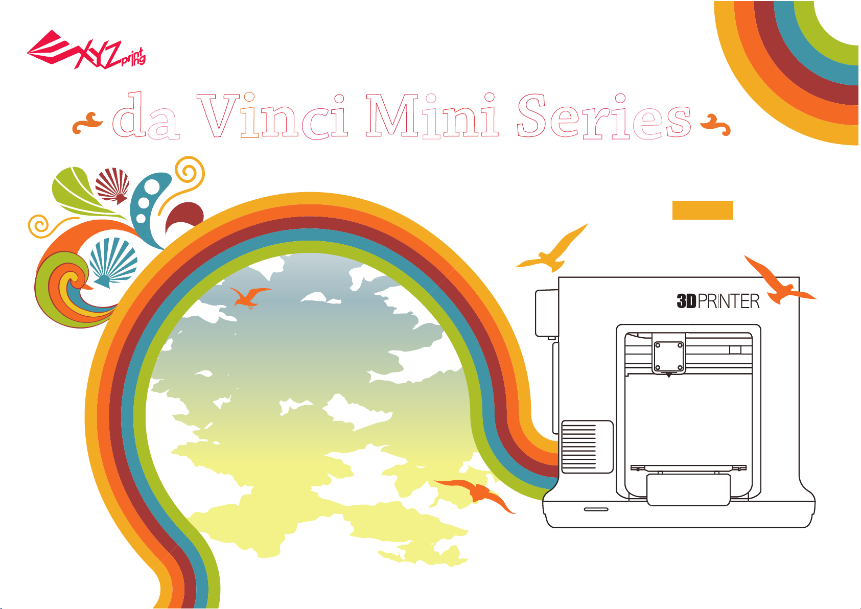
d
a
V
i
n
i M
c
ni Se
i
rie
s
User Manual
English
Specification
Product Overview
Button and Indicator light
Unpacking
Accessory Checklist
Important Safety Notes
Extruder module installation
Accessory installation
XYZware operation
Print
Wi-Fi setup (da Vinci Mini w only)
Advanced XYZware operation
Function descriptions
Using the accessory tools
Print Bed Adjustment
Error message and Action
V1 - 1 -
2
2
2
3
3
3
4
4
6
6
7
10
11
14
15
16
Page 2
1
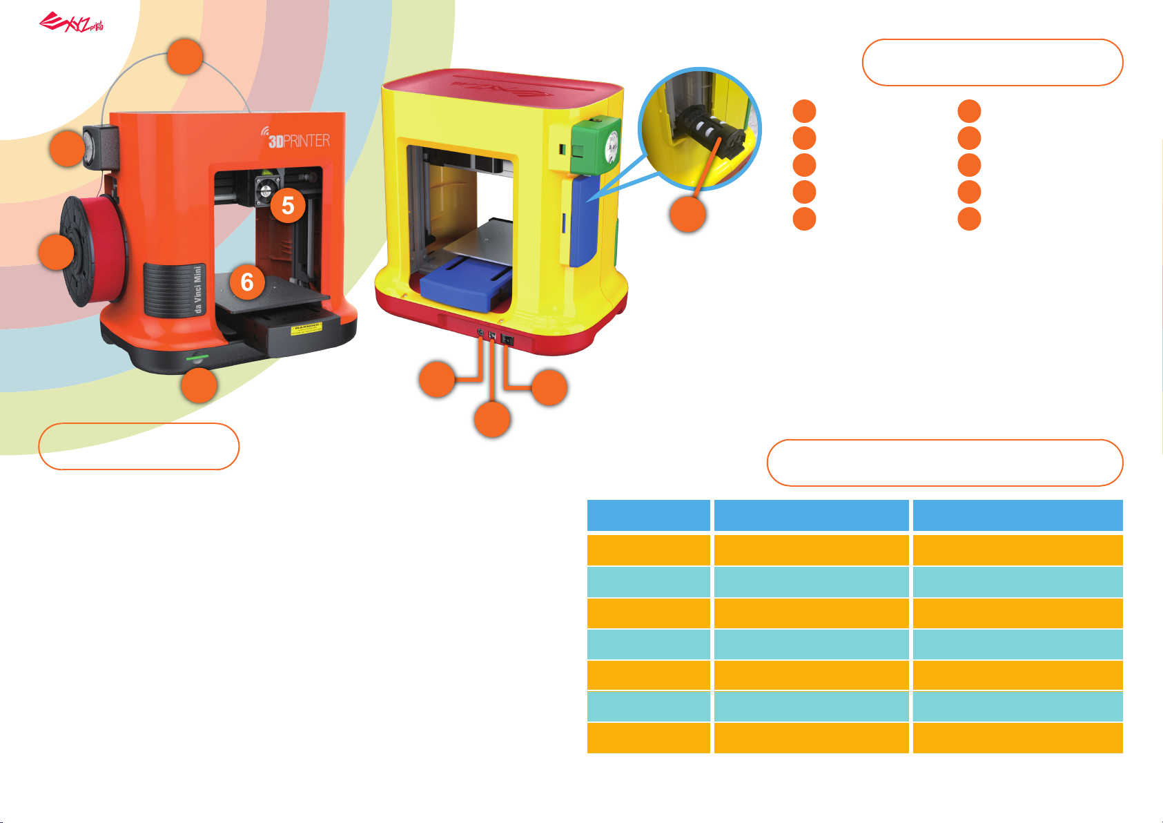
Product Overview
2
3
Specification
Dimensions
Weight
6
4
400 x 336 x 362 mm
8 KG
5
8
9
10
Guide tube
1
Feed module
2
Filament
3
Function button
4
/ status indicator
7
5
Extruder module
Button and Indicator light
Indicator signals Status Action
Print bed
6
Filament holder
7
Power connector
8
9
USB port
10
Power switch
Print Technology
Print Material
Filament Diameter
Nozzle Diameter
Print Dimension
Print Resolution
Connectivity
Print Software
File Format
Fuse Filament Fabrication (FFF)
PLA
1.75 mm
0.4 mm
150 x 150 x 150 mm
0.1/0.2/0.3/0.4mm
USB 2.0 (da Vinci miniMaker)
USB 2.0/ WiFi (da Vinci Mini w)
XYZware
STL / 3W
Solid green
Flashing green
Solid red
Flashing red
Solid orange
Flashing orange
Pulsing orange
If the printer encounters issues, please refer to the XYZware screen troubleshooting instruction to fix
the issues.
Standby/Ready to print
Receiving data
General error
Critical error
Printing
Paused
Job complete (printing complete /
printing cancellation complete)
-
-
Press the button to return to printing status, refer
to instructions in software to fix the issue.
Refer to instructions in the software to solve the
issue or reboot the Mini.
To pause the print, press the button once. To
cancel the print, press and hold the button for 5
seconds.
To resume the print, press the button once.
To return to Ready to print, press the
button once.
- 2 -
Page 3
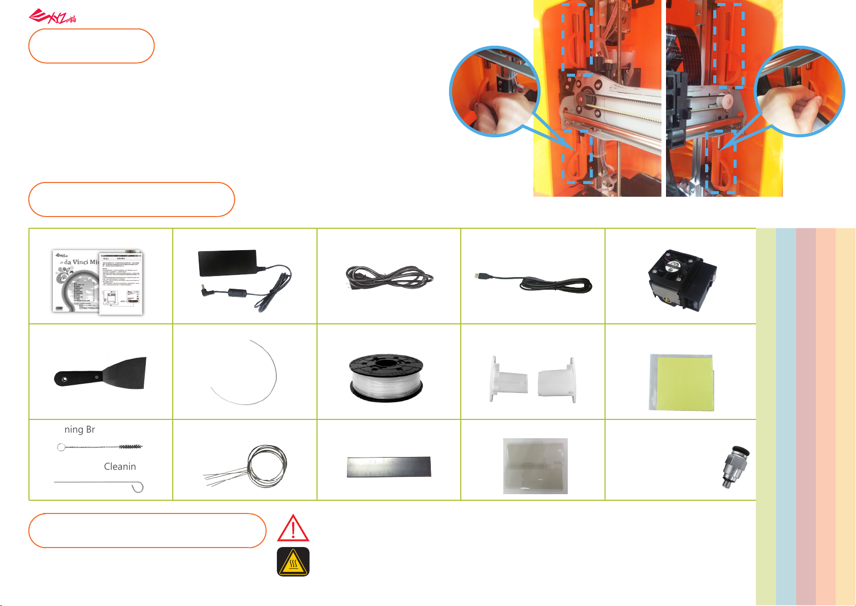
Unpacking
• Before using this printer, remove all fixed materials from the extruder module and
print bed. Switching on the printer without removing these fixed materials may
damage the machine.
• Be sure to remove the 4 clips from the shafts as illustrated on the right.
Notes
Keep original packaging materials in case you need to send your unit back for repair
during the warranty period.
If other packing materials are used instead, the printer may become damaged during transportation.
In such a situation, XYZprinting reserves the right to charge a repair fee.
Accessory Checklist
1. Quick Guide, Warranty Card
6. Scraper
12. Feeding Path Cleaning Wire
2. Power Adapter 3. Power Cord 4. USB Wire 5. Extruder Module
7. Guide Tube 8. Bundled Filament 9. Filament Spool Ring
13. Cleaning Wire x 511. Cleaning Brush
Important Safety Notes
10. Bed Tape X 3pcs (Only replace
(installed on the filament spool)
14. Leveling tool
• Do not use the printer in dusty high humidity or outdoor environments.
• Place the printer on a stable and even surface to avoid it falling and causing serious injury.
• Do not put your hand into the machine during operation to avoid collision risk due to
movement of the machine or to avoid burn due to high temperature.
15. PET Protection cover
the reusable tape when it is worn.)
16. Feeding Tube Grip X1
(For replacing and installing
the Feeding Tube Grip,
please watch the tutorial
video on XYZprinting official
website)
- 3 -
Page 4
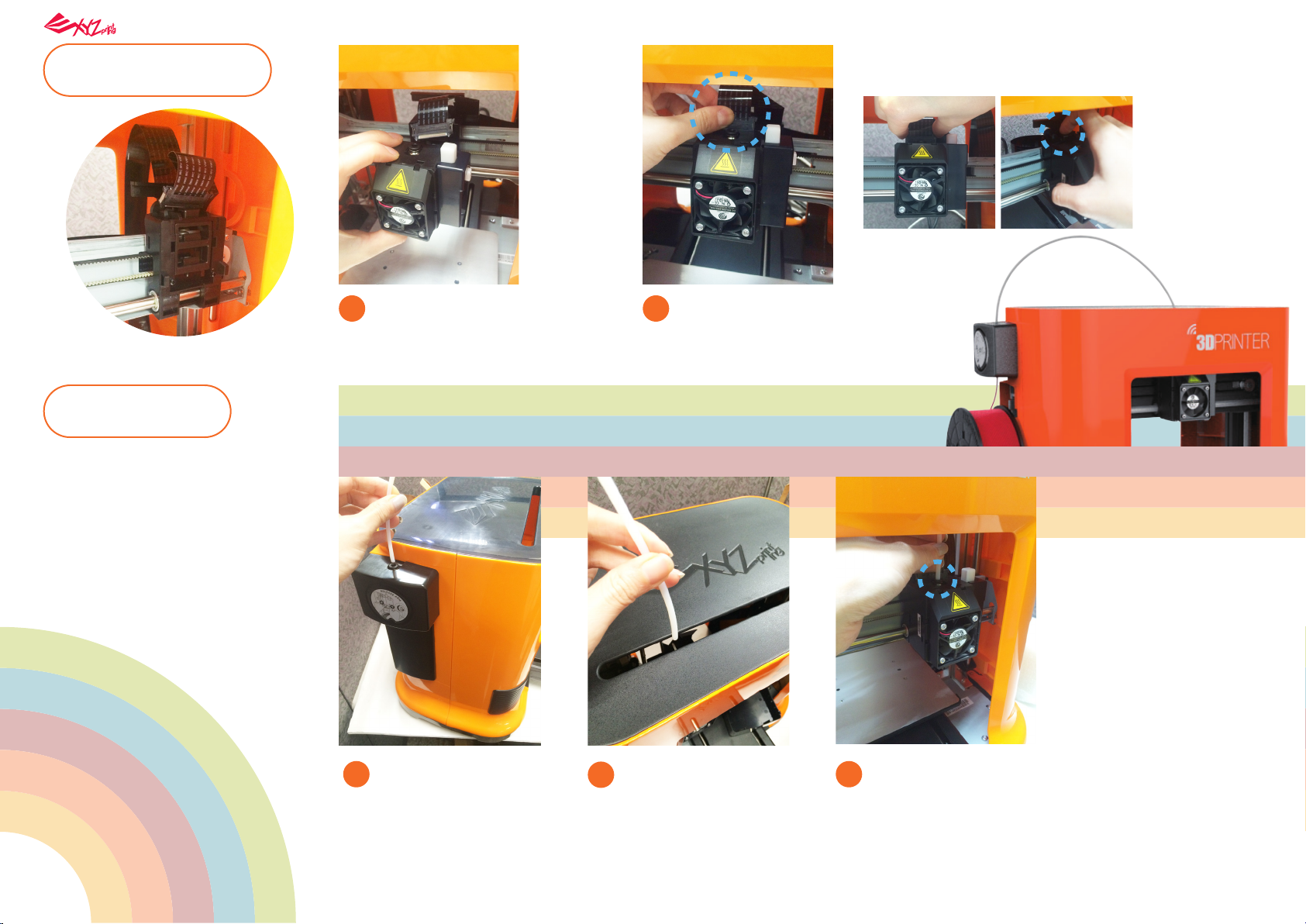
Installing the
Extruder module
NOTE: To unload the extruder module, first detach the
heating bus and press the black disengage button.
Installing the
Accessories
1. Install the guide tube
Make sure that the printer is
1
powered off. Place the extruder
module that the fitting pin is
secured the proper location.
Insert the black ribbon
2
connector to complete
the installation.
Ensure that the guide
1
tube has been tightly
inserted into the port.
Feed the guide tube
2
through the slot at the
top of the printer to
the extruder module.
Ensure that the guide tube
3
is properly inserted into the
feed port of the extruder
module to complete the
installation.
- 4 -
Page 5
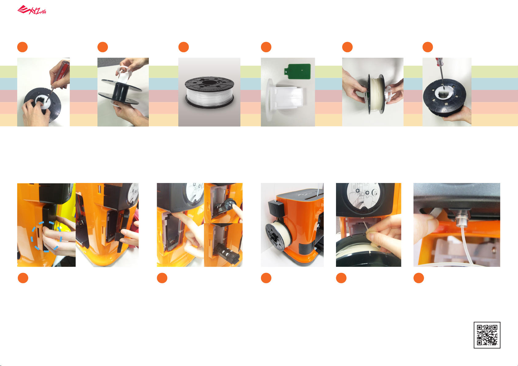
2.Installing the Filament spool ring
21 3 4 5 6
(please refer to this step if the axle ring is not installed on the spool)
Use a phillips screwdriver to loosen the
securing screws of the
filament spool ring.
Separate the spool ring
from both sides of the
spool.
Retrieve the filament
spool and chip.
3.Installing the filament
Remove the side cover by pressing down
1 3
firmly at the center on the left side of the
cover and pushing aside the cover. (pay
attention to where you apply your force to
ensure proper dismantling) Keep the side
cover securely for future use.
Lower the filament spool
2
holder on the left side of
the printer until horizontal.
Install the sensor chip.
Note the orientation of
the sensor chip on the
spool ring.
Place the assembled
filament spool (with
the spool ring) on
the spool holder.
Feed both parts of the
spool ring through the
center hole of the
spool and assemble
them together.
Take the tip of the
4 5
filament and
insert it into the
feeding hole.
Use a phillips screwdriver to tighten and
secure the spool ring
to complete the
installation.
Press the release arm and
push the filament all the
way to the bottom so that
the front end of the
filament is completely
inserted into the extruder
module.
Handy tips
• The filament will load better when the tip of the filament is cut at a 45° angle.
• When the printer is not in use, raise the filament spool holder and close the side cover.
- 5 -
Page 6

XYZware operation
After completing the hardware installation, download XYZware from the XYZprinting official website and install it
on your computer.
Before launching XYZware, connect the printer to your computer using the supplied USB cable and turn it on. For
an optimal user experience, we recommend following the instructions below:
Print
Handy tips
Registration via XYZware before your
first print is strongly recommended.
When registered with XYZprinting, you
will receive latest technical supports
and updates. To register, simply click
"Register Now".
Before you start printing, please attach
the bed tape to the print bed. The print
bed tape is reusable, and can be
replaced worn.
If the room you are printing in is below
25 ℃/ 77 ℉, for greater adhesion,
apply glue to the bed tape.
After printing has started, check if the
first layer is stuck to the print bed.
Good base layer is one of the keys to
successful printing.
Open XYZware
1
Load filament
4
Import 3D file
2
Click Import and select the file to print.
Close Functions panel
5
Open Functions panel
3
Print
6
- 6 -
Page 7

The printing status, including the printing progress,
7
elapsed time, and remaining time, will be shown while
printing. You can pause or cancel the printing task in this
window.
Wi-Fi setup (da Vinci Mini w only)
When done, "Printing Complete"
8
will be shown on screen.
After the print has finished,
9
use a scraper to remove the
printed object.
●Pre-setup
1. The network printing function is only available when the printer and the
computer are both connected to the same wireless network.
2. Before connecting the printer, your wireless network settings need to be
adjusted. For more information, refer to the instruction manual of your
wireless router.
3. The wireless network's channel width needs to be set to 20 MHz for the
printer to connect to it wirelessly. Refer to the vendor instruction manual for
more information.
4. The Mini supports WEP, WPA, and WPA2 security encryption standards.
Wireless pass word information will be requested when setting up the
printer connection.
• WEP • WPA • WPA2
●Setting up Wi-Fi
Connect the printer to your computer with the USB cable, and open
1
"XYZware".
Click the "Printer Monitor" button on the lower right corner on the
2
screen, open "Operation Function".
Select the "Printer Monitor" icon to open the Wi-Fi connection settings.
3
- 7 -
Page 8

In the "Printer Monitor" window, select My
4
Printer > Scan to search for the connected
printer.
Select the USB COM port, click Connect >
5
Establish printer connection.
Click "Wireless Setting"
6
to view wireless print settings.
Enter the printer name, then press the Scan
7 8 9
button.
Use the pull-down menu to view a list of
Wi-Fi connections available in the area, and
select the Wi-Fi connection that you wish to
connect to.
Wait for the printer to obtain the correct
information, provide the wireless password
and press Start wireless connection.
- 8 -
Page 9

Update the printer connection method.
10
XYZware will use the USB connection to
11
update the printer settings.
Once the connection method has been changed from
12
USB to Wi-Fi, you can unplug the USB cable and
continue with the printing process.
OK
Note:
• Name the printer and wireless network with the alphanumeric characters only.
• If no connection is detected within 90 seconds, the printer will time-out. If this is the
case, check that the configuration process is correct and try again.
• Confirm your wireless network's security key on the router's wireless settings page.
- 9 -
Page 10

When using the software to operate the printer, one must first place filament spool ring
pre-loaded with the filament at the axis to activate XYZware.
Click on the Printer Monitoring function at the lower right corner to activate the operating
function.
Then select the Printer Monitoring function icon to activate the USB connection (this step
would be similar to Wi-Fi setup steps 1 to 5).
The USB cable can be removed once the printing file
has been transferred. To monitor printing status,
please re-connect the printer and computer with the
USB cable and re-activate the Printer Monitoring
(function).
If information shown
on-screen is not
updated accordingly,
you may switch off
the operation function screen and then
switch it on again.
(Reload)
Operating the printer with XYZware
A
Import: Import .stl, .3w files
B
Export: Convert to .3w file
C
Save: Save .stl file
D
Print: Set print preference, transfer print file
E
Setting: Set software display language, preview color, Printer Type
About: Query, update software and firmware versions, open link to official website
F
Adjust display scale
G
View: Switch preview angle rapidly
H
Move: Move location of the model
I
Rotate: Change angle of the model
J
Scale: Adjust size of the model
K
Info: Display information about the model
L
Remove: Delete the model from the virtual platform
M
Printer Monitor: Open functio
N
G
H
J
K
L
M
A
B C D E F
I
N
- 10 -
Page 11

Functional descriptions
1
Extruder
Clean Nozzle
Once this function is
selected, the nozzle will
heat up automatically
and move the nozzle to
a proper location
where you can easily
clear away all residual
filaments in the nozzle.
Info
2
Filament
Load Filament Unload Filament
Please follow the on-screen instructions.Please follow the on-screen instructions.
The printing module will automatically move
to the working position. The nozzle will then
heat up to the operating temperature. Please
wait for the extrusion process to finish.
Verify that the nozzle is capable of extruding
the filaments to demonstrate proper loading
of the filaments. If not, please repeat the
filament loading process.
The printing module will automatically
move to the working position. The
nozzle will then heat up to the operating
temperature. Please wait for the unload
filamentprocess to finish.
Info
The extruder module
information, including
Temperature, Nozzle
Diameter, Total Print
Time, and Serial
Number.
Information related to filament use
Note: The end tip of the ejected filament may exhibit
some residual effects. This is considered a normal
phenomenon.
- 11 -
Page 12

3
SetUp
1. Jog Mode
1. Jog Mode
2. Calibrate 3. Z-Offset 4. Others 5. Info
Manually adjust the movement of X/Y/Z Axis for printer maintenance.
First click on [Home Axes]. The printing device will be returned
to the initial axis position at the lower left corner of the printing
area. Then adjust the positions of the printing module (X-AXIS),
printing platform (Y-AXIS), and printing axes (Z-AXIS).
Select “X-AXIS” to move extruder rightwards and leftwards.
Select “Y-AXIS” to move print bed forwards and backwards.
Select “Z-AXIS” to move the print axis (Z-AXIS) upwards and
downwards.
The user may manually enter the adjustment value:
Range: 1 to 150; step: 1 mm
- 12 -
Page 13

2. Calibrate
Platform calibration may be implemented before
the printing process.
The printing device may move to the lower left
corner of the printing area. Please refer to the
platform calibration instructions provided in the
software.
Before calibration, press Button A of the printing
module. After calibration, press Button B on the
printing module in order to retract the sensor
device.
If calibration was faild, please make sure that
Button A (detector) has been pressed before
restarting the calibration process.
Button A
Button B
3. Z-Offset
Upwards and downwards to adjust the printing distance between the
bed and printing module.
Each adjust has a step of 0.05 mm.
If the first layer distance is too high (too large) or too low (too close), we
recommend you using z-offset to adjust the printing distance.
4. Others
●Automatic horizontal calibration
Automatic horizontal calibration may either be ON or OFF. Default: ON.
The software would automatically implement horizontal calibration and
compensation accordingly.
Printing speed may be improved if automatic horizontal calibration has
been switched OFF. However, this may affect printing quality.
●Buzzer
Buzzer is turned on by default, you can select "OFF" to change the
setting.
When the buzzer is turned on, the printer will output an audible signal
when a button is pressed, receiving data, print job is finished, or issue is
detected.
1 2
3 4
5. Info
●Restore Default
Clicks "Restore Default" all settings will be reset to factory default.
Printer Info
Printer Name and
Printer Type
Serial Number
Firmware Version
Total Print Time
Last Time
Connection Info Calibrate Info
Connection Type
Printer IP
WiFi MAC Address
SSID
WiFIi Signal Strength
Calibrate Value
- 13 -
Page 14

Using the accessory
Maintenance Tools
Usage Application method
tools
Scraper
Accessory tools can be used only in an
environment with guidance or monitoring by adult. Do not allow children
to obtain maintenance tools in unfa-
PET Protection cover
miliar situations in order to avoid
danger.
Filament should be unloaded from the extruder before cleaning the feeding path.
Care should be taken during the operation to avoid potential burn injuries.
Taken off the
printing object
Keep your hands
away from the
printing and
operations area
when the machine
is printing.
After print is finished, the printing object may be taken off with Scraper.
Once the PET protective casing has been assembled, apply double sided tape at the
specified locations. Check that the adhesion areas on the printer are clean. Peel away
the carrier film and apply slight pressure to attach the PET casing to the front of the
printer.
Instructions for re-using the double-sided tape of the PET shielding:
Pieces of tape can be re-used if they were kept clean and properly maintained. However,
multiple use or dirt on the tape may reduce the strength of adhesion. Please gently
remove the PET shielding from the printer and then slowly peel away the double-sided
tape from the PET shielding. Do not pull at the tape directly. Stickiness may be restored
by cleaning it with soap water and then drying it.
Cleaning Tools
Feeding Path Cleaning
Wire
Cleaning Brush
Cleaning Wire
Usage Application method
Clean Nozzle
In order to prevent print quality
from impact due to residual and
accumulated filament, which
we recommend you to clean nozzle for every 25
hours of print. Please clamp the nozzle cleaning
wire with needle-nosed pliers to insert it into the
opening of the nozzle carefully for cleaning.
results in poor discharge.
Clean gearwheel
After long periods of use, the
automatic feed system may
have experience unstable
extrusion of the filaments due
The printer filament feed module should be
cleaned after cleaning the nozzle. To do this,
please switch off the power first.
Open the feed module cover and clean the gears
using a gear cleaning brush.
to buildup of residual materials
within the filament channels.
Clean Feeding Path
If the cleaning cycle does not
unclog the extruder, try cleaning the feeding path by useing
the feeding path cleaning wire.
1. Switch on the power and activate the "Clean
Nozzle" function by using the software.
2. Release the extruder module (don't remove the
heating cable at the side).
3. Insert the thick cleaning wire into the feeding
path all the way down and “floss” the inside
of the nozzle to push the residue out.
4. After cleaning the feeding path, reinstall the
extruder module.
- 14 -
Page 15

Print Bed Adjustment
1 2
4
3
Leveling tool T10 screw drivers
1 2
Tools to prepare:
Use Jog Mode and Home Axes functions to
1
move the Z-AXIS to its original position at the
bottom.
Open the cover in front of the left side.
2
Use Jog Mode and move the Z-AXIS upwards
3
by 10 mm.
Manually move the printing module to the right
4
side to prevent affecting its calibrated position.
Place the adjustment tool on the platform
5
directly below the X-AXIS support.
Loosen the 4 screws shown on the diagram.
6
Do not loosen any of the other screws. (Note:
You only need to loosen the screws, not
remove them completely).
Use the Jog Mode and move the Z-AXIS downwards 1 mm at a time until
7
it is completely aligned with the X-AXIS support and calibration tool.
Check that the calibration tool and X-AXIS support are in full-contact
8
with each other, then tighten the 4 loosened screws.
2
At least 10 cm
Within 1-cm diameter
1cm diameter
of the circle
Support Details
As the printer encounters issues, please refer to the following troubleshooting instruction to fix the issues. If the issue cannot be removed, please contact
customer service center.
Maintenance and Service
Keep original packaging material in the event of sending your unit back for repair. If other packing materials are used instead, the printer may be damaged
during the transportation process.. In such situation, the XYZprinting the right to charge repair fee.
- 15 -
Page 16

Error message and Action
In the event of problems, related service code will be shown on the software interface. Please refer to the
description table of the service code for preliminary examination.
Error Code No.
0007
0008
0011
0014
0016
0028
0029
0030
0031
Software interface
Cartridge 1 Error. Please remove cartridge and install again. If errors exist, please
contact service center for support.
Cartridge 1 Error. Please remove cartridge and install again. If errors exist, please
contact service center for support.
Heating Error.
Please turn off the printer and contact service center for support.
Heating Error.
Please turn off the printer and contact service center for support.
Cartridge 1 not installed properly. Please reinstall Cartridge 1 ("Unload Filament" then
"Load Filament") on your printer. If error persists, please contact service center for
further support.
Cartridge 1 can not be found. Please install one.
There is no filament left in Cartridge 1. Please replace Cartridge 1 before printing.
Printer motor Error(X-Axis)
If errors exist, please contact service center for support.
Printer motor Error(Y-Axis)
If errors exist, please contact service center for support.
Action
Reinstall or replace the filament cartridge.
Reinstall or replace the filament cartridge.
Check whether the connections are connected properly and restart as
required.
Check whether the connections are connected properly and restart as
required.
Reinstall the filament cartridge.
Reload or replace the filament.
Replace filament immediately.
Check motor/sensor connections. Check sensor position.
Check motor/sensor connections. Check sensor position.
0032
0051
0052
0054
0201
020D
Printer motor Error(Z-Axis)
If errors exist, please contact service center for support.
Flash ram cannot be read/written.
Memory in the extruder cannot be read/written.
Incompatible Nozzle Turn off printer and reinstall compatible nozzle, then turn your printer
Computer and printer connection issues.
File is printable by: da Vinci XXX
Check motor/sensor connections. Check sensor position.
Reboot the printer.
Replace the nozzle.
back on. If this error persists, please contact service center.
Re-connect the computer with the printer. Alternatively, you may use
hot plugging of the USB cable to connect the computer with the
printer.
This shows that this file type is not supported. Please select a proper
printer model instead.
- 16 -
 Loading...