

Davin Toscana-C1b, Toscana-C1a, J014, Toscana-C1bN, J012 Service Manual
...
Toscana-C1a/C1b/C1bN
Machine Code: J012/J013/J014
SERVICE MANUAL
July 2007
Subject to change

Safety Instructions
For your safety, please read this manual carefully before you service machine. Always keep this manual
handy for future reference.
Safety Information
Always obey these safety precautions when using this product.
Switches and Symbols
Where symbols are used on or near switches on machines for Europe and other areas, the meaning of
each symbol conforms with IEC60417.
Responsibilities of the Customer Engineer
Maintenance
Maintenance shall be done only by trained customer engineers who have completed service training for
the machine and all optional devices designed for use with the machine.
Installation
The main machine and options can be installed by either the customer or customer engineer. The customer
or customer engineer must follow the installation instructions described in the operating instructions.
Reference Material for Maintenance
Maintenance shall be done with the special tools and the procedures prescribed for maintenance of the
machine described in the reference materials (service manuals, technical bulletins, operating instructions,
and safety guidelines for customer engineers).
• Use only consumable supplies and replacement parts designed for use with the relevant machine.
1

Before Installation, Maintenance
Shipping and Moving the Machine
• Work carefully when lifting or moving the machine. If the machine is heavy, two or more customer
engineers may be required to prevent injuries (muscle strains, spinal injuries, etc.) or damage to the
machine if it is dropped or tipped over.
• Personnel moving or working around the machine should always wear proper clothing and footwear.
Never wear loose fitting clothing or accessories (neckties, loose sweaters, bracelets, etc.) or casual
footwear (slippers, sandals, etc.) when lifting or moving the machine.
• Always unplug the power cord from the power source before you move the machine. Before you
move the machine, arrange the power cord so it will not fall under the machine.
Power
• Always turn the machine off and disconnect the power plug before doing any maintenance procedure.
After turning the machine off, power is still supplied to the main machine and other devices. To prevent
electrical shock, switch the machine off, wait for a few seconds, and then unplug the machine from
the power source.
• Before you do any checks or adjustments after turning the machine off, work carefully to avoid injury.
After removing covers or opening the machine to do checks or adjustments, avoid touching electrical
components or moving parts (gears, timing belts, etc.).
• After turning the machine on with any cover removed, keep your hands away from electrical
components and moving parts. Never touch the cover of the fusing unit, gears, timing belts, etc.
Installation, Disassembly, and Adjustments
• After installation, maintenance, or adjustment, always check the operation of the machine to make
sure that it is operating normally. This ensures that all shipping materials, protective materials, wires
and tags, metal brackets, etc., (attached to protect the machine during shipping), have been removed
and that no tools remain inside the machine.
• Never use your fingers to check moving parts that are causing spurious noise. Never use your fingers
to lubricate moving parts while the machine is operating.
2

Special Tools
• Use only standard tools approved for machine maintenance.
• For special adjustments, use only the special tools and lubricants described in the service manual.
Using tools incorrectly, or using tools that could damage parts, could damage the machine or cause
injuries.
During Maintenance
General
• Before you begin a maintenance procedure always switch the machine off.
• Disconnect the power plug from the power source.
• Allow the machine to cool for at least 10 minutes.
• Avoid touching the components inside the machine that are labeled as hot surfaces.
Safety Devices
• Never remove any safety device (a fuse, thermistor, etc.) unless it requires replacement. Always
replace a safety device immediately.
• Never do any procedure that defeats the function of any safety device. Modification or removal of a
safety device (fuse, thermistor, etc.) could cause a fire and personal injury. After removal and
replacement of any safety device, always test the operation of the machine to ensure that it is operating
normally and safely.
• For replacement parts use only the correct fuses, thermistors, circuit breakers, etc. rated for use with
the machine. Using replacement devices not designed for use with the machine could cause a fire
and personal injuries.
Organic Cleaners
• During preventive maintenance, never use any organic cleaners (alcohol, etc.) other than those
described in the service manual. (Refer the “2. Preventive Maintenance” in the Service Manual.)
• Make sure the room is well ventilated before using any organic cleaner. Always use organic solvents
in small amounts to avoid breathing the fumes and becoming nauseous.
3

• Switch the machine off, unplug it, and allow it to cool before doing preventive maintenance. To avoid
fire or explosion, never use an organic cleaner near any component that generates heat.
• Wash your hands thoroughly after cleaning parts with an organic cleaner to avoid contamination of
food, drinks, etc. which could cause illness.
Power Plug and Power Cord
• Before servicing the machine (especially when responding to a service call), always make sure that
the power plug has been inserted completely into the power source. A partially inserted plug could
lead to heat generation (due to a power surge caused by high resistance) and cause a fire or other
problems.
• Always check the power plug and make sure that it is free of dust and lint. Clean it if necessary. A
dirty plug can generate heat and cause a fire.
• Inspect the entire length of the power cord for cuts or other damage. Replace the power cord if
necessary. A frayed or otherwise damaged power cord can cause a short circuit which could lead
to a fire or personal injury from electrical shock.
• Check the length of the power cord between the machine and power supply. Make sure the power
cord is not coiled or wrapped around any object such as a table leg. Coiling the power cord can
cause excessive heat to build up and could cause a fire.
• Make sure that the area around the power source is free of obstacles so the power cord can be
removed quickly in case of an emergency.
• Make sure that the power cord is grounded (earthed) at the power source with the ground wire on
the plug.
• Connect the power cord directly into the power source. Never use an extension cord.
• When you disconnect the power plug from the power source, always pull the plug, not the cable.
After Installation Servicing
Disposal of Used Items
• Ink is flammable. Never attempt to incinerate empty ink cartridges.
• Always dispose of used items in accordance with the local laws and regulations regarding the disposal
of such items.
4

• To protect the environment, never dispose of this product or any kind of waste from consumables at
a household waste collection point. Dispose of these items at one of our dealers or at an authorized
collection site.
Points to Confirm with Operators
At the end of installation or a service call, instruct the user about use of the machine. Emphasize the following
points.
• Show operators how to remove jammed paper and troubleshoot other minor problems by following
the procedures described in the operating instructions.
• Point out the parts inside the machine that they should never touch or attempt to remove.
• Confirm that operators know how to store and dispose of consumables such as ink cartridges,
ammonia water, paper, etc.
• Make sure that all operators have access to an operating instruction manual for the machine.
• Confirm that operators have read and understand all the safety instructions described in the operating
instructions.
• Demonstrate how to turn off the power and disconnect the power plug (by pulling the plug, not the
cord) if any of the following events occur:
1. Something has spilled into the product.
2. Service or repair of the product is necessary.
3. The product cover has been damaged.
• Caution operators about removing paper fasteners around the machine. They should never allow
paper clips, staples, or any other small metallic objects to fall into the product.
• Make sure the operators understand the following points:
• The operator must lift the output tray to release the paper cassette before loading paper.
• Paper is loaded in the standard paper cassette without removing it from the machine.
• The operator should never attempt to remove the paper cassette from the machine.
Special Safety Instructions For Ink Cartridges
Accidental Exposure To Ink
• If ink gets on the skin, wash the affected area immediately with soap and cold running water.
5

• If ink gets into the eyes, immediately flush the eyes with cold running water. If there are signs of irritation
or other problems, seek medical attention.
• If ink is swallowed, drink a strong solution of cold water and table salt to induce vomiting. Seek medical
attention immediately.
• Ink is difficult to remove from fabric. Work carefully to avoid staining clothing when performing routine
maintenance or replacing cartridges.
Handling and Storing Ink Cartridges
• Ink is flammable. Never store ink cartridges in a location where they will be exposed to high
temperature or an open flame.
• Always store ink cartridges out of the reach of children.
• Always store ink cartridges in a cool, dry location that is not exposed to direct sunlight.
Ink Cartridge Disposal
• Attach the caps to empty ink containers for temporary storage to avoid accidental spillage.
• Return empty ink cartridges to a local dealer who can accept such items for collection and recycling
or disposal.
• If the customer decides to dispose of empty ink cartridges, make sure that they are disposed of in
accordance with local laws and regulations.
Safety Instructions for This Machine
Introduction
• This manual contains detailed instructions and notes on the operation and use of this machine. For
your safety and benefit, read this manual carefully before using the machine. Keep this manual in a
handy place for quick reference.
• Important
• Contents of this manual are subject to change without prior notice. In no event will the company be
liable for direct, indirect, special, incidental, or consequential damages as a result of handling or
operating the machine.
• Do not copy or print any item for which reproduction is prohibited by law.
6

• Copying or printing the following items is generally prohibited by local law: bank notes, revenue
stamps, bonds, stock certificates, bank drafts, checks, passports, driver's licenses.
• The preceding list is meant as a guide only and is not inclusive. We assume no responsibility for its
completeness or accuracy. If you have any questions concerning the legality of copying or printing
certain items, consult with your legal advisor.
• This machine is equipped with a function that prevents making counterfeit bank bills. Due to this function
the original images similar to bank bills may not be copied properly.
• Some illustrations in this manual might be slightly different from the machine.
• For good print quality, the supplier recommends that you use genuine print cartridges from the supplier.
• The supplier shall not be responsible for any damage or expense that might result from the use of parts
other than genuine parts from the supplier with your office products.
Power Source
• 220-240 V or more, 50 / 60 Hz, A or more
• Voltage must not fluctuate more than 10%.
• Please be sure to connect the power cable to a power source as above.
• Confirm that the wall outlet is near the machine and freely accessible, so that in event of an emergency,
it can be un-plugged easily.
• Disconnect the power plug (by pulling the plug, not the cable) if the power cable or plug becomes
frayed or otherwise damaged.
• The supplied power cord is for use with this equipment only. Do not use with other appliances. Doing
so may result in fire, electric shock, or injury.
• Connect the machine only to the power source described on the inside front cover of this manual.
Connect the power cord directly into a wall outlet and do not use an extension cord.
• Avoid multi-wiring.
• Do not damage, break or make any modifications to the power cord. Do not place heavy objects on
it. Do not pull it hard nor bend it more than necessary. These actions could cause an electric shock or
fire.
• Do not plug or unplug the power cord with your hands wet. Otherwise, an electric shock might occur.
• To avoid hazardous electric shock, do not remove any covers or screws other than those specified in
this manual. When the machine needs to be checked, adjusted, or repaired, contact your service
representative.
• Do not take apart or attempt any modifications to this machine. There is a risk of fire, electric shock,
explosion or loss of sight. If by any chance this machine falls over or a breakage occurs (e.g. the
cover), turn off the main switch, unplug the power cable and contact your service representative. If
you continue to use the machine in this state it could result in fire or electric shock.
7

• If metal, liquid or foreign matter falls into the machine, turn off the operation and main power switches,
and unplug the main power cord. Contact your service representative. Do not keep using the machine
with a fault or defect.
• If the power cord is damaged (exposure of the core, disconnection, etc.), contact your service
representative to change to a new one. Operating the machine with a damaged power cord may
cause an electric shock or fire.
• Do not put any metal objects or containers holding water (e.g. vases, flowerpots, glasses) on the
machine. If the contents fall inside the machine, a fire or electric shock could occur.
• Keep the machine away from flammable liquids, gases, and aerosols. A fire or an electric shock might
occur.
• Disposal can take place at our authorized dealer.
• Dispose of used ink containers in accordance with local regulations.
• The wall outlet shall be installed near the machine and shall be easily accessible.
• Protect the machine from dampness or wet weather, such as rain and snow.
• Keep the machine away from humidity and dust. Otherwise a fire or an electric shock might occur.
• Do not place the machine on an unstable or tilted surface. If it topples over, an injury might occur.
• If you use the machine in a confined space, make sure there is a continuous air turnover.
• Unplug the power cord from the wall outlet before you move the machine. While moving the machine,
you should take care that the power cord will not be damaged under the machine.
• Before moving the machine, be sure to disconnect all external connections, especially the power cord
from the wall outlet. Damaged power cords are a fire and electric shock hazard.
• When the machine will not be used for a long time, unplug the power code.
• When you disconnect the power plug from the wall outlet, always pull the plug (not the cable).
• Our products are engineered to meet high standards of quality and functionality, and we recommend
that you use only the expendable supplies available at an authorized dealer.
• Deliver to waste product collection areas. Do not dispose of via domestic refuse collection.
• The Toscana-C1a weighs approximately 20 kg (44 lb.), the Toscana-C1b 23 kg (50.7 lb.), and the
Tocana-C1bN 23.5 kg (51.8 lb.)
• When moving the machine, use the indented sections on the side's lower edge, and lift slowly.
• During operation, rollers for transporting the paper and originals revolve. A safety device is being
installed so that the machine can be operated safely. But take care not to touch the machine during
operation. An injury might occur.
• When the optional paper tray unit is installed, do not push the upper part of the main unit horizontally.
An injury might occur if the paper tray unit becomes detached from the main unit.
8

• For environmental reasons, do not dispose of the machine or expended supply waste at household
waste collection points. Disposal can take place at an authorized dealer.
• If ink or used ink is inhaled, gargle with plenty of water and move into a fresh air environment. Consult
a doctor if necessary.
• If ink is ingested, induce vomiting by drinking a strong saline solution. Consult a doctor immediately.
• If ink gets into your eyes, immediately rinse your eyes under running water. Consult a doctor if you
have a problem.
• Avoid getting ink on your clothes or skin when removing a paper jam or replacing ink cartridges. If
your skin comes into contact with ink, wash the affected area thoroughly with soap and water.
• If ink gets on your clothing, wash with cold water. Hot water will set the ink into stain impossible.
• Keep the ink or ink container out of reach of children.
• Do not look into the lamp - it can damage your eyes.
• Rating voltage of the connector for option: Max. DC 37 V.
• When you use this machine for a long time in a confined space without good ventilation, you may
detect an odd smell. To keep the workplace comfortable, we recommend that you keep it well
ventilated.
9
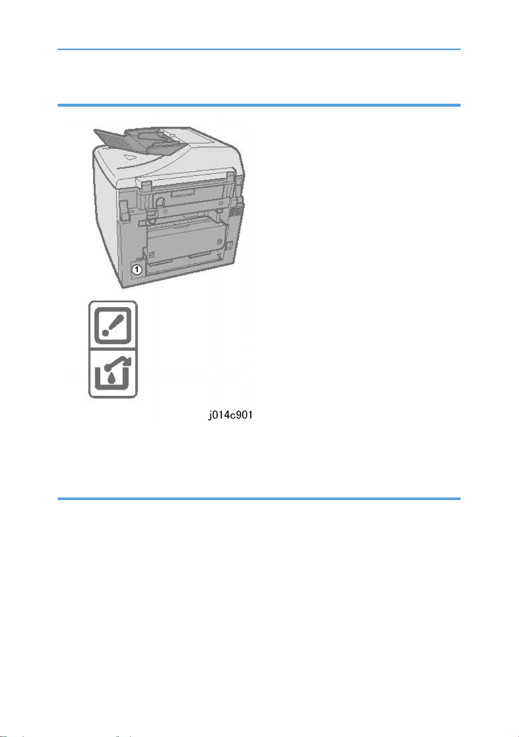
Ink Collection Caution Labels
Caution labels are affixed on the ink collector unit ¬ to remind you to handle it carefully to avoid ink
spillage.
User Information on Electrical & Electronic Equipment
Users in the EU, Switzerland and Norway
• Our Products contain high quality components and are designed to facilitate recycling.
• Our products or product packaging are marked with the symbol below.
10

• The symbol indicates that the product must not be treated as municipal waste. It must be disposed of
separately via the appropriate return and collection systems available. By following these instructions
you ensure that this product is treated correctly and help to reduce potential impacts on the
environment and human health, which could otherwise result from inappropriate handling. Recycling
of products helps to conserve natural resources and protect the environment.
• For more detailed information on collection and recycling systems for this product, please contact the
shop where you purchased it, your local dealer or sales/service representatives.
All Other Users
• If you wish to discard this product, please contact your local authorities, the shop where you bought
this product, your local dealer or sales/service representatives.
International ENERGY STAR® Office Equipment Program
• The International ENERGY STAR® Office Equipment Program encourages energy conservation by
promoting energy efficient computers and other office equipment.
• The program backs the development and dissemination of products that feature energy saving
functions.
• It is an open program in which manufacturers participate voluntarily.
• Targeted products are computers, monitors, printers, facsimiles, copiers, scanners, and multifunction
devices. Energy Star standards and logos are internationally uniform.
11

• Never attempt to replace a battery on a printed circuit board. Replacing a battery with the incorrect
type could cause the battery to explode. If there is a problem with a circuit board replace the entire
board as a single unit.
• Always obey the local laws and regulations regarding the disposal of used batteries, PCBs and other
electrical components.
12
Conventions Used in This Manual
Machine References
This service manual describes servicing and maintenance of the three Toscana-C1 machines:
Toscana-C1a (J012), Toscana-C1b (J013), and Toscana-C1bN (J014). The "Model No." is not used in
this Service Manual.
Machine
No.
J012 Toscana-C1a GX3000S
J013 Toscana-C1b GX3000SF NIB an option (requires installation).
J014 Toscana-C1bN GX3000SFN NIB standard (no NIB installation required)
The following options are available for the J012, J013, and J014.
No. Option Name For Machine
J509 Paper Feed Unit TK2000 J012/J013/J014
J507 Multi Bypass Tray Type BY1000 J012/J013/J014
J510 Network Interface Board Type GX4 J012/J013 (Standard for J014)
• The duplex unit attached to the back of the machine is standard for the J012/J013/J014 and must
always remain installed for the machines to operate properly. The duplex unit can be easily removed,
however, for servicing.
Production Name Model No. Comments
No ARDF, no fax, NIB is an option (requires
installation)
The J012/J013/J014 machines are provided with four starter print cartridges for installation. Thereafter,
the following print cartridges are used for all three machines.
No. Name
J737 Print Cartridge GC 21Y
J736 Print Cartridge GC 21M
J735 Print Cartridge GC 21C
13

No. Name
J734 Print Cartridge GC 21K
Operation Panel Procedures
Symbol What It Means
[ ] Square brackets denote keys on the operation panel.
[107]
[Form Feed]*[Clear/Stop] The asterisk indicates keys that should be pressed at the same time.
>
" "
[] or [] Press either the up or down arrow on the scroll key
[] or [] Press either the left or right arrow on the scroll key.
Example
Machine operation panel procedures are abbreviated to reduce the needless repetition of words and
make procedures easier to read.
What You See What This Means
1.[Menu] 1. Press the [Menu] key.
2. [] or [] > "System Settings?" > [Yes].
Press the [1] key and release, press the [2] and release, then press the
[7] key and release.
A right angle bracket denotes what should appear on the display, or
the next key to press.
Quotation marks denote items (selections, messages, etc.) that appear
for selection on the display panel of the machine.
2. Press either the [] or [] key to display
"System Settings" then press the [Yes] key.
14
3. [] or [] > "Language?" > [Yes]
4. [] or [] to select the desired language > [Yes]
5. [No] to return to the previous display.
3. Press either the [] or [] key to display
"Language" then press the [Yes] key.
4. Press either the [] or [] to show the
desired language then press the [Yes] key.
5. Press the [No] key to return to the previous
display..
What You See What This Means
6. [Clear Modes] to return to standby.
6. Press [Clear Modes] to close the menu and
return to the standby (operation) mode.
Graphic Symbols and Abbreviations
This manual uses several symbols in section "3. Replacement and Adjustment".
Symbol What It Means
Screw
Connector
E-ring
Clip ring
Clamp
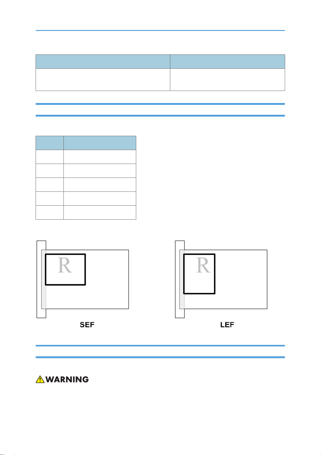
This manual uses SEF (Short Edge Feed) and LEF (Long Edge Feed) to denote paper orientation.
Warnings, Cautions, Notes
In this manual, the following important symbols and notations are used.
• A Warning indicates a potentially hazardous situation. Failure to obey a Warning could result in
death or serious injury.
15

• A Caution indicates a potentially hazardous situation. Failure to obey a Caution could result in minor
or moderate injury or damage to the machine or other property.
• Obey these guidelines to avoid problems such as misfeeds, damage to originals, loss of valuable
data and to prevent damage to the machine
• This information provides tips and advice about how to best service the machine.
Trademarks
• Microsoft®, Windows®, Windows Server® and VistaTM® are registered trademarks of Microsoft
Corporation in the United States and /or other countries.
• PostScript® is a registered trademark of Adobe Systems, Incorporated.
• PCL® is a registered trademark of Hewlett-Packard Company.
• Ethernet® is a registered trademark of Xerox Corporation.
• PowerPC® is a registered trademark of International Business Machines Corporation.
• Other product names used herein are for identification purposes only and may be trademarks of their
respective companies. We disclaim any and all rights involved with those marks.
16

TABLE OF CONTENTS
Safety Instructions...............................................................................................................................................1
Responsibilities of the Customer Engineer....................................................................................................1
Before Installation, Maintenance..................................................................................................................2
During Maintenance......................................................................................................................................3
After Installation Servicing.............................................................................................................................4
Special Safety Instructions For Ink Cartridges..............................................................................................5
Safety Instructions for This Machine..............................................................................................................6
Conventions Used in This Manual..................................................................................................................13
Machine References....................................................................................................................................13
Operation Panel Procedures.......................................................................................................................14
Graphic Symbols and Abbreviations.........................................................................................................15
Warnings, Cautions, Notes........................................................................................................................15
Trademarks...................................................................................................................................................16
1. Installation
Preparation.......................................................................................................................................................25
Environment..................................................................................................................................................25
Choosing a Location....................................................................................................................................25
Minimum Space Requirements...................................................................................................................26
Power Source...............................................................................................................................................27
Computer Hardware and Software...........................................................................................................27
Using the Operation Panel..............................................................................................................................29
Summary of Important Operation Panel Keys...........................................................................................29
Entering Text.................................................................................................................................................31
Quick Summary of Important Procedures..................................................................................................33
Installation Procedure......................................................................................................................................36
What You Need...........................................................................................................................................36
Accessory Check..........................................................................................................................................36
Remove the Shipping Material...................................................................................................................37
Carrying the Printer......................................................................................................................................38
Install the Print Cartridges............................................................................................................................41
Load Paper...................................................................................................................................................43
Connect the Power Cord.............................................................................................................................45
Complete the Installation.............................................................................................................................46
17

Install USB and Printer Driver......................................................................................................................48
Options.............................................................................................................................................................51
Paper Feed Unit...........................................................................................................................................51
Multi Bypass Tray J507...............................................................................................................................53
Network Interface Board J510...................................................................................................................55
Important Information......................................................................................................................................59
Checklist Before Moving the Machine.......................................................................................................59
If the Machine Is Not Used Frequently…...................................................................................................59
Moving the Printer........................................................................................................................................60
2. Preventive Maintenance
PM Table...........................................................................................................................................................63
Service Call Procedures..............................................................................................................................63
Regular Cleaning.........................................................................................................................................64
3. Replacement and Adjustment
Before Replacing Parts.....................................................................................................................................65
Removal Table.............................................................................................................................................65
Important Notice..........................................................................................................................................68
Procedure Summary....................................................................................................................................69
Common Procedures........................................................................................................................................73
Network Interface Board (NIB)..................................................................................................................73
Duplex Unit...................................................................................................................................................73
Ink Collector Unit.........................................................................................................................................74
Platen (J012 only)........................................................................................................................................76
ADF (J013/J014)........................................................................................................................................76
Original Pressure Plate................................................................................................................................77
Scanner to Full Upright................................................................................................................................78
Paper Cassette, Output Tray.......................................................................................................................79
Right Front Cover.........................................................................................................................................80
Right Cover...................................................................................................................................................81
Right Inner Cover.........................................................................................................................................82
Left Cover......................................................................................................................................................84
Front Cover...................................................................................................................................................85
Scanner Unit.................................................................................................................................................86
18

Rear Cover...................................................................................................................................................91
Flushing Unit......................................................................................................................................................93
Maintenance Unit.............................................................................................................................................94
Encoders...........................................................................................................................................................96
Vertical Encoder Wheel..............................................................................................................................96
Horizontal Encoder Strip.............................................................................................................................98
Boards............................................................................................................................................................101
PSU.............................................................................................................................................................101
HVPS...........................................................................................................................................................102
Printer Engine CTL Board, NVRAM.........................................................................................................103
Duplex Unit Detection Board....................................................................................................................108
Motors............................................................................................................................................................109
Horizontal Motor.......................................................................................................................................109
Vertical Motor............................................................................................................................................111
Maintenance Unit Motor..........................................................................................................................112
Rear Fan.....................................................................................................................................................114
Front Fan....................................................................................................................................................115
Sensors...........................................................................................................................................................116
Vertical Encoder Sensor............................................................................................................................116
Carriage Position Sensor..........................................................................................................................117
Ink Level Sensor.........................................................................................................................................118
1st Registration Sensor..............................................................................................................................119
2nd Registration Sensor............................................................................................................................120
Scanner Unit Sensor..................................................................................................................................122
Air Release Solenoid.....................................................................................................................................123
Cleaning Procedures.....................................................................................................................................124
Flushing Gate Cleaning............................................................................................................................125
Maintenance Unit Cleaning.....................................................................................................................125
Feed Roller Cleaning................................................................................................................................127
Transport Belt Cleaning............................................................................................................................128
Friction Pad Cleaning................................................................................................................................128
Horizontal Encoder Strip Cleaning..........................................................................................................129
Swapping the Engine Unit.............................................................................................................................132
19

Firmware Update...........................................................................................................................................133
What You Need........................................................................................................................................133
4. Troubleshooting
Display Summary...........................................................................................................................................141
Operation Panel Display..........................................................................................................................141
Display Menu Summary...........................................................................................................................141
Status Reports.................................................................................................................................................150
1. Page Counter........................................................................................................................................151
2. System Summary (Config. List).............................................................................................................152
3. Engine Summary Chart.........................................................................................................................153
4. Service Data List....................................................................................................................................155
5. T.30 Protocol List...................................................................................................................................156
Self-Diagnostic Test Flow..............................................................................................................................157
SC Error Codes..............................................................................................................................................160
Summary of Error Levels...........................................................................................................................160
Out-of-Range Temperature Errors...........................................................................................................160
SC Code Tables........................................................................................................................................161
Jam Codes.................................................................................................................................................164
Facsimile Errors..........................................................................................................................................172
Image Correction...........................................................................................................................................179
Preparing for Test Printing.........................................................................................................................179
Nozzle Check............................................................................................................................................179
Print Head Cleaning..................................................................................................................................180
Print Head Flushing....................................................................................................................................181
Adjust Paper Feed.....................................................................................................................................181
Head Position.............................................................................................................................................183
Registration................................................................................................................................................184
Drive Cleaning...........................................................................................................................................186
Cleaning the Printheads Before Storage.................................................................................................187
Quick Reference............................................................................................................................................190
5. Service Tables
Before You Begin...........................................................................................................................................199
Service Mode............................................................................................................................................199
20

SP Mode....................................................................................................................................................200
Service Mode.................................................................................................................................................204
Access to Service Mode ..........................................................................................................................204
Service Mode Menus................................................................................................................................205
SP Mode Service Tables...............................................................................................................................230
SP Table Key..............................................................................................................................................230
Group 1000..............................................................................................................................................231
Group 2000..............................................................................................................................................243
Group 3000..............................................................................................................................................246
Group 4000..............................................................................................................................................248
Group 5000..............................................................................................................................................249
Group 6000..............................................................................................................................................256
Group 7000..............................................................................................................................................256
Bit Switches.....................................................................................................................................................270
Changing Bit Switch Settings....................................................................................................................270
Bit Switch Summary...................................................................................................................................270
6. Detailed Section Descriptions
Important Parts...............................................................................................................................................275
J012...........................................................................................................................................................275
J013/J014................................................................................................................................................278
Boards............................................................................................................................................................281
Board Circuit Diagram..............................................................................................................................281
Board Layout Diagram..............................................................................................................................282
Electrical Components...................................................................................................................................283
Overview....................................................................................................................................................283
Electrical Component Summary...............................................................................................................288
Print Heads.....................................................................................................................................................296
Overview....................................................................................................................................................296
Print Head..................................................................................................................................................296
Print Head Tank.........................................................................................................................................297
Ink Ejection Device....................................................................................................................................298
Ink Near End..............................................................................................................................................299
Ink Out........................................................................................................................................................300
21

Registration Sensors..................................................................................................................................300
Ink....................................................................................................................................................................302
Viscous ink (liquid gel)..............................................................................................................................302
Wide Print Head........................................................................................................................................302
Belt Transfer System..................................................................................................................................303
Level Color Mode.....................................................................................................................................304
Ink Supply.......................................................................................................................................................305
Overview....................................................................................................................................................305
Print Cartridges..........................................................................................................................................306
Print Cartridge Set Sensors.......................................................................................................................307
Ink Pumps...................................................................................................................................................308
Print Heads.................................................................................................................................................309
Print Head Maintenance...........................................................................................................................311
Maintenance Unit......................................................................................................................................311
Print Head Maintenance Cycles..............................................................................................................316
Ink Collector Tank......................................................................................................................................317
Ink Collector Ink level sensor....................................................................................................................318
Flushing Unit...............................................................................................................................................319
Carriage Drive...............................................................................................................................................320
Overview....................................................................................................................................................320
Envelope Selector......................................................................................................................................321
Paper Feed, Transport, Paper Exit................................................................................................................322
Overview....................................................................................................................................................322
Cassette Lock/Release.............................................................................................................................323
Leading Edge and Paper Size Detection.................................................................................................323
Paper Jam, Trailing Edge Detection.........................................................................................................324
Paper Transport Drive...............................................................................................................................324
Paper Path..................................................................................................................................................325
Transport Belt.............................................................................................................................................326
Charge Leak Detection.............................................................................................................................327
Cooling Fan...............................................................................................................................................328
Scanner Unit Switch..................................................................................................................................328
Basic Operation.............................................................................................................................................329
22

Initialization Sequence at Power On.......................................................................................................329
Image Processing...........................................................................................................................................330
Duplex Unit.....................................................................................................................................................331
Overview....................................................................................................................................................331
Duplex Drive..............................................................................................................................................331
Duplexer Cover Switch.............................................................................................................................332
Duplexer Set Switch..................................................................................................................................333
Multi Bypass Tray (Option)...........................................................................................................................334
Paper Feed Unit (Option)..............................................................................................................................336
Overview....................................................................................................................................................336
Paper Feed.................................................................................................................................................337
ADF.................................................................................................................................................................338
Overview....................................................................................................................................................338
Drive...........................................................................................................................................................338
7. Specifications
General Specifications..................................................................................................................................341
ADF.............................................................................................................................................................341
Scanner......................................................................................................................................................341
General Specifications..............................................................................................................................342
ADF.............................................................................................................................................................346
Target Yields..............................................................................................................................................346
Environment...............................................................................................................................................348
Operation Specifications..........................................................................................................................349
Options.......................................................................................................................................................355
Paper Size Table.......................................................................................................................................357
Controller...................................................................................................................................................360
Interface Specifications.............................................................................................................................361
Supported Utilities.....................................................................................................................................362
23

24

1. Installation
1
Preparation
Environment
Set up the machine in a location that meets these minimum requirements:
Temperature Range: 10°C to 32°C (50°F to 89.6°F)
Humidity Range: 15% to 80% RH
Ambient Illumination: Less than 1,500 Lux (never expose to direct sunlight).
Ventilation: More than 30 m3/hr/person in the work area
Ambient Dust: Less than 0.10 mg/m3
Choosing a Location
1. Always install the machine:
• On a sturdy, level surface.
• Where it will not be exposed to either very low or very high humidity.
25
1. Installation
1
2. Make sure the machine is never exposed to:
• Extreme changes from low to high temperature or high to low temperature.
• Cold or cool air directly from an air conditioner.
• Heat from a space heater.
3. Never install the machine in areas near:
• Dust, lint, or corrosive fumes.
• Strong vibration.
4. Do not use the machine at any location higher than 2,000 m (6,500 ft) above sea level.
5. Set up and use the machine on a sturdy, level surface.
• Place a carpenter's level on the machine front-to-back, and side-to-side and confirm that it is
level.
• Variations between the front/back and left/right level readings should be less than 2 degrees.
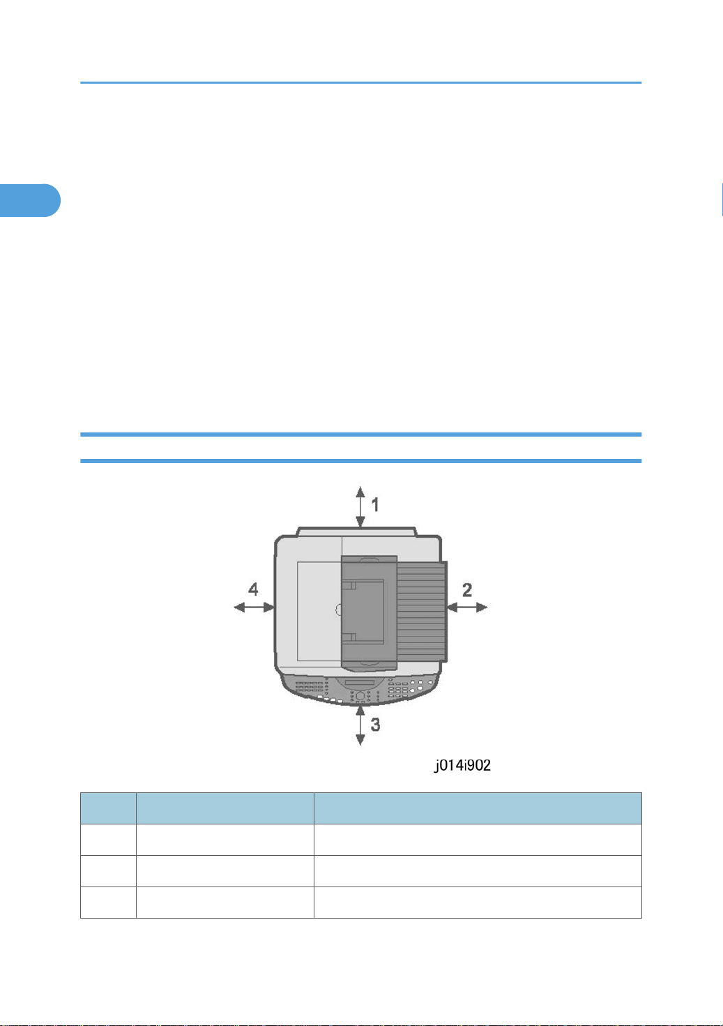
Minimum Space Requirements
No. Minimum Clearance Comments
1 120 mm (4.8 in.) Without Multi Bypass Tray
230 mm (9.1 in.) With Multi Bypass Tray
2 50 mm (2 in.) Applies to J012
26

No. Minimum Clearance Comments
1
75 mm (3 in.) Applies to J013/J014
3 190 mm (7.5 in.)
4 50 mm (2 in.)
Power Source
North America 100-120 V, 50-60 Hz
Europe 220-240V 50-60 Hz
Computer Hardware and Software
Here are some important notes about computer hardware and software.
Preparation
• Minimum requirements.
Computer PC/AT compatible with USB interface
OS
HDD Toscana-C1a (J012) 240 MB
• For Windows NT 4.0, IE 4.0 or later is required.
• Windows NT 4.0 does not support USB connection with this machine. Connect the machine through
a network connection.
• The following operating systems support USB connection: Windows 98, Windows Me, Windows
2000, Windows XP, Windows Server 2003.
• The following memory capacities are required for optimum performance. These are minimum
requirements. More memory is strongly recommended.
Operating System Minimum Memory Required
Windows 98, Windows Me, Windows 2000, Windows XP, Windows Server
2003, Windows NT 4.0 or later
Toscana-C1b (J013) 295 MB
Toscana-C1bN (J014) 300 MB
Windows 98 64 MB
27

1. Installation
1
Operating System Minimum Memory Required
Windows 2000 128 MB
Windows XP 128 MB
Windows Server 2003 256 MB
Windows NT 4.0 64 MB
• This machine does not support operation with Windows XP 64-Bit Edition or Windows Server 2003
64-Bit Edition.
28
Using the Operation Panel
1
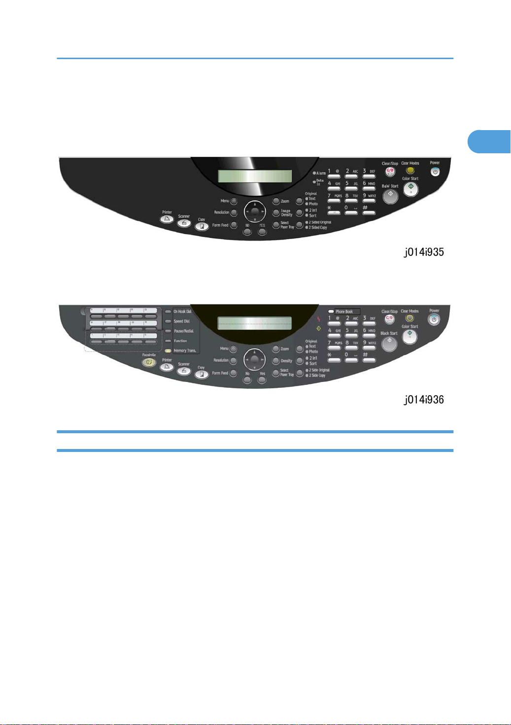
Using the Operation Panel
Here is a brief description of how to use the keys on the operation panel. The operation panel below is for
the J012. It has fewer keys because it does not support the fax function.
The operation panel below is common for the J013/J014 and has all the fax keys on the left because both
machines support the fax function.
Summary of Important Operation Panel Keys
For a more detailed summary about the operation panel keys, please refer to the User Guide. Only the
most important keys that may be required for servicing and maintenance are described below.
29
 Loading...