

Page 1
Page 2
TYREGUARD
TYRE GUARD
1
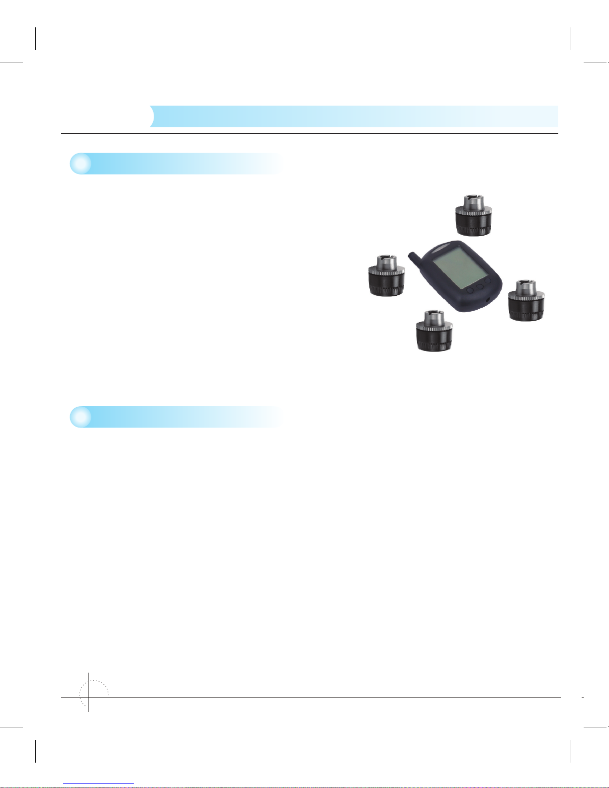
1 Introduction
Congratulations on purchasing the new
TYREGUARD 400 - TYRE PRESSURE MONITORING
SYSTEM (TPMS). This system is a safety system
for monitoring vehicle’s tyre air pressure and
temperature. It consists of external mounted tyre
pressure wireless sensors fitted to the vehicle’s
tyre valve and a hand-held monitor. The sensor will
monitor the tyre’s air pressure and temperature. The
sensor transmits the tyre pressure and temperature
information to the dash-mounted/hand-held monitor.
The monitor can be placed on the dashboard, on
the sun visor or mounted in any convenient place in the vehicle.
2 Function
The monitor’s function is to receive the temperature and pressure information transmitted
from a sensor fitted to each tyre and display this information on the screen in the specific
units of measurement of your choice.
The monitor will emit an alarm when a tyre pressure or temperature varies markedly (refer
pages 8-12) from the targeted tyre pressure and/or temperature. The system will detect
high or low air pressure as well as high temperature or rapid leakage from the tyres.
The monitor will flash the red LED icon and an alarm will sound to remind the operator
to check if the tyres are high or low in air pressure, leakage, high temperature or the
monitor’s battery is low, or there is a problem with a sensor. This advanced tyre monitoring
system offers these great features and benefits, is reliable, lightweight and compact.
SENSOR
MONITOR
Page 3
TYRE GUARD
TYREGUARD
2
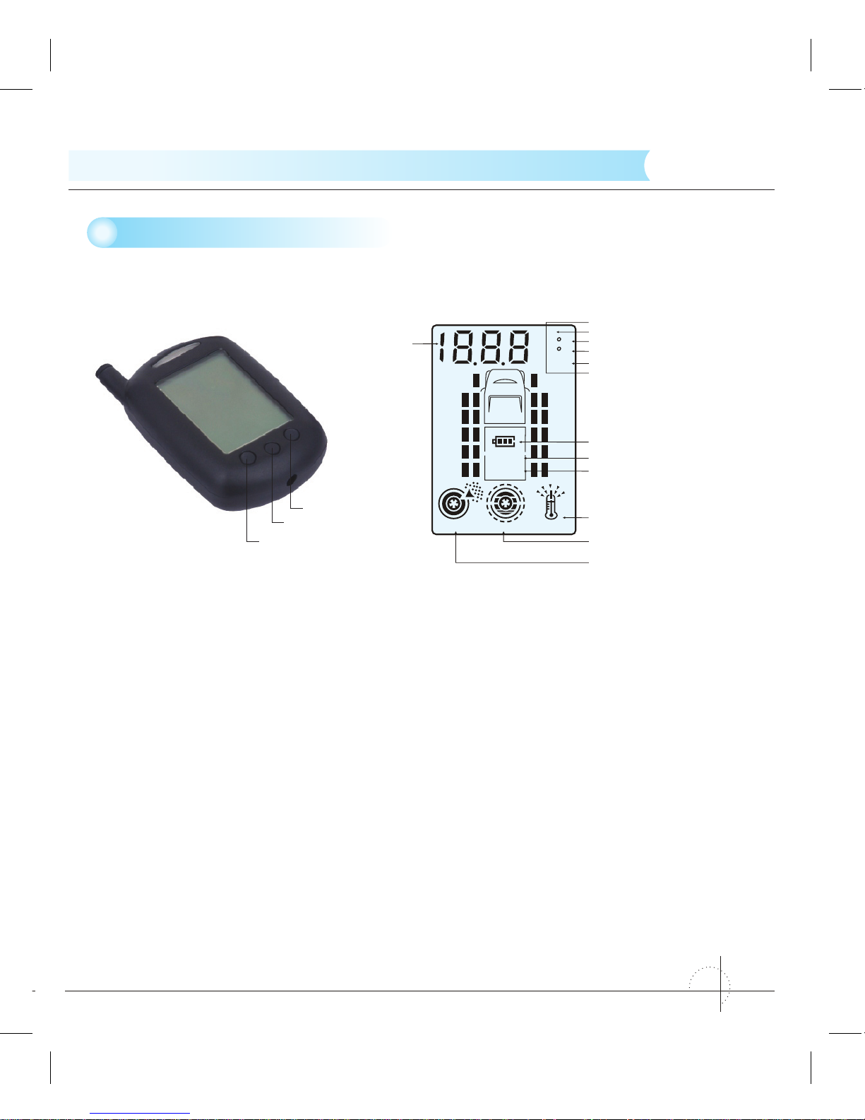
3 Installation & Operating Instructions
The following instructions show the identification of operating buttons of the monitor.
Units Conversion
Temperature Units Conversion
F=9C/5+32
Note: C = Celsius; F = Fahrenheit
Pressure Units Conversion
1 Bar=14.5 psi
1 Bar=100 kPa
1 Bar=1.02 kgf/cm
2
PSI
KPa
Bar
Kgf/cm
2
Pressure
sensor
monitor
TempLeaking
TEMPERATURE CONDITION icon
BATTERY CONDITION icon
Bar icon
KPa icon
PSI icon
Kgf/cm
2
icon
˚C icon
˚F icon
NUMERICAL
INDICATING
SECTION
MONITOR icon
SENSOR icon
PRESSURE CONDITION icon
LEAKAGE icon
C
F
Please ensure the monitor is fully charged and is in the tyre alignment mode before
installing the tyre sensors.
Before installing sensors and setting the monitor, make sure you have inflated the
vehicle’s tyres to your required pressures.
Note: It is recommended to set tyre pressures at those recommended by the manufacturer
listed in the vehicle’s handbook.
“→” button
“
→
” button
SET button
Page 4

TYREGUARD
TYRE GUARD
3
Tyre alignment mode
Hold down the “
→
” and “→” buttons simultaneously on the monitor for 5 seconds to enter
tyre alignment mode, and press either “
→
” or “→” button to select the specific tyre that
needs to be aligned.
Screw a sensor to the tyre valve stem and the current pressure will be displayed against
the corresponding flashing tyre icon on the screen. Once the tyre is aligned successfully
the green light appears on the monitor. The red LED light appears on the monitor if the
sensor hasn’t been aligned and “- - -” also appears on the monitor.
Note: If the sensor is to be removed from one valve and fitted to another valve, you must
delete the current setting on the monitor and realign this sensor to the new tyre. To delete
an aligned sensor from a tyre, hold down the SET button for 5 seconds.
When you exit the alignment mode, by again holding down the “
→
” and “→”, buttons
simultaneously on the monitor for 5 seconds to check the pressures and temperatures,
the monitor will indicate the data of the selected tyre. Click through to ensure all tyre
pressures and temperature details are in accordance with your requirements. After your
checks are completed, the backlight will go out and the monitor will indicate the tyre
pressure of the selected tyre.
The monitor may initially show abnormalities until you have set your required pressures
and units of measurement. These will be done in the Standard Pressure Setting and unit
selection setting below.
Page 5

TYRE GUARD
TYREGUARD
4
Installation of the Sensor and anti-theft device
The sensor of TYREGUARD 400 has an anti theft ring
to prevent the sensors being stolen. Firstly, place the
anti-theft ring over the valve stem, with one side of the
inner hexagon facing out, place the hexagon head
of the sensor into the inner hexagon and then screw
down the sensor; finally, place the inner hexagon
screws of the anti-theft device and tighten with the
key provided. Please refer to the right graphics A, B
and C when installing the rings.
It’s very simple to install the sensors. Screw a sensor
to each tyre valve stem as the picture shows.
Note:
1. Always install the sensor when the tyre is cold
2. Please check each tyre valve is not damaged.
3. Check to ensure there are no leaks and the sensors
are firmly secured to each tyre valve.
Installation of the Monitor
The monitor can be mounted using the pedestal or brackets supplied. The monitor can
be fixed to a suitable surface in the vehicle, sun visor, dashboard etc. It has a build-in
lithium battery or you may wish to use a power source from within the vehicle’s power
socket to charge or operate the monitor.
Page 6

TYREGUARD
TYRE GUARD
5
Standard Pressure Setting
Hold down the SET button of
the monitor for 5 seconds to
enter into the setting mode, as
the right graphic shows. Press
“
→
” or “→” button to set the
required pressure, and then
quickly press the SET button
to scroll through to the next the
tyre and repeat this sequence
to set the remaining tyres.
After you have completed setting all the tyre pressures, then set your preferred units of
temperature and pressure measurement, “kpa”, “Bar”, “PSI” and “kgf/cm2” for pressure units
and “F” and “C” for temperature, by pressing the “
→
” or “→” button. The corresponding
icon will flash when a certain tyre or unit measurement is chosen to be set.
Hold down SET button for 5 seconds to exit the Standard Pressure Setting mode.
Examination of the Tyre Condition
During the standby mode, press “
→
” or “→” button to check the air pressure and
temperature of the designated tyre. When you press the “
→
” button the monitor will scroll
through the current pressure and temperature of each tyre, as graphics A & B below
show. The indicating cycle is as follows:
» pressure of the front left tyre →
» temperature of the front left tyre →
» pressure of the front right tyre →
» temperature of the front right tyre →
» pressure of back left tyre →
» temperature of the back left tyre →
» pressure of back right tyre →
» temperature of the back right tyre → and so on.
When you press the “
→
” button the above indicating
cycle is reversed.
CDAB
Bar
C
Pressure
Temp
BarC
Pressure Temp
Bar
Pressure
Page 7

TYRE GUARD
TYREGUARD
6
The monitor indicates “- - -“when a specific sensor’s
alignment is lost from the monitor, as graphic C
shows. Refer to Tyre Alignment Mode on page 3
to realign sensor.
The monitor will indicate the “no S” signal whenever
a sensor is either out of range or may be faulty, as
graphic D shows.
Battery Capacity Indicator of the Monitor and
Sensor
When the monitor is low on power, the battery icon and “MONITOR”
icon on the screen flash, the buzzer gives a 10 second intermittent
alarm. The monitor then sounds every 30 seconds within 5 minutes
of total discharge.
When a tyre sensor has low power, the battery icon and “SENSOR”
icon together with the corresponding tyre icon flash on the screen and
a 10 second intermittent alarm will sound. If the power of any of the
sensors becomes too low, please replace the corresponding battery
immediately.
Charging the Monitor
The built-in lithium battery of the monitor is rechargeable. Please connect the 12/24V DC
charger into the port at base of the monitor, and
then insert the adapter plug into the port of the
vehicle’s 12/24V DC accessory port. The vehicle’s
battery power will charge the monitor when the power supply of the vehicle is turned on.
It takes approximately 6 hours to fully charge the monitor.
The battery icon flashes as shown in graphic A, B and C above.
The monitor will sound an alarm when fully charged. Graphic C will disappear after
1 second.
Note: Please keep the monitor in a cool environment when charging.
CDAB
ABC
monitor monitor monitor
monitor
sensor
Page 8

TYREGUARD
TYRE GUARD
7
Sensor battery replacement
Replace the corresponding sensor’s battery when
the monitor indicates a low battery. Unscrew the
plastic cap from the sensor, take out the battery
and replace with a new button cell battery, (CR
1632). Ensure the “+” terminal is touching the
upper bracket. Screw down the cover. Please
refer to the right graphic A, B and C
Note:
1. The battery model required for the sensors is
a CR1632 button battery.
2. The “+” and “-” pole of sensor battery must
be placed in the correct position with the “+”
terminal facing up; failure to do so may cause
the sensor to burn out.
3. In order to make sure that the battery is
replaced correctly, enter tyre alignment mode
and delete the alignment of the respective
sensor and realign it again.
Power up
Quickly press SET button to enter into the stand-by mode at the power off state.
Note: Once the monitor is turned on, the information from all tyres can take up to 4
minutes to be received in normal conditions. When the sensors are in an area of strong
interference or in very cold conditions, the monitor may not receive the signal. Pull out the
monitor’s antenna to increase the strength of the signal.
BATTERY
A
B
C
SENSOR SENSOR COPING
“+” POLE OF BATTERY
Page 9

TYRE GUARD
TYREGUARD
8
Power off
Hold down SET button for at least 8 seconds, and the monitor will automatically switch
off. Please note: the system will first enter into the setting mode 5 seconds after holding
down SET button, continue holding down the SET button for a further 3 seconds or more
to power off the monitor.
Note: Whether the monitor is turned on or off, the sensor is always in standby mode.
Standby Time
The monitor is installed with an intelligent 15 minutes suspension device. The monitor
turns into suspension status to save the power after the vehicles is switched off for more
than 15 minutes. Once the vehicle is started, the monitor automatically turns on and
connects to the vehicle’s sensors.
4 Warning Conditions
The TYREGUARD 400 possesses the two functions, monitoring tyre temperature and air
pressure conditions of the vehicle’s tyres.
Rapid Leakage
When the air pressure of a tyre drops more than 0.2 Bar (3psi) within
2 minutes, the monitor will give an alarm and the corresponding
icon will flash on the monitor’s screen to indicate which tyre has the
abnormal air pressure and its current air pressure. The air pressure
icon will flash along with the flashing red LED on the monitor, as the
right graphic shows.
Pressure
Leaking
Bar
Page 10

TYREGUARD
TYRE GUARD
9
Temp
C
Slow Leakage
When the air pressure of a tyre drops more than 0.2 Bar (3psi)
within 2~10 minutes, the monitor will give an alarm and the
corresponding icon will flash on the monitor’s screen to indicate
which tyre has the abnormal air pressure and its current air
pressure. The air pressure icon will flash along with the flashing
red LED on the monitor, as the right graphic shows.
Note: Whether there is a fast or slow leak, the sensor will send
a message to the monitor while driving or stationary.
High Temperature Warning: Level 1
When the temperature inside the tyre exceeds 75°C, the system
will give a class 1 high temperature alarm and the monitor will
indicate the position of the tyre with abnormal temperature and
its current temperature. Abnormal temperature is indicated by
the flashing red LED on the monitor and the temperature icon
flashing on the screen, as the right graphic shows.
High Temperature Warning: Level 2
When the temperature inside the tyre exceeds 85°C, the system
will give a class 2 high temperature alarm and the monitor will
indicate the position of the tyre with abnormal temperature and
its current temperature. Abnormal temperature is indicated by
the flashing red LED on the monitor and the temperature icon
flashing on the screen, as the right graphic shows.
Bar
Pressure
Leaking
Temp
C
Page 11

TYRE GUARD
TYREGUARD
10
Low Air Pressure Warning: Level 1
When the actual air pressure is equal to or falls below 85% of the
set pressure the system will give an alarm and the monitor will
indicate the position of the tyre with abnormal air pressure and
its current air pressure. The low air pressure is indicated by the
flashing red LED on the monitor and the pressure icon flashing
on the screen, as the right graphic shows.
Low Air Pressure Warning: Level 2
When the actual air pressure is equal to or falls below 75% of the
set pressure the system will give an alarm and the monitor will
indicate the position of the tyre with abnormal air pressure and
its current air pressure. The low air pressure is indicated by the
flashing red LED on the monitor and the pressure icon flashing
on the screen, as the right graphic shows.
Low Air Pressure Warning: Level 3
When the actual air pressure is equal to or falls below 50% of the
set pressure the system will give an alarm and the monitor will
indicate the position of the tyre with abnormal air pressure and
its current air pressure. The low air pressure is indicated by the
flashing red LED on the monitor and the pressure icon flashing
on the screen, as the right graphic shows.
Bar
Pressure
Bar
Pressure
Page 12

TYREGUARD
TYRE GUARD
11
High Air Pressure Warning
When the actual air pressure is equal to or greater than 120% of
the set pressure the system will give an alarm and the monitor
will indicate the position of the tyre with abnormal air pressure
and its current air pressure. The high air pressure is indicated
by the flashing red LED on the monitor and the pressure icon
flashing on the screen, as the right graphic shows.
Multi-Warning Indication
1. When one tyre has numerous abnormalities at once,
the monitor will indicate all the various abnormalities
as the graphic at right shows.
2. When there are abnormalities with two or more tyres
at the same time, the respective tyre icons with the
abnormalities will flash on the screen. Further, the
current tyre reading being displayed, its tyre icon
will flash more rapidly than the other icons, as the
right graphic shows.
Pressure
Leaking
Bar
Slow
Slow
Fast
Bar
Pressure
Bar
Pressure
Page 13

TYRE GUARD
TYREGUARD
12
Sensor Abnormality Indication
If the monitor can’t receive the signal from the sensors within 20
minutes in standby mode, the alarm system will sound for 15 seconds
along with the flashing LED on the monitor. The corresponding
icon of the abnormal sensor will also flash and indicate with
“no S” which indicates there is either a fault with the sensor, the
sensor is damaged or the sensor is out of range. The system will
alarm every 20 minutes if the monitor still can’t receive the signal
from the sensor, as the graphic at right shows.
Note: When the monitor is off or in standby mode, the monitor will
display “no S” instead of the detailed pressure and temperature
readings. The monitor will indicate the correct readings within 4 minutes of activation.
Explanation
The monitor will give out a continuous alarm for 15 seconds with the flashing red LED and
back lights for 5 minutes along with the corresponding faulty tyre icon flashing. Press the
“
→
” or “→” button to stop this alarm. Shortly after, the back light will automatically go off.
The system alarm will sound again after one hour to further remind the operator.
When a sensor is removed to inflate or deflate a tyre, this will cause the sensor to detect
rapid and/or slow leakage because the sensor has suddenly detected zero pressure.
The monitor will return to normal and the alarm will stop after the sensor is refitted within
approximately 10 minutes.
If you wish to add further sensors to the monitoring system, i.e. fitting sensors to an
additional caravan or trailer, etc. refer to procedure 3, Installation & Operating
Instructions.
Page 14

TYREGUARD
TYRE GUARD
13
5 Technical Specifications
Sensor
Working Temperature
-20°C -- 85°C
Working Humidity
0 -- 95%
Dimension
23 x 21 x 21mm
Weight
9g
Battery Voltage
3V DC (CR1632)
Battery Life
1 year
Standby Current
500nA
Working Current
6mA
Pressure Measure Range
0 Bar -- 10 Bar
Pressure Measure Precision
±0.3 Bar
Temperature Measure Range
-20°C -- 85°C
Temperature Measure Precision
±3°C
Signal Transmitting Frequency
433.92 MHz
Operating Distance
The monitor will detect a signal from each sensor up to 8.0
metres. Beyond this distance a Booster (Part No. 1020) must
be fitted. The booster will assist with the monitoring of tyres up
to 18.0 metres from the monitor.
Monitor
Working Voltage
3V DC
Working Temperature
-20°C -- 60°C
Working Humidity
0 -- 90%
Standby Current
0.1mA
Working Current
15 mA
Dimension
90 x 55 x 24mm
Signal Receiving Frequency
433.92 MHz
Color of Backlight
White
Page 15

TYRE GUARD
TYREGUARD
14
6 TYREGUARD Assembly
Description Quantity
Sensors Four (4)
Monitor One (1)
Bracket One (1)
12/24 V DC Cigarette Lighter Adapter One (1)
Sensor anti-theft security devices Four (4)
Hexagon Screw Four (4)
Hexagon Allen Key Two (2)
Guarantee Card One (1)
User Manual One (1) book
NOTE
1. This system can efficiently monitor the air pressure and temperature of the vehicle’s
tyres.
2. In order to avoid damage to this equipment, please do not attempt to disassemble
any assembly.
3. Your TYREGUARD 400 system has an automatic monitoring function, so there is no
need to press “
→
” or “→” to read the information.
4. Please contact Davies, Craig Pty Ltd.
T: +61 (0) 3 9369 1234
F: +61 (0) 3 9369 3456
E: info@daviescraig.com.au
or log on to our website www.daviescraig.com.au should you require further
information.
 Loading...