

Page 1

P/No:18924 – EWP Kit Customer Instructions. Page 1 of 12
77 Taras Avenue
P.O. Box 363
Altona North
Vic 3025 Australia
Phone: +61(0)3 9369 1234
Fax: +61(0)3 9369 3456
ELECTRIC WATER PUMP (EWP®) KIT
INSTALLATION INSTRUCTIONS
EWP80, EWP115, EWP130, & EWP150 Kits
PLEASE READ ALL THESE INSTRUCTIONS THOROUGHLY BEFORE YOU START WORK.
DON’T RUSH - ENSURE YOU HAVE FULL UNDERSTANDING OF THE WORK AHEAD BEFORE YOU
COMMENCE. ENSURE YOU HAVE ALL TOOLS AND COMPONENTS REQUIRED.
Congratulations on your purchase of the Davies, Craig EWP® Electric Water Pump Kit
which is designed to replace or complement the existing belt driven mechanical water
pump. In addition with a Davies, Craig Digital Controller your thermostat can be
replaced. The major benefits of an Electric Water Pump (EWP®) are, removal of the
parasitic power losses running a mechanical water pump at any speed, reduction of
engine warm-up time and elimination of heat soak by running the EWP® after a hot
engine shut down by operating the EWP® with the EWP/Fan Digital Controller, or one
of the Davies, Craig Thermatic® Switches. Your new EWP® has the advantage of
providing the best coolant flow rate independent of engine speed.
TABLE OF CONTENTS
EWP KIT CONTENTS .................................................................................................................................................... 2
SECTION 1: INSTALLING YOUR EWP
®
................................................................................................................. 3
SECTION 2: OPTIONS FOR PUMP CONTROL ...................................................................................................... 4
SECTION 3: DISABLE EXISTING MECHANICAL WATER PUMP .................................................................... 8
SECTION 4: BLEEDING THE EWP
®
........................................................................................................................ 9
SECTION 5: OPERATING YOUR EWP
®
ELECTRIC WATER PUMP ............................................................... 10
CAUTIONS ..................................................................................................................................................................... 11
Page 2
Page 2 of 12
EWP KIT CONTENTS
EWP130 (12V/24V)
EWP Components
Hardware Bag Components
Part #
Description
Qty.
Part #
Description
Qty.
8180 or
8181
EWP Pump Short (12V)
EWP Pump Short (24V)
1
N/A
Scotch Lock
1
N/A
Ring Terminal
1
8515
Wiring Harness
1 N/A
Self-Tapping Screw
1
18301
L Adaptor 35mm (Alloy)
1 N/A
Adaptor M5 Bolt
12
18302
Straight Adaptor 35mm (Alloy)
1 N/A
Relay
1
8509
O-Ring
2 18510
EWP Rubber Sleeve 3mm
2 18512
Hose Clamps
2
8909 /
8910
Hardware Bag
1
EWP150 (12V) - EWP115 Alloy (12V) - EWP115 Nylon
EWP Components
Hardware Bag Components
Part #
Description
Qty.
Part #
Description
Qty.
8160 or
8140 or
8125
EWP150 Pump Short
EWP115 Alloy Pump Short,
EWP115 Nylon Pump Short
1
N/A
Scotch Lock
1 N/A
Ring Terminal
1
N/A
Self-Tapping Screw
1
8515
Wiring Harness
1 N/A
Relay
1
18510
EWP Rubber Sleeve 3mm
2
18512
Hose Clamps
2
8526
EWP Hardware Bag
1
EWP80 Nylon (12V)
EWP Components
Hardware Bag Components
Part #
Description
Qty.
Part #
Description
Qty.
8105
EWP Pump Short
1 N/A
Scotch Lock
1
8515
Wiring Harness
1 N/A
Ring Terminal
1
8309
Elbow Adaptor 35mm (Nylon)
1 N/A
Self-Tapping Screw
1
8307
Straight Adaptor 35mm(Nylon)
1 N/A
Adaptor M5 Bolt
6
8509
O-Ring
2 N/A
Adaptor M5 Nut
6
18510
EWP Rubber Sleeve 3mm
2 N/A
M5 Cap Screw Long
6
18512
Hose Clamps
2 N/A
Relay
1
8908
EWP Hardware Bag
1
Optional Accessories
Part #
Description
Suitable for
No.
1025
Flanged Adaptor
All EWPs
1
1024
90 Degree Adaptor
EWP115 (Alloy
Only), EWP150
2
8700
EWP Mounting
Bracket
EWP115
EWP115
EWP130
3
8000
Digital Controller
All EWPs
4
1.
3.
2.
4.
Page 3
Page 3 of 12
SECTION 1: INSTALLING YOUR EWP®
1. Your EWP® Electric Water Pump is best fitted in the lower radiator hose which
connects the radiator to the existing mechanical water pump housing. In
conventional vehicle operating conditions, the hose will carry the weight of your
EWP® and insulate the EWP® from engine vibration. Check the area for available
space. Further radiator hose or adaptors may be required. Position the EWP® in
the lower hose so the inlet, in the centre of the pump is connected to the radiator
side and the outlet is connected to the engine’s mechanical water pump housing
or your EWP® Header Adaptor (not supplied). The EWP® should be positioned as
low as possible to maximise the gravity feed from the radiator and to avoid air
entering and remaining in the pump.
Alternatively, the EWP
®
may be fitted in the upper radiator hose. In this case,
coolant level is critical and bleeding of all air from the cooling system essential.
Follow instructions above for correct EWP
®
fitment ensuring the pump outlet is
connected to the hose going into the top of the radiator. The pump can be
installed in any orientation but to assist air bleeding try to mount the outlet
pointing upwards. (See Section 8 for bleeding instructions). Ensure your cooling
system is kept full of coolant.
2. If you have either an EWP130 or EWP80, assemble the provided EWP Straight and
L Adaptors to suit the configuration and space available. Ensure that the Straight
and L Adaptors have the O-Ring fit securely between them and the flange faces on
the EWP body. Six of the shorter Adaptor M5 Bolts (Part # 8507) should be used
to attach the Adaptor to the EWP outlet. The remainder M5 bolts (Part # 8507 for
EWP130) or (Part # 8514 for EWP80) can be used to attach the Adaptor to the
EWP Inlet.
If necessary, add the rubber sleeves to the inlet and outlet of the EWP® to suit
your particular hose diameter. If you require thicker sleeves, contact Davies, Craig
for supply free of charge.
3. Cut out the not required section of the radiator hose. Connect the pump inlet and
outlets to the appropriate hose ensuring hose clamps are very firmly tightened.
Page 4
Page 4 of 12
SECTION 2: OPTIONS FOR PUMP CONTROL
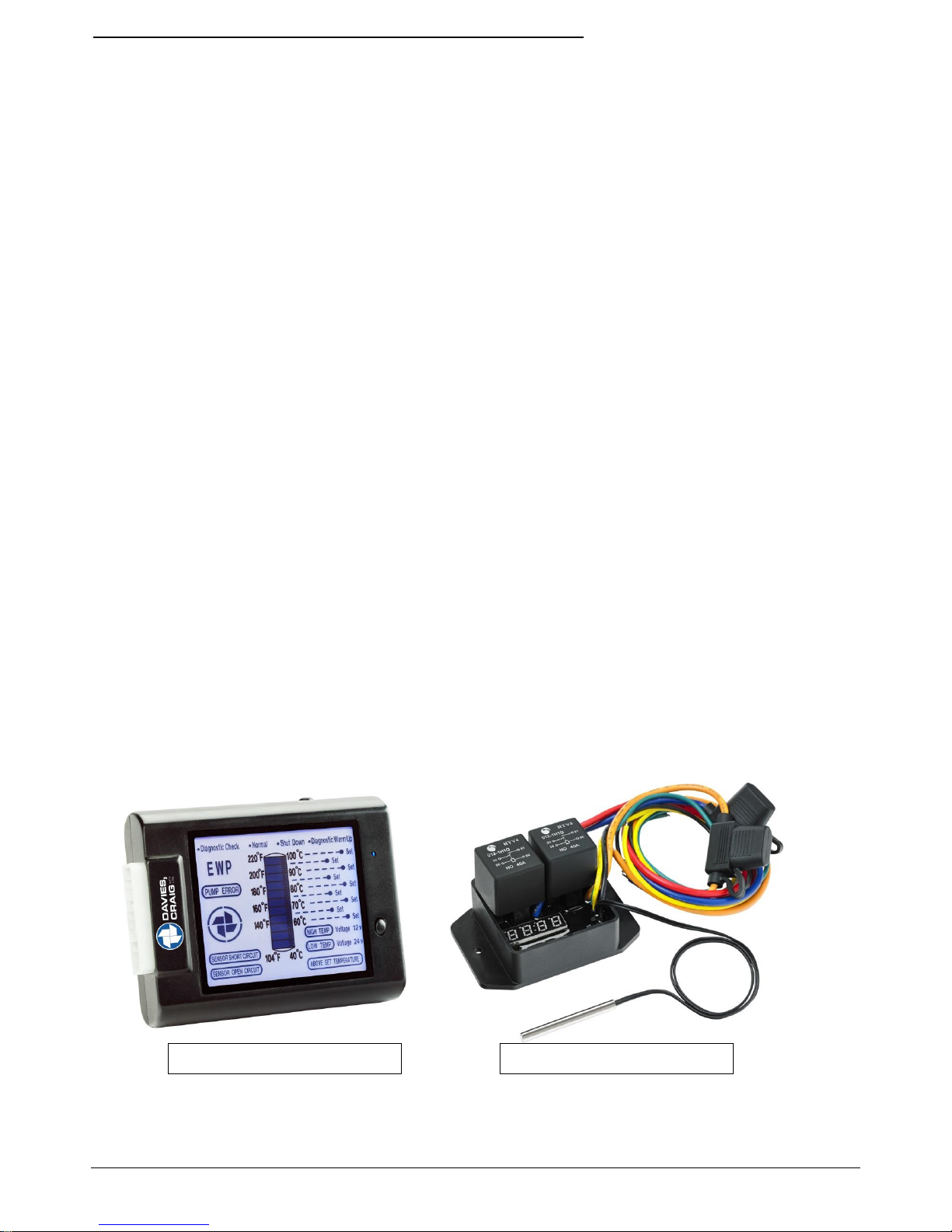
1. With EWP® Fan Digital Controller, Part #8000 or Part #8020:
We highly recommend the use of the EWP® & Fan Digital Controller for maximum
cooling efficiency. The EWP® & Fan Controller will vary the EWP® speed in response
to the coolant temperature. You set the temperature desired for maximum power
or fuel efficiency. The Digital Controller has an in built function that allows the
EWP® to run on after hot engine shutdown to eliminate heat soak. We further
recommend the removal of the engine’s thermostat and disabling of mechanical
water pump. The pump belt may need to be modified or the pump pulley left as an
idler. The vehicle’s heater may take a little longer to warm up and to improve the
heating, we recommend the fitment of an Electric Booster Pump (EBP) to the
heater line if necessary.
2. With Davies, Craig Thermatic® Switches, Part #0401 or Part #0444:
Combine the EWP® with either of the approved Davies, Craig thermal switches
listed here when the EWP® is used as a booster pump to assist the existing
mechanical water pump cool an overheating engine.
Connect the thermal switch directly to the battery and your EWP® will run on to
eliminate heat soak. You may leave the thermostat in place, but ensure the EWP®
operates only when the thermostat is fully open.
3. Continuous running:
Wire the EWP® direct to the ignition for maximum cooling (race vehicles, very hot
climates). This option requires the removal of the engine thermostat and the
mechanical pump impeller or pump belt. This option may also be used for road cars
with the thermostat in place with a small hole (suggest 5mm), allowing a small
amount of flow to circulate even when the thermostat is closed.
WARNING: When using the Electric Water Pump (EWP®) on vehicles using LPG, it
is recommended that an EBP be fitted to circulate coolant through the LPG
converter.
Part #8000 – LCD Controller
Part #0444 – Thermatic Switch
Page 5

Page 5 of 12
OPTION 1: INSTALLING EWP® & FAN DIGITAL CONTROLLER
Part #8000 or Part #8020
NOTE: Wiring from EWP® kit will not be required however retain for hard
wiring the EWP® during bleeding.
1. The Digital Controller must be fitted inside the passenger compartment.
2. Connect the wiring harness to the Digital Controller and mount the Controller in an
appropriate position --- avoid mounting the controller where it may be
exposed to direct sunlight.
3. An additional screw is provided for mounting Digital Controller fuse holder where
necessary.
4. Mount ‘Remote Test Light’ in a location, which will be visible. The ‘Test Light’ may
be fitted by inserting it through a 4.6mm hole drilled in a plastic area of the
interior/dashboard or simply with adhesive tape.
5. For installation of the sensor in the position of the thermostat refer to the Digital
Controller instruction booklet.
6. Bleed the EWP
®
. Refer to SECTION 4: BLEEDING THE EWP
®
(Page 9). After
bleeding the EWP® continue with the installation process.
Part #8020 Above
Part #8000
Page 6

Page 6 of 12
1. BLUE CONNECTOR
2
. SELF TAPPER
3
. SCTOCHLOCK
4
. RING TERMINAL
5. FUSE HOLDER & FUSE
3
THERMAL SWITCH
IGNITION
RED
YELLOW
BLACK
ORANGE
BATTER
+VE
4
FUS
RED
FUS5 5
EARTH
PUMP
RELAY
BLACK
BLUE
GREEN
2
86
30
87
85 1 1
1
OPTION 2: USING THE EWP® AS A BOOSTER PUMP
Part #0401 or Part #0444
NOTE: This option when combined with a Davies, Craig Thermatic® Switch,
Part #0401 or Part #0444, will turn the EWP® on at the temperature you set,
to give additional flow to an overheating cooling system.
INSTALLING THERMAL SWITCH (Part #0401 OR #0444)
1. Install the Thermo Switch (Part #0401 or Part #0444) - Refer Wiring Diagrams
(Figure 1 and Figure 2) below.
2. For detailed instructions on installing switches, please refer to 0401 & 0444
instruction sheets.
3. Bleed the EWP
®
. Refer to SECTION 4: BLEEDING THE EWP® (Page 9). After
bleeding the EWP® continue on with the next stage.
WARNING: ENSURE IGNITION SOURCE IS NOT CONNECTED TO THE ENGINE MANAGEMENT SYSTEM
2
Figure 1: Wiring Diagram: EWP® With Thermal Switch - Part #0401
Figure 2: Wiring Diagram: EWP® with Thermal Switch - Part #0444
THERMAL SWITCH
BATTERY
FUSE
EARTH
PUMP MOTOR
RELAY & LOOM
FROM PUMP
PACKAGING
+
_
BLACK
BLUE
RED
GREEN
BLUE
Page 7

Page 7 of 12
OPTION 3: CONTINUOUS RUNNING
(Recommended for race vehicles, very hot climate & cars running on LPG.)
Continuous EWP® operation may be required for some road or race engine
applications, in some very hot climatic conditions and engines fitted with liquid
petroleum/butane gas (LPG) conversion.
This option will provide maximum flow from your EWP® under all operating conditions
without a Digital Controller or a Thermatic Switch fitted. Should you choose this
method you should retain the engine thermostat and drill one or two holes (suggest
5mm) in the plate to allow some coolant flow when the thermostat is closed.
Figure 3: Wiring Diagram: EWP® Continuous Running
BATTERY
+
_
+VE IGNITION
SOURCE
FUSE
EARTH
PUMP MOTOR
RELAY & LOOM
FROM PUMP
PACKAGING
BLACK
BLUE
RED
GREEN
Page 8

Page 8 of 12
Crank Pulley
Water Pump
Pulley
Water Pump
Pulley
Crank Pulley
Alternator
Pulley
Alternator
Pulley
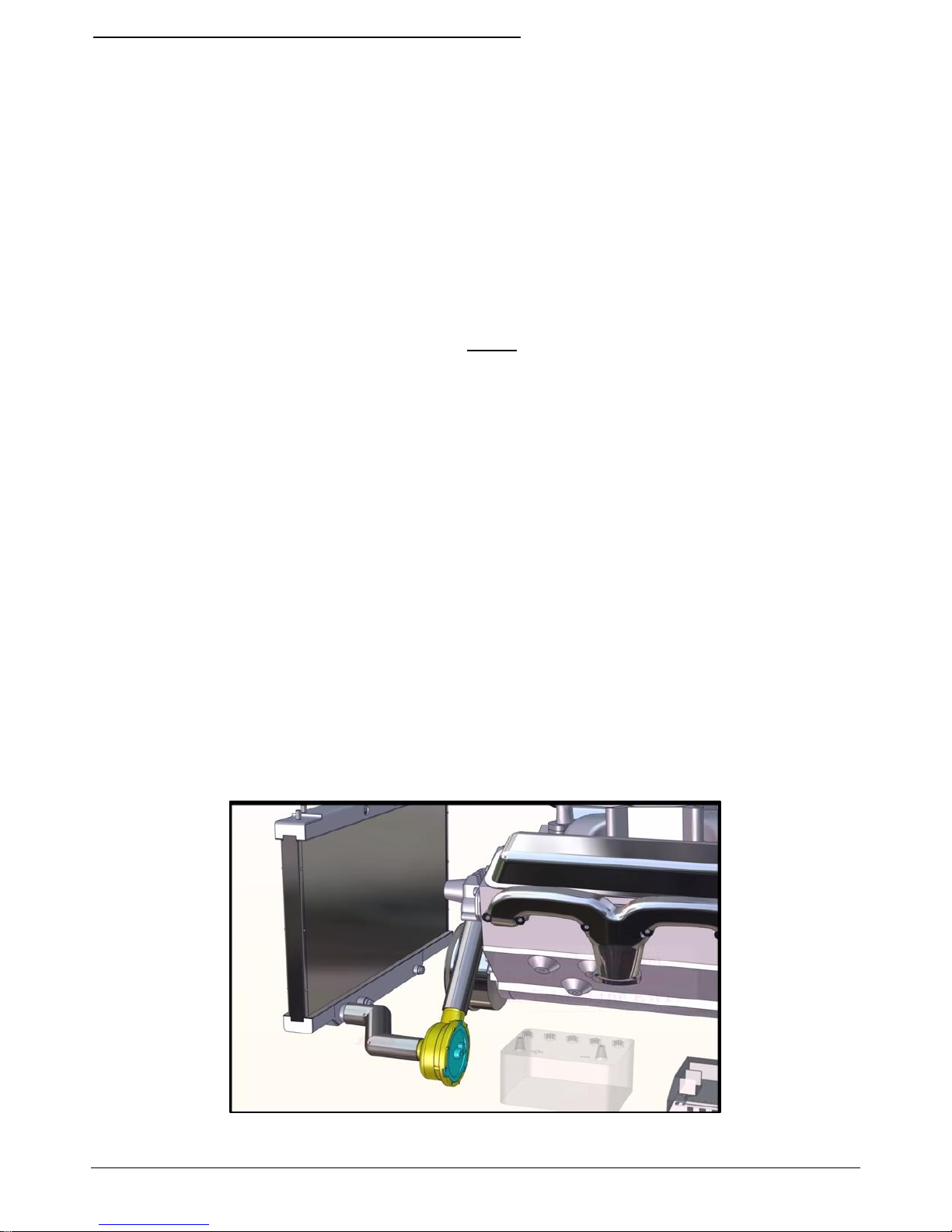
SECTION 3: DISABLE EXISTING MECHANICAL WATER PUMP
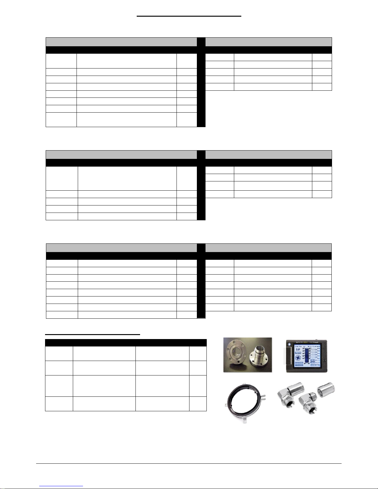
Davies Craig has tailor made EWP Header-Adaptor Kits – visit the website for
details, see image below (Part#8630).
1. You may choose to by-pass the belt-driven water pump pulley by installing a
shorter belt. This option may not be possible if the crank pulley drives a beltdriven power steering and fan or unless you replace the mechanical fan with a
Davies, Craig Thermatic® Fan. For example see Figure 4 below:
2. Remove the thermostat from the thermostat housing.
3. Re-fit the thermostat housing ensuring that there is no damage to the
thermostat-housing gasket.
OR
1. Remove the existing belt-driven water pump housing.
2. Remove the water pump impeller from the pump shaft. (NOTE: You may
need to drill holes through the impeller close to the drive shaft.)
Alternatively, remove vanes from impeller. Mechanical water pumps differ
from engine to engine and you need to take appropriate action that suits
the specific water pump to disable the pump.
3. Re-fit the water pump housing without the impeller ensuring that there is
no damage to the water pump gasket and the pump seal is still retained.
Re-fit the water pump belt and tighten to manufacturer’s specifications.
BEFORE
AFTER
Figure 4: Belt Orientation Diagram
Part #8630 - EWP Header-Adaptor Kit (Ford Big Block)
Page 9

Page 9 of 12
SECTION 4: BLEEDING THE EWP
®
For the EWP®80 ensure it is orientated correctly as shown below before
continuing.
NOTE: This orientation is a temporary requirement for the purpose of bleeding
the pump and ensuring there is no air entrapped within the seal housing of the
pump. The pump can be set-up in another orientation upon completion of the
bleeding procedure.
FOR ALL EWPS:
1. Fill the engine cooling system with appropriate coolant.
2. Turn heater on full.
3. With the radiator cap off, hardwire the EWP
®
directly to the vehicle’s battery
or a 12v power source. Air trapped in the cooling system will exit at the top
of the radiator.
4. Turn on engine and idle.
5. Top up the radiator with coolant with the EWP
®
running until all air is
eliminated. Waterless coolants increase the load on an EWP and may reduce
pump life.
6. Turn off engine.
7. Replace the radiator cap and reconnect the EWP
®
to the wiring system
supplied.
AIR POCKET
Figure 5: EWP80 Pump Orientation Diagram
INLET
Wrong Pump Orientation
Correct Pump Orientation
INLET
Page 10

Page 10 of 12
SECTION 5: OPERATING YOUR EWP® ELECTRIC WATER PUMP
Start engine, confirm no leaks at radiator hoses and re-torque radiator hose
clamps if required. Monitor the engine temperature, which should take longer
than usual to reach steady state. If the ignition is left on (or if a turbo timer is
connected) after a hot shut down, the pump will continue to run and prevent
engine heat soak. Re-tighten the hose clamps after a few hours running at
temperature and again after 20 hours running. Check for leaks. NB: The
heater circuit may take longer than normal to warm up.
SECTION 6: EWP INSTALLATION RECOMMENDATIONS
To ensure maximum life and optimum performance from your new EWP,
Davies, Craig recommends:
Storage - If a EWP
is installed in your vehicle’s engine cooling system,
stored and/or not started or driven for more than 3 months, e.g. a
show/static display or race car, it’s strongly recommended the EWP® is
operated for approximately 5 mins constant running every month. This will
minimise the build-up of any sediment in the EWP and also lubricate all
parts within the pump.
Heater - For improved heater performance on vehicles which have the
heater inlet (return) and outlet ports in the mechanical pump housing
(referred to in “Warnings”), Davies, Craig suggests the fitment of the EBP.
This unit fits into the heater hose and boosts coolant flow through the
heater circuit and/or cylinder heads. Check out website
www.daviescraig.com.au
LPG (Liquid Petroleum Gas or Butane) vehicles require constant flow
through the LPG converter and if the EWP is used in conjunction with the
EWP®/Fan Digital Controller, we recommend the installation of an EBP® to
overcome the converter body freezing at start-up. As a preventative
measure, we strongly recommended you flush out your engine’s cooling
system every 6 months or 10,000kms to help remove any build up of
sediment.
Page 11

Page 11 of 12
CAUTIONS
Do not operate your EWP
®
dry as seal damage may occur and your
warranty may be jeopardised.
Use of the EWP
®
after removing the pump impeller or deleting the
mechanical pump pulley from the belt system will increase maximum engine
speed. Running an engine at higher than normal speeds may affect other
engine components.
Engine temperature must be monitored closely at all times more especially
after installation and until your EWP® operational procedures have been
confirmed.
The EWP
®
can handle most rust particles, shale, and sludge found in cooling
systems but large rust particles should be flushed from the radiator before
the EWP® is installed.
Some engines may require special bleeding procedures to remove all air
from their cooling system. The EWP® must be completely full of coolant at
all times to achieve the life expectations of your EWP® and to ensure your
warranty is not jeopardised.
Do not use the vehicle’s engine management system or wiring connected to
the vehicle’s engine management system (ECU) as an ignition source as it
may cause failure of the management system and/or the electrical system.
The ignition source for your EWP
®
and EWP®/Fan Digital Controller Combo Kit
must be a steady positive supply of 12-14V or 24-27V DC.
Vehicles with both heater circuit inlet (return) and outlet ports in the
mechanical pump housing will suffer reduced heater performance unless the
heater returns position is relocated.
The engine cooling system must use coolant as specified by the vehicle’s
manufacturer.
The EWP
®
is a ‘circulation’ pump ideal for most ‘closed circuit’ pressurised
automotive cooling systems.
The EWP
®
is not a ‘self-priming’ water pump and therefore will not produce
its full flow without a positive ‘head’ in an ‘open’ system.
The EWP
®
impeller tip clearance has been designed to achieve maximum
efficiency and is therefore very close to the housing. When new and bedding
in, the impellor may touch the internal wall of the EWP® housing causing a
slight noise. This sound will cease within a very short time after the impeller
has bed-in.
Waterless coolants increase the load on an EWP and may reduce pump life.
These installation instructions will suit most vehicles but there are
circumstances surrounding some engine designs, environments, and
the nature of motoring involved, which may require other installation
arrangements not outlined here. Frequently Asked Questions are
listed on our website www.daviescraig.com.au Davies Craig Pty Ltd
appreciates customer feedback. Emails can be directed to
info@daviescraig.com.au or telephone +61 (0) 3 9369 1234.
Page 12

Page 12 of 12
WARRANTY
We warranty that for a period of two years or 2000 hours
continuous running (whichever is the lesser) from the date of
purchase, we shall carry out, free of cost, any repairs that are
reasonably necessary to correct any fault in the operation of your
Electric Water Pump provided that such a fault is directly
attributable to a defect in the workmanship or materials used in the
manufacture of the part(s) and is not due to installation other than
described in these instructions. Labour and consequential costs are
excluded.
DAVIES, CRAIG PTY. LTD.
REGISTER YOUR WARRANTY AT:
www.daviescraig.com.au
 Loading...