

Page 1
Page 1 of 8
EBP® INSTALLATION INSTRUCTIONS
DAVIES, CRAIG EBP® (ELECTRIC BOOSTER PUMP) AND OPTIONS FOR PUMP CONTROL
Congratulations on your purchase of the Davies, Craig EBP®. The EBP® is designed to compliment your
existing Davies, Craig EWP® (Electric Water Pump), or belt-driven mechanical water pump, or improve your
heater system or engine block circulation. The EBP® can continually circulate water around the engine head,
block and by-pass. It has a high flow capacity and has the advantage of running at a speed independent of the
engine speed. The EBP® can also be set to continue running with a timer (not supplied) after engine shut down
to prevent damaging heat rise.
PLEASE READ THESE INSTRUCTIONS IN THEIR ENTIRETY BEFORE YOU START WORK.
EBP® KIT CONTENTS:
Item No. Part
No.
Description Qty
1. 9012
EBP®
1
2. 9020
EBP® Adaptors
2
3. 9510 Adaptor Hose 2
4. 9511 Hose Clamps 4
5. 9516 Wiring Harness 1
Not
Shown
9901
Installation
Instructions
1
______________________________________________________________________
EBP® APPLICATION OPTIONS
The EBP® has been designed for a number of applications, these being:
1. Circulation Pump for LPG Vehicles – The EBP® improves water circulation through the engine block to
prevent LPG injector from icing up. Other advantages include a more constant engine temperature and
better engine cooling.
2. Heater Booster Pump – The EBP® increases heater performance during normal vehicle operation and
enables continued heater usage when engine is off (but IGNITION is ON).
77 Taras Avenue
P.O. Box 363
Altona North, Vic 3025 Australia
Phone: +61(0)3 9369 1234
Fax: +61(0)3 9369 3456
E-mail : d cfans@da vies craig. com .a u
Web: www.daviescraig.com.au
A.B.N. 71 004 918 825 A.C.N. 004 918 825
MELBOURNE AUSTRALIA
PTY.
LTD.DAVIES
,
CRAIG
ISO 9001
Lic No 4528
Standards
Australia
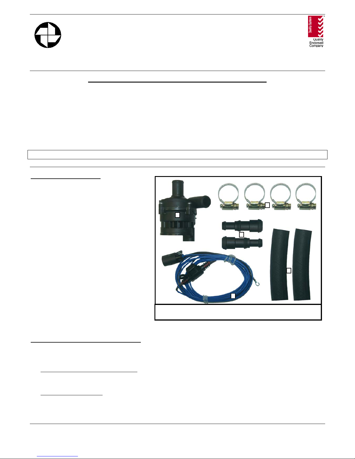
Figure 1: EBP and hardware components.
1
4
2
3
5
Page 2
Page 2 of 8
3. Water Pump for Liquid Cooled Motorcycle Engines - The EBP® provides liquid circulation independent of
the engine speed to provide cooling at all levels. It may be used with the EWP® Digital Controller to replace
the existing water pump or used with an override switch to compliment the existing system.
4. Multi-Purpose Pump – The EBP® may be used in a number of different applications where flow is required,
such as irrigation, camping, solar pumps, go-karts or marine operations.
INSTALLING THE EBP
®
The installation procedure is similar for each vehicle application: the pump is to be installed within the existing
hoses. However each application has a different method of use and/or control. These specific differences are
described in each appropriate application.
1. The EBP® is to be installed in the engine heater hose connecting the thermostat to the back of the engine
block. Check the area for available space and shape of the heater hose. The section of the heater hose
connected to the front of the block must be connected to the inlet of the EBP® and the section of heater hose
connected to the back of the engine block must be connected to the outlet of the EBP®. “Inlet” and “outlet”
of pump may be determined by arrows on the pump or refer to Figure 2 below. The pump inlets and outlets
are connected using the hose-clamps provided. Tighten the hose-clamps after a few hours running at
temperature and again after 20hrs running.
2. If the existing heater hose diameter does not fit the inlet and outlet of the EBP®, the plastic adaptors (Item
No: 2) and adaptor hose (Item No: 3), may be used to configure a diameter that best suits your hose. The
adaptor is connected to the EBP® by clamping the adaptor hose to the appropriate inlet or outlet of the pump
and the other end to the largest diameter step on the adaptor. Each adaptor has 2 extra diameters to suit hose
diameters from 12mm to 19mm. It is suggested that if the second size step is used on the adaptor, the first
step should be sawn off to maximise coolant flow. This may be done with a hacksaw or similar device.
3. Once the EBP® is installed within the hose, the wiring harness (Item 5) is to be attached to the pump. The
wiring harness can be connected to the pump in only one configuration - the release tab on the wiring
harness connector must align with the tab-lock of the connector on pump housing.
4. The EBP® is then to be wired up as described in each appropriate application.
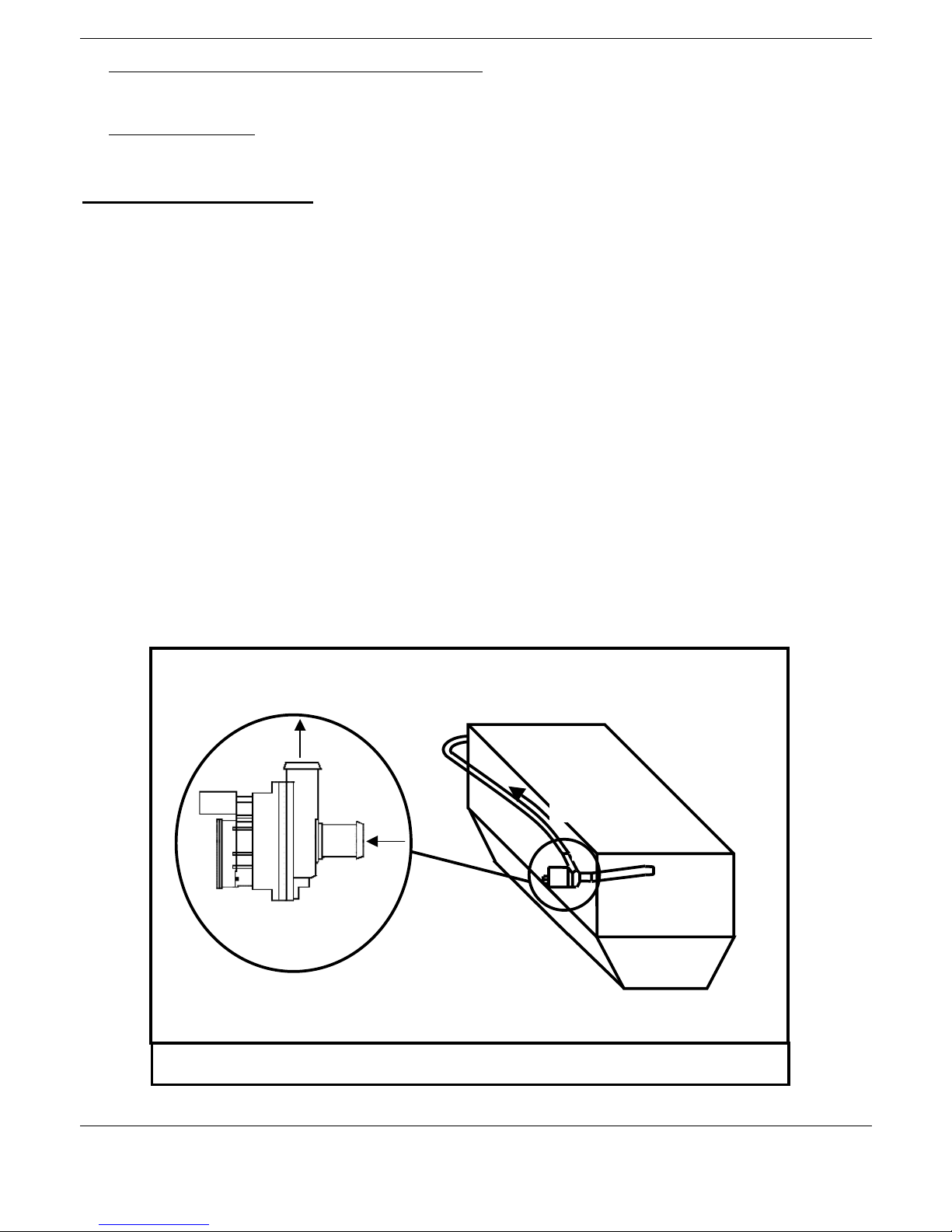
Figure 2: Schematic of Engine and EBP
®
Installation Position
Note: The position shown is for reference purposes only - EBP
®
can be positioned anywhere along hose.
Flow direction
for the EBP
Water Flow
Direction
Front of Engine
Rear of Engine
IN
OUT
Page 3
Page 3 of 8
APPLICATION 1: CIRCULATION PUMP FOR LPG VEHICLES
The EBP® improves water circulation through the engine block to improve LPG converter operation. Therefore,
it is necessary for the EBP® to be functional all times the engine is running; hence the pump is wired directly to
ignition. Other advantages include a more constant engine temperature and better engine cooling when set to
continue running after engine shut down.
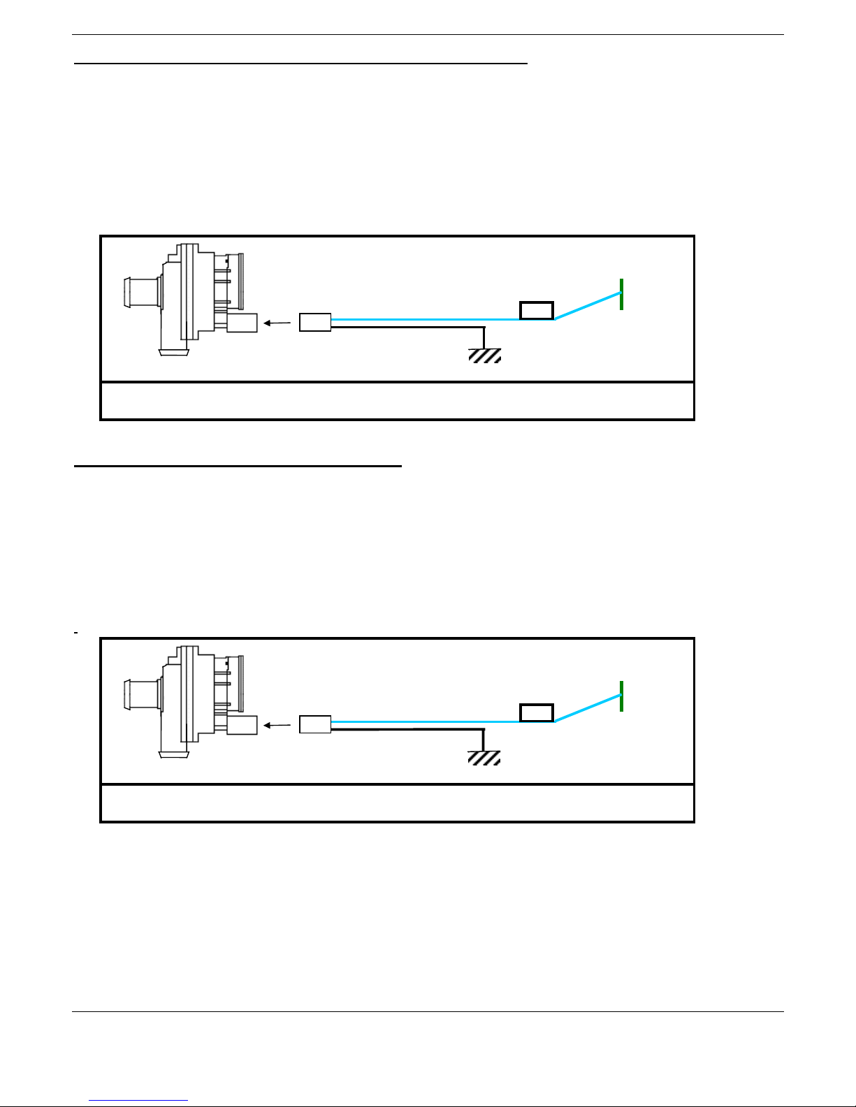
The EBP® is wired as shown below. Note: The pump is excited by a direct ignition source allowing operation
at all times the ignition is on.
APPLICATION 2: HEATER BOOSTER PUMP
The EBP® used in this application increases heater performance during normal vehicle operation and provides
continued heater usage when engine is off (but IGNITION is ON). The pump is excited by a direct heater
source, meaning that the EBP® is activated only when the heater is in use. The EBP® will not restrict flow in
the circuit when it is not in use.
The EBP® is wired as shown below. Note: The pump is excited by a direct heater source allowing operation
only when the heater is on. The heater fan is a recommended power source.
+VE IGNITION
SOURCE
FUSE
HOLDER
Figure 3: Wiring diagram for “CONTINUOUS EBP
®
RUNNING”.
Earth
+VE HEATER
SOURCE
FUSE
HOLDER
Figure 4: Wiring diagram for “EBP
®
OPERATION WITH HEATER SYSTEM”.
Earth
Page 4

Page 4 of 8
APPLICATION 3: MOTORCYCLE WATERPUMP
Two options are available for the EBP® in liquid cooled motorcycle engines:
1. With override switch to operate EBP® when extra cooling is required.
2. With a thermal switch to operate automatically at a set engine temperature.
MOTORCYCLE EBP® INSTALLATION
The installation procedure is similar for each motorcycle option: the pump is to be installed within the existing
cooling system hose. However each option has a different method of use and/or control, these specific
differences are described in each appropriate option.
1. The EBP® is to be installed in the bottom cooling system hose connecting the radiator to the engine block.
Check the area for available space and shape of the cooling hose. The section of the cooling hose connected
to the radiator must be connected to the inlet of the EBP® and the section of cooling hose connected to the
engine block must be connected to the outlet of the EBP
®
. “Inlet” and “outlet” of pump may be determined
by arrows on the pump or refer to Figure 2 below. The pump inlets and outlets are connected using the
hose-clamps provided. Tighten the hose-clamps after a few hours running at temperature and again after
20hrs running.
2. If the existing cooling hose diameter does not fit the inlet and outlet of the EBP®, the plastic adaptors (Item
No: 2) and adaptor hose (Item No: 3), may be used to configure a diameter that best suits your hose. The
adaptor is connected to the EBP® by clamping the adaptor hose to the appropriate inlet or outlet of the pump
and the other end to the largest diameter step on the adaptor. Each adaptor has 2 extra diameters to suit hose
diameters from 12mm to 19mm. It is suggested that if the second size step is used on the adaptor, the first
step should be sawn off to maximise coolant flow. This may be done with a hacksaw or similar device.
3. Once the EBP® is installed within the hose, the wiring harness (Item 5) is to be attached to the pump. The
wiring harness can be connected to the pump in only one configuration - the release tab on the wiring
harness connector must align with the tab-lock of the connector on pump housing.
4. The EBP® is then to be wired up as described in each appropriate application.
Location of EB P
Installation
Water
Pump
Cylinder
Cylinder Head
Radiator Fan Switch
Water Thermo Switch
Thermostat
Radiator Cap
To Coolant Reservoir Tank
Radiator
Figure 5: The Motor Cycle Liquid Cooling System.
Page 5

Page 5 of 8
OPTION 1: EBP® WITH OVERRIDE SWITCH
The EBP® may be used to compliment the existing cooling system and only be operational when additional
cooling is necessary.
1. As described above, the EBP® is to be installed in the cooling system hose between the radiator and the
existing water pump. The EBP® itself will not restrict flow in the circuit.
2. The EBP® may be wired with an override switch (not supplied in EBP® kit) as outlined in the wiring
diagram below. With this option the switch would be located at an accessible position on the instrument
panel.
3. Before the engine overheats close the switch to activate the pump. This in turn will increase the flow within
the cooling system and improve the cooling.
4. If the ignition is left on or with the introduction of a timer switch (not supplied) the EBP® can be set to
continue running after engine shut down to prevent damaging heat rise.
WIRING DIAGRAM: EBP® WITH OVERRRIDE SWITCH
OPTION 2: EBP® WITH THERMAL SWITCH
This option when combined with a Davies, Craig Thermal Switch (P/No: 0401 or 0402) will turn EBP® on at
the temperature you set to boost cooling. The pump will turn off when engine temperature has reduced by 4°C.
The EBP® is to be installed in the cooling system hose as described above between the radiator and the existing
water pump. The EBP® itself will not restrict flow in the circuit.
INSTALLING THERMAL SWITCH
1. When the engine is cold remove the top radiator hose at the radiator end. (Refer Diagram next page).
Mount the thermal switch to the bracket with the two small screws provided. Mount the bracket onto a
panel near the radiator so that the stainless steel bulb will easily reach into the top radiator hose. Ensure
that adjustment shaft is accessible. Fix the bracket in place with the two large self-tapping screws provided.
2. Lay the rubber seal along the radiator ferrule and place a section of the stainless steel capillary of the
Thermal Switch down the groove in the rubber seal. Keep the capillary loosely coiled and avoid sharp
bends. Do not pass the bulb further down the hose than is necessary as the constant movement of the engine
in relation to the radiator may cause fatigue of the capillary. The seal and tube may be held in place with
insulation tape.
3. Fit the hose and clamp so that the clamp is over the centre of the rubber seal and the clamp screw is in the
opposite side of the tube to the capillary and seal. A good silastic type sealant may be used if there is a
persistent leak
+VE HEATER
SOURCE
FUSE
HOLDER
Figure 6: Wiring diagram for “EBP
®
OPERATION WITH OVERRIDE SWITCH”.
SWITCH
Earth
Page 6

Page 6 of 8
4. Connect the pump wiring harness to the pump. Cut the blue wire before the fuse and crimp the spade
terminals (from Thermal Switch packaging) to each end. Connect spade terminals to each pin of thermal
switch. The connection order does not matter since both pins have the same polarity. The blue wire
provided with the thermal switch can also be used to increase length of blue wire form EBP®, otherwise this
can be discarded.
RUNNING THE EBP®
Run the engine and monitor the engine temperature, adjusting the thermal switch dial to turn the EBP® on at the
temperature desired. With the thermal switch connected directly to the battery, after a hot shut down, the pump
will continue to run and stop engine heat soak. Generally, running the engine slightly colder will increase the
power and running the engine slightly hotter will improve the fuel efficiency.
Tighten hose clamps after a few hours running at temperature and again after 20 hours running. Check for
leaks.
The EBP® used in conjunction with the EWP Digital Controller (P/No: 8020) may replace your existing
mechanical motorcycle water pump in certain situations if the existing motorcycle flow is 15 L/min or less.
Refer to EWP® Digital Controller instructions for detailed installation procedures.
Warning: Motorcycles may require special bleeding procedures (not described here) to remove air from the
cooling system. The EBP® must be completely flooded with coolant at all times to achieve the life specification
of the EBP
®
and to preserve warranty.
40ºC
100ºC
RADIATOR
TOP TANK
RUBBER SEAL
Figure 7: Schematic of Thermal Switch Installation
BATTE
R
Y
FUSE
HOLDER
Figure 8: Wiring diagram for “EBP
®
WITH THERMAL SWITCH”.
40ºC
100ºC
THERMALSWITCH
Earth
Page 7

Page 7 of 8
APPLICATION 4: MULTI-PURPOSE PUMP
The unique and robust design of the EBP® allows the pump to be used in a number of different applications as
to those described above. The EBP® is a centrifugal pump with an impeller driven by an electronically
commutated motor. This totally removes the problem of brush wear encountered on conventional motors with
their mechanical commutation systems. The design ensures a hermetic seal between the pump and the
electronic motor without the need for a shaft seal. Through the elimination of the mechanical commutator the
durability of the pump is only practically limited by the mechanical life of the rotor bearings. In addition the
noise emissions are reduced by the small amount of moving parts. The pump has an axially orientated inlet and
perpendicular outlet.
The EBP® in fact may be used in all situations that require a water flow-rate of up to 15L/min and where a
positive-head is available. Such applications may include:
♦ Go-Kart Water Pump – The EBP® may replace an existing non-pumped thermosiphon circulation system or
compliment the existing system. This is on the condition the system requires 15 L/min or less flow rate.
♦ Camping/Caravan/Recreation- the EBP® could be used in a variety of arrangements where pumping is
necessary: outdoor showers, sinks, toilets, taps etc.
♦ Marine – The EBP
®
may be used to compliment the existing water pump on inboard motors similar to the
automotive needs described earlier, increased cooling and the prevention of heat soak after engine shut
down.
Warning: The EBP® is only splash resistant, therefore to achieve life specification and preserve warranty at
no point should the EBP® be fully submerged.
♦ Solar Heating – The EBP
®
may be used to circulate water through 12V solar hot water systems.
♦ Irrigation – The EBP® may be used to pump water through irrigation systems, which require water flow of
less than 15L/min.
Other situations not described above may be suitable for the EBP®. The technical specifications for the EBP® as
well as the performance curve of the EBP® have been detailed below to help with any decisions on other
applications. Advice is available from Davies, Craig and we would very much appreciate feedback on your
experiences.
TECHNICAL SPECIFICATIONS:
Motor 12V Brushless
Operating Voltage 9V to 15V DC
Max. Current Draw 1.3 Amps
Pump Design Recirculating* Centrifugal
Drive Magnetic – no seals
Operating Temperature -40°C to +120°C (-10°F to
+250°C)
Burst Pressure 250 KPa (36 PSI)
Flow Rate 15 L/min (4 gal/min) at 10
KPa
Weight 245 g (0.54 lbs.)
* A recirculating pump requires a positive head of
coolant at all times – do not run dry.
These installation instructions will suit most situations but there are many conditions of engine design,
environment, and the kind of motoring involved, which may call for other arrangements not described
here. Advice is available from Davies, Craig and we would very much appreciate your feedback.
Page 8

WARNINGS
Engine temperature must be monitored very closely at all times but especially immediately after installation and
until pump operation and capacity have been proved.
The EBP® can handle most rust particles and sludge found in cooling systems but large rust particles should be
flushed from the radiator before the EBP® is installed.
Some vehicles may require special bleeding procedures to remove air from the cooling system not described
here. The EBP must be completely flooded with coolant at all times to achieve the life specification of the EBP
and to preserve warranty.
Do not use the vehicle’s engine management system or wiring connected to the vehicle’s engine management
system as an ignition source because it may cause failure of the management system and/or the electrical
system. The ignition source must be a steady positive supply of up to 15VDC.
All wiring must be kept away from potential hot spots, such as exhaust manifolds, during installation to ensure
proper EBP
®
operation and to prevent any subsequent damage caused by wiring failure.
WARRANTY
We hereby guarantee that for a period of two years or 2000 hours continuous running (whichever is the lesser)
from the date of purchase, we shall carry out, free of cost, any repairs that are reasonably necessary to correct
any fault in the operation of your Electric Booster Pump (EBP®) provided that such a fault is directly
attributable to a defect in the workmanship or materials used in the manufacture of the part(s) and is not due to
installation other than described in these instructions.
DAVIES, CRAIG PTY. LTD.
Warranty registration now available on-line at www.daviescraig.com.au
P/No: 9901 30/05/07
EBP®and hardware components.
 Loading...