

Davies Craig DCSL-8, DCSL-9, DCSL-10, DCSL-12, DCSL-16 Installation Instructions Manual
...Page 1
P/No:0950
THERMATIC FAN KIT S ~ INSTALLATION INSTRUCTIONS
8”, 9”, 10”, 12”, 14”, 14HP”, 16” FANS
BEFORE BEGINNING INSTALLATION, PLEASE READ THESE INSTRUCTIONS VERY CAREFULLY.
FAILURE TO COMPLY WITH ALL THE INSTRUCTIONS MAY INVALIDATE THE MANUFACTURER’S
WARRANTY.
A. PREAMBLE
Congratulations on purchasing a Davies, Craig
Thermatic Fan Kit. This Fan Kit is suitable for both
air-conditioning condenser and engine radiator
cooling. We trust you’ve selected the most suitable
model for your application. If you have any questions
please contact Davies, Craig direct on (03) 93691234 or info@daviescraig.com.au
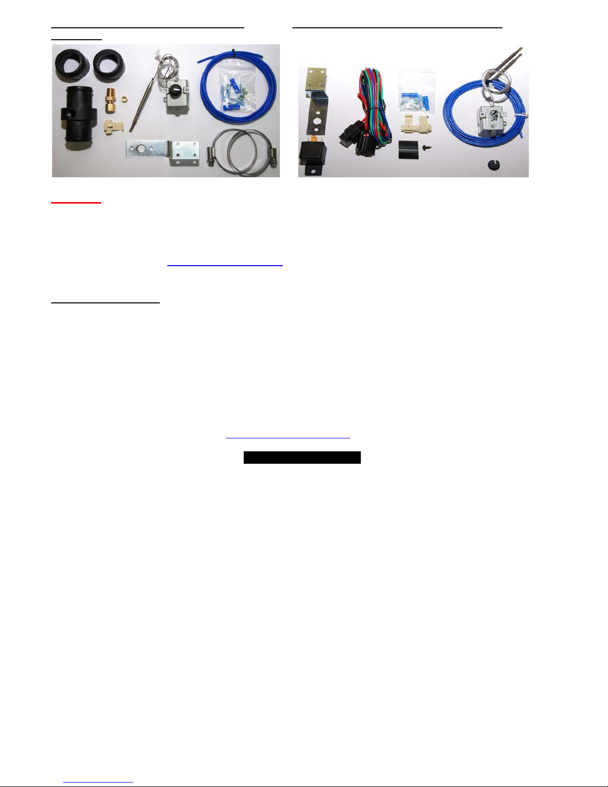
B. KIT REQUIREMENTS:
This kit includes all parts necessary for condenser
cooling. If you wish to cool the vehicle radiator you
should purchase one of Davies, Craig’s Thermatic
Switches Parts: #0401 or #0444 from your retailer or
on line from the Davies, Craig website,
www.daviescraig.com.au. If you wish to cool both
radiator and condenser cores you should purchase a
Thermatic Switch & Relay Kit #0404 which contains
a Thermatic Switch, #0401 and an extra relay and
wiring loom or the Digital Electronic Switch #0444.
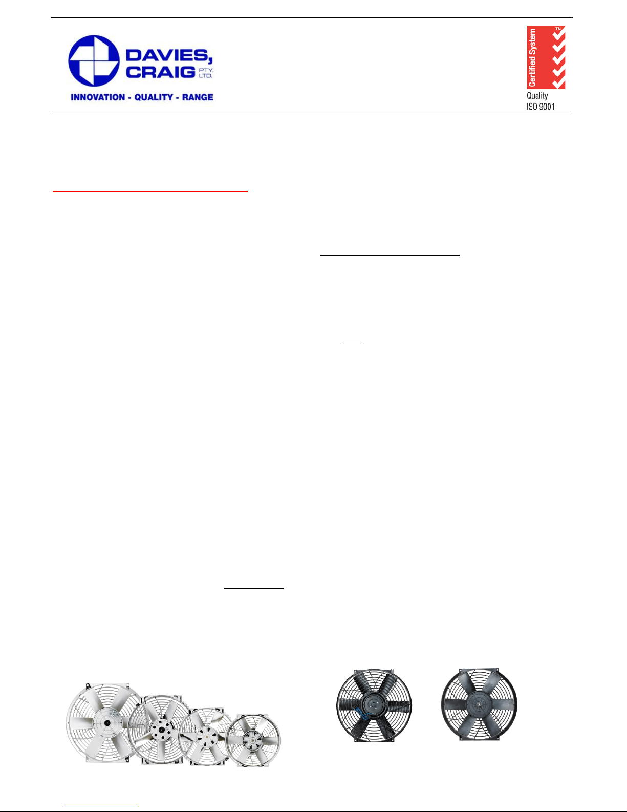
C. FAN ORIENTATION
All Davies Craig fans are reversible and may be
mounted either upstream (in front of
radiator/condenser) or downstream (on the engine
side of the radiator/ condenser).
N.B. ALL THERMATIC FANS ARE FACTORY
ASSEMBLED TO BE MOUNTED UPSTREAM (in
front of radiator/condenser)
if there is insufficient space in front of the
radiator/condenser, the fan may be mounted
downstream, provided four steps are taken before
mounting.
For downstream mounting
(i) Remove the clip or undo the hex nut from the
centre of the fan blade.
(ii) Remove the fan blade from the motor shaft, turn
it over and replace. In every case the instruction,
printed on the blade, ‘this side must face f ront of
vehicle’ or ‘this side must face rear of vehicle’
must be followed.
(iii) Re-secure the fan blade
(iv) Before mounting the fan to the face of the
radiator/condenser, note the direction of the
arrow on the fan blade and when wiring, ensure
the fan rotates in the direction of the arrow in all
cases.
Optimum Thermatic Fan performance (forced air
flow) will be achieved by mounting the fan directly to
the surface of the respective condenser and r adiator
core.
If you are having your fan fitted by a professional,
please ask that these instructions ar e read in f ull and
understood before installation.
Vehicles used for towing caravans and large trailers
may need to retain the standard belt-driven fan, at
least in summer, with the electric fans fitted in the
upstream position.
Air-conditioned cars should be fitted with a
condenser fan such as the 9” or 10” if one is not
already fitted. The 12” and 14” are suitable for
cooling condensers on large sedans and wagons
and the 14”HP or 16” is suitable for condenser
cooling on large commercial vehicles.
77 Taras Avenue
P.O. Box 363
Altona North, Vic 3025 Australia
Phone: +61(0)3 9369 1234
Fax:
+61(0)3 9369 3456
E
-mail: info@daviescraig.com.au
Web: www.daviescraig.com.au
Page 2
P/No:0950 2
D. INSTALLATION OF FANS
There are four stages involved in the installation of
your Davies, Craig Fan(s).
(i) Mounting the fan assembly.
(ii) Installation of the Thermatic Switch.
(Radiator Cooling)
(iii) Wiring.
(iv) Setting the Thermatic Switch.
(Radiator Cooling)
MOUNTING OF FAN ASSEMBLY
CONDENSER COOLING ONLY
1. If you’ve purchased the Thermatic Fan to cool
the A/C condenser, it should be mounted
upstream. GO TO PARAGRAPH 4 (Radiator
Cooling).
RADIATOR COOLING
2. Remove the original belt driven fan and shroud.
After removing fan from the pulley, replace the
bolts in the water pump hub. You may need
washers (not provided) to replace the thickness of
the belt driven fan.
3. Decide which surface of the radiator you wish to
mount the fan(s). If you are fitting two fans it may
be necessary to fit the larger of the t wo upstream
and the smaller downstream, with as little overlap
as possible.
4. Pay particular attention to the markings/arrows
on the fan hub regarding the direction the fan
should face. These instructions must be followed
closely, whether you choose upstream or
downstream mounting. Please note; the direction
of rotation is indicated by the arrow on the fan
hub. Once the fan has been installed the arrow
may not be visible.
5. Position the fan(s) directly on the surface of the
radiator/condenser. Take care that the fan and
shroud does not foul any struts, engine pulleys,
bonnet latches etc., including when the bonnet is
closed.
6. For 8”, 9”, 10” and 12” fans, check that the wires
exit the motor downwards (i.e.: at 6 o’clock), to
ensure any condensation f ormed in the motor can
drain.
7. Depending on the space available and the
presence of a condenser core, you may prefer at
this point to remove the radiator from the vehicle
to ease the fitting procedure.
8. Separate the condenser/radiator fins at the four
points where the mounting bolts are to be passed
through the radiator between the tubes. Use a
pencil or ‘’Phillips head’’ screw-driver to separate
the fins, being careful not to damage the tubes.
9. Fix the fans(s) to the radiator/condenser using the
long bolts and nuts provided, together with the
fibre and steel washers as per above diagram.
NOTE: Long bolts are supplied to accommodate
thick cores. Ensure that the protruding bolts do not
foul any other radiator cores or engine parts. Trim
with bolt cutters if necessary.
11. Before wiring, spin the fan by hand to ensure
free and unobstructed rotation.
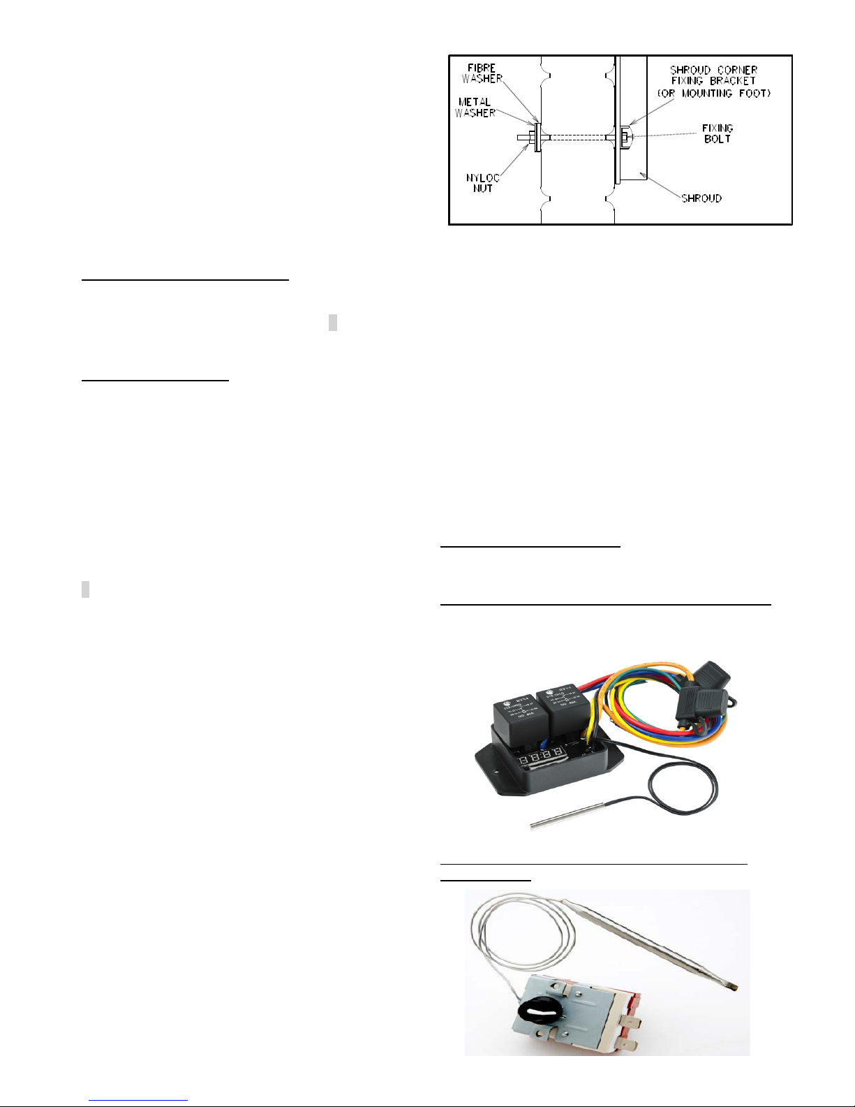
THERMATIC SWITCHES
Davies Craig offers four Thermatic Switches to suit
various Therm atic Fan applications;
The Digital Electronic Thermatic Switch, Part #0444.
This Switch will operate two Thermatic Fans, either
twin fans for the radiat or core or one on the radiator
and one on the condenser core. (12 Volt Only)
The Mechanical Thermatic Switch, Part #0401 –
suit 12v & 24v
Page 3
P/No:0950
3
The Mechanical Thermatic Switch, Combo The Mechanical Thermatic Switch, Part #0404
Part #0400
WARNING: Do not use the vehicle’s engine management system or wiring connected to the management
system as an ignition source as it may cause failure of the management system and/or the electrical system.
The ignition source must be a steady positive supply of 12 or 24V DC.
If in doubt about any aspect of these instructions consult your retailer or Davies, Craig P/L direct on:
(03) 9369-1234 or e-mail info@daviescraig.com.au
IMPORTANT NOTES
Four Wheel Drives - monitor engine temperature c losely when using off -road at low forward speeds in h ot weather. If
you wish, supplement cooling with the Davies, Craig EWP – Electric Water Pumps.
Towing of heavy boats and caravans can cause overheating. Thermatic fans can help to solve this, particularly if
mounted in front of the radiator and, if necessary, used in conjunction with the standard belt driven fan, or an EWP.
Air-conditioned vehicles normally require a condenser fan in conjunction with the standard belt driven fan.
It is possible to eliminate the belt driven fan all together by using a combination of Thermatic Fans suitable to your
vehicle, as set out on the ‘Mode l Sel ec tio n G uide’, w ith an air-conditioner condens er f an. This will gi ve you a l l the benefits
of electric cooling.
If overheating persists there may not be enough coolant f lo w. The D a vies Cr ai g EWP (Electric Water Pump) will sol ve the
problem. More details are on our website.
www.daviescraig.com.au.
TROUBLE SHOOTING
The following notes are de signed to help you overcome the mos t common problems experienced by custom ers with
Thermatic fans:
1. FAN RUNS NORMALLY BUT ENGINE OVERHEATS, CHECK:
a. Correct model is fitted
b. Thermal Switch is set correctly
c. Fan blade facing the right way and rotating in direction of the arrows and in accordance with chart.
d. Fan/s connected to full 12V power source.
e. Fan too far from face of radiator
f. Other cooling system problems
2. FAN RUNS WHEN CAR TRAVELLING AT MEDIUM TO HIGH SPEEDS, CHECK:
a. Adjustment of thermal switch
b. Is the vehicle towing?
c. Other cooling system faults
3. FAN DOES NOT RUN OR RUNS SLOWLY, CHECK:
a. Fuses
b. Adjustment of thermal switch –set too high!
c. Wiring integrity
d. Connect motor(s) directly to battery then trace wiring towards switch if motor(s) runs.
e. Check earth connections.
Page 4

P/No:0950
4
FAN ROTATION AND POLARITY
DAVIES CRAIG
Fan Models
UPSTREAM
DOWNSTREAM
DCSL-8
DCSL-9
DCSL-10
DCSL-12
DCSL-16
DCSL-14HP
MOTOR - EARTH
WIRE
BLUE or RED
BLACK
FAN ROTATION
DCSL-14
MOTOR-EARTH
WIRE & FAN
ROTATION
BLACK
BLUE or RED
NOTE: Rotation as viewed from front of vehicle must be clockwise in all cases, except DCSL-14
which rotates anti-clockwise.
Colour of motor earth lead depends on fan location upstream or downstream.
The two terminals on the thermal swit ch are equivalent. It does n ot matter which goes to ignition and
which goes to the relay. When the switch closes it just connects the two terminals.
WARRANTY: We warrant that for a period of two years or 2000 hours continuous run ning
(whichever is the lesser) from the date of purchase, we shall carry out, free of cost, any
repairs that are reasonably necessary to correct any fault in the operation of your Electric
Fan provided that such a fault is directly attributable to a defect in the workmanship or
materials used in the manufacture of the part(s) and is not due to installation other than
described in these instructions. Labour and consequential costs are excluded.
Register Warranty at: www.daviescraig.com.au
RADIATOR
Page 5

P/No:0950
5
Page 6

P/No:0950
6
DAVIES, CRAIG THERMATIC FAN WIRING DIAGRAMS WITH #0401 S WITCH
1
ONE FAN, CONDENSER ONLY
1
BLUE CONNECTOR
(FROM FAN KIT)
2 SELF TAPPER
(FROM FAN KIT)
3 SCOTCHLOCK
(FROM FAN KIT)
4 RING TE RMI NAL
(FROM FAN KIT)
5 FUSE HOLDER & FUSE
(FROM FAN KIT LOOM)
PURCHASE: 1 FAN KIT
2
ONE FAN, THERMATIC ONLY
1
BLUE CONNECTOR
(FROM FAN KIT)
2 SELF TAPPERN
(FROM FAN KIT)
3 SCOTCHLOCK
(FROM FAN KIT)
4 RING TE RMI NAL
(FROM FAN KIT)
5 FUSE HOLDER & FUSE
(FROM FAN KIT LOOM)
6 FEMALE SPADE BLUE
(FROM THERMAL SWITCH KIT)
7 FEMALE SPADE BLUE
(FROM THERMAL SWITCH KIT)
8 COILED BLUE WIRE
(FROM THERMAL SWITCH KIT)
PURCHASE: 1 FAN KIT, 1 THERMAL SWITCH
KIT P/NO: 0401
3
ONE FAN, CONDENSER
AND / OR THERMATIC
1
BLUE CONNECTOR
(FROM FAN KIT)
2 SELF TAPPER
(FROM FAN & THERMAL SWITCH KIT)
3 SCOTCHLOCK
(FROM FAN & THERMAL SWITCH KIT)
4 RING TE RMI NAL
(FROM FAN KIT)
5 FUSE HOLDER & FUSE
(FROM FAN KIT LOOM)
6 FEMALE SPADE BLUE
(FROM THERMAL SWITCH KIT)
7 FEMALE SPADE BLUE
(FROM THERMAL SWITCH KIT)
8 COILED BLUE WIRE
(FROM THERMAL SWITCH KIT)
PURCHASE: 1 FAN KIT, 1 THERMAL SWITCH
& RELAY KIT P/NO: 0404
4
TWIN FANS, THERMATIC ONLY
1 BLUE CONNECTOR
(FROM FAN KITS)
2
SELF TAPPER
(FROM FAN KITS)
3 SCOTCHLOCK
(FROM FAN KITS)
4 RING TE RMI NAL
(FROM FAN KITS)
5 FUSE HOLDER & FUSE
(FROM FAN KITS)
6 FEMALE SPADE BLUE
(FROM THERMAL SWITCH KIT)
7 FEMALE SPADE BLUE
(FROM THERMAL SWITCH KIT)
8 COILED BLUE WIRE
(FROM THERMAL SWITCH KIT)
PURCHASE: 1 FAN KIT, 1 THERMAL SWITCH
KIT P/NO: 0401
5
TWIN FAN, THERMATIC
SINGLE FAN CONDENSER
1 BLUE CONNECTOR
(FROM FAN KITS)
2 SELF TAPPER
(FROM FAN & THERMAL SWITCH KIT)
3 SCOTCHLOCK
(FROM FAN KITS)
4 RING TE RMI NAL
(FROM FAN KITS)
5 FUSE HOLDER & FUSE
(FROM FAN KITS)
6 FEMALE SPADE BLUE
(FROM THERMAL SWITCH KIT)
7 FEMALE SPADE BLUE
(FROM THERMAL SWITCH KIT)
8 COILED BLUE WIRE
(FROM THERMAL SWITCH KIT)
PURCHASE: 2 FAN KITS, 1 THERMAL SWITCH
& RELAY KIT P/NO: 0404
6
TWIN FANS, CONDENSER ONLY
1
BLUE CONNECTOR
(FROM FAN KIT)
2
SELF TAPPER
(FROM FAN KITS)
3 SCOTCHLOCK
(FROM FAN KITS)
4 RING TE RMI NAL
(FROM FAN KITS)
5 FUSE HOLDER & FUSE
(FROM FAN KITS)
PURCHASE: 2 FAN KITS
Note: Colour of motor leads depends on fan location (upstream/downstream)
If in doubt, refer to the rotatio n and polarity chart.
The two terminals on the thermal switch ar e equivalent. It does not matter which goes to the ignition and which
WARNING: ENSURE IGNITION SOURCE IS NOT CONNECTED TO THE ENGINE MANAGEMENT SYST EM
WARNING: ENSURE IGNITION SOURCE IS NOT CONNECTED TO THE ENGINE MANAGEMENT SYST EM
WARNING: ENSURE IGNITION SOURCE IS NOT CONNECTED TO THE ENGINE MANAGEMENT SYST EM
WARNING: ENSURE IGNITION SOURCE IS NOT CONNECTED TO THE ENGINE MANAGEMENT SYST EM
Page 7

P/No:0950
7
Page 8

P/No:0950
8
 Loading...