

Page 1
P/No. 0960
PART NO. 0401 & 0404 - THERMAL SWITCH INSTALLATION INSTRUCTIONS
(12 & 24 VOLT) BEFORE BEGINNING INSTALLATION, READ THESE INSTRUCTIONS FULLY.
Note: For automobile applications, controller terminals marked as “H” & “C” (terminal 6 & 7 in wiring diagram) can be used for either ignition or to the
relay positive. The earth terminal on controller (not shown in wiring diagrams) is not applicable for automobile applications.
INSTALLATION OF THERMAL SWITCH
1. When the engine is cold, remove the top radiator hose at the
radiator end.
2. Mount the Thermal Switch to the bracket using the two small
screws provided. Do not remover the two large screws holding
the thermal switch together. IF THEY ARE REMOVED THE
WARRANTY WILL BECOME VOID.
3. Mount the bracket onto a panel near the radiator so that the
stainless steel bulb will easily reach into the top radiator hose.
Ensure that the adjustment shaft is accessible. Fix the bracket
in place with the two large self-tapping screws provided.
4. Lay the rubber seal along the radiator ferrule and place a
section of the stainless steel capillary of the Thermal Switch
down the groove in the rubber seal. Keep the capillary loosely
coiled and avoid sharp bends. Do not pass the bulb further
down the hose than is necessary as the constant movement of
the engine in relation to the radiator may cause fatigue of the
capillary. The seal and tube may be held in place with
insulation tape.
Fit the hose and clamp so that the clamp is over the centre of
the rubber seal and the clamp screw is in the opposite side of
the tube to the capillary and seal. A good silastic type sealant
may be useful if there is a persistent leak.
5. Top up the radiator with the appropriate coolant.
6. For wiring purposes, please refer to appropriate wiring diagram
overleaf.
WARNING: Do not use the vehicle’s engine management
system or wiring connected to the management system as an
ignition source as it may cause failure of the management
system and/or the electrical system. The ignition source must be
a steady positive supply of 12-24VDC.
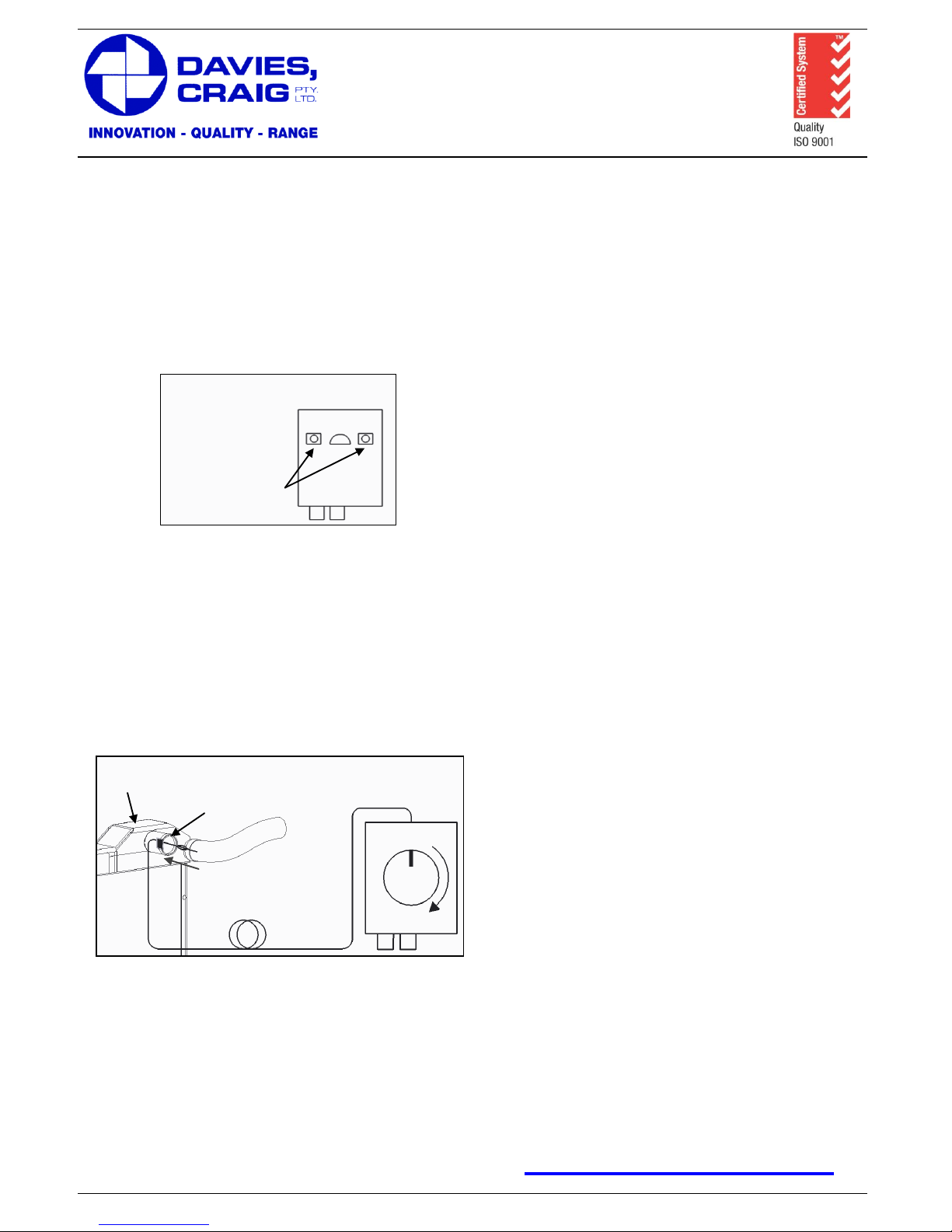
SETTING THE ADJUSTABLE THERMAL SWITCH
1. Install control know on the shaft.
2. Turn on the ignition and rotate the adjustment know anti-
clockwise until it stops. The fan(s) will run if the engine
temperature is above 40°C – if the fan(s) do not cut in,
partially warm the engine to bring the engine temperature into
the range of the Thermal Switch.
3. Check that the fan(s) rotate in the correct direction. If the fan(s)
rotate in the wrong direction, swap the two wires connected to
the motor leads (reversing the polarity).
4. Ensure that all electrical connections are permanent and
properly insulated and that all wiring is fitted so as to avoid
sharp edges and hot parts of the engine.
5. Turn the adjustment know fully clockwise.
6. Run the engine until the engine temperature is about halfway
between “normal highway operating temperature” and “too
hot”. This will indicate a coolant temperature between 5°C and
10°C higher than normal.
7. Immediately turn the adjustment shaft very slowly anticlockwise, just until the fan(s) switch on, and no more.
8. Allow the fan(s) to run long enough to reduce the temperature
by approximately the thickness of the temperature gauge
needle before the Thermal Switch turns the fan(s) off. On a
cool day it should run between 30 and 60 seconds at a time,
on a hot day somewhat longer.
NOTE: If the fan(s) run for more than a few minutes at a time,
turn the adjustment clockwise slightly to increase the cut-in
temperature. The fan(s) must be set to cut-in above normal
operating temperature otherwise they will run more frequently
and for longer periods than necessary, and you may not achieve
all the benefits of electric fan cooling.
NOTE: Remember that coolant under pressure in a radiator
boils at about 118°C.
FAILURE TO COMPLY WITH ALL THE INSTRUCTIONS OR
TAMPERING WITH THE PRODUCT MAY INVALIDATE THE
MANUFACTURERS WARRANTY.
If in any doubt about any of these instructions, consult your
retailer or DAVIES, CRAIG direct on +61 (3) 9369 1234.
WARRANTY: We hereby guarantee that for a period of 2 years
from the date hereof we shall replace your Electronic Thermal
Switch, if it is faulty, provided that such a fault is directly
attributable to a defect in workmanship or materials used in the
manufacture of the Electronic Thermal Switch. Labour and
consequential costs are excluded.
Register Warranty at:
www.daviescraig.com.au
77 Taras Avenue
P.O. Box 363
Altona North, Vic 3025 Australia
Phone: +61(0)3 9369 1234
Fax: +61(0)3 9369 3456
E-mail: info@daviescraig.com.au
Web: www.daviescraig.com.au
40°C
100°C
Radiator Top
Tank
Rubber Seal
Mounting of Thermal
Switch Bracket
Threaded Holes for
Bracket Mounting
Page 2
P/No. 0960
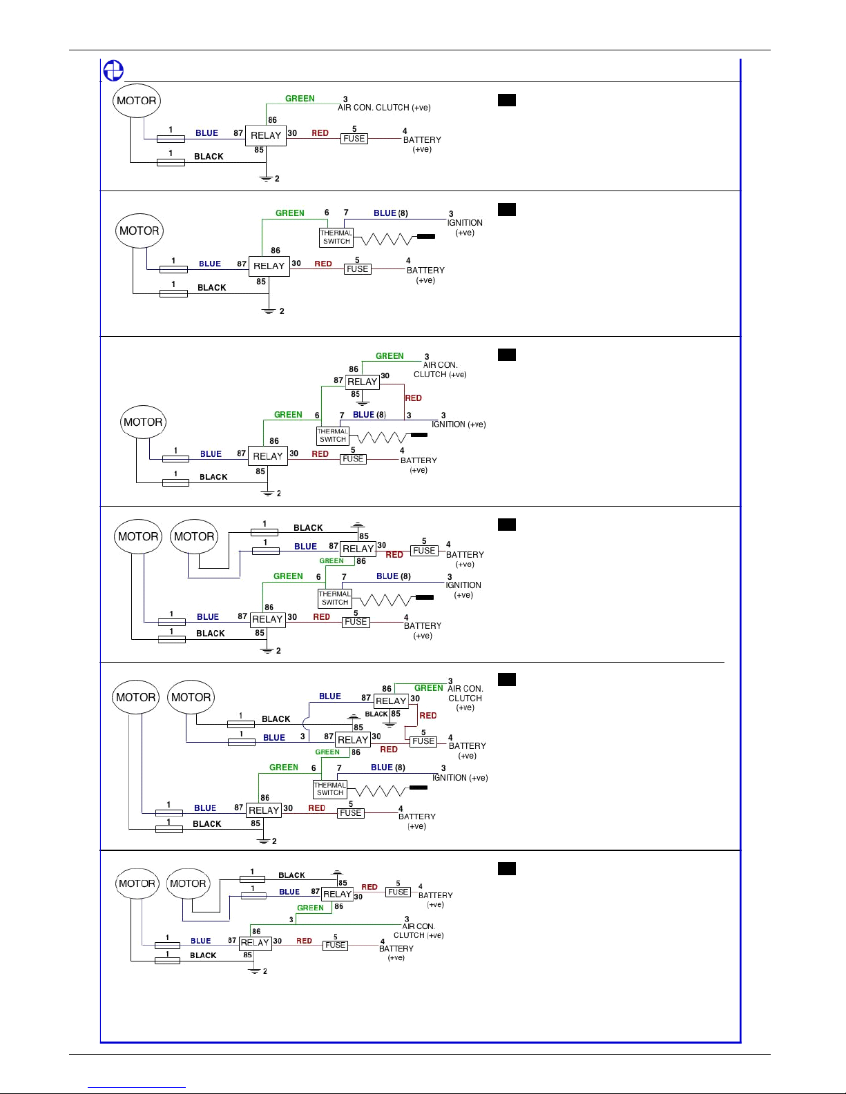
DAVIES, CRAIG PTY. LTD. THERMATIC FAN WIR ING DIAGRAMS
1
ONE FAN, CONDENSER ONLY
1
BLUE CONNECTOR (FROM FAN KIT)
2
SELF TAPPER (FROM FAN KIT)
3
SCOTCHLOCK (FROM FAN KIT)
4
RING TERMINAL (FROM FAN KIT)
5
FUSE HOLDER & FUSE (FROM FAN KIT LOOM)
PURCHASE: 1 FAN KIT
2
ONE FAN, THERMATIC ONLY
1
BLUE CONNECTOR (FROM FAN KIT)
2
SELF TAPPERN (FROM FAN KIT)
3
SCOTCHLOCK (FROM FAN KIT)
4
RING TERMINAL (FROM FAN KIT)
5
FUSE HOLDER & FUSE (FROM FAN KIT LOOM)
6
FEMALE SPADE BLUE (FROM THERMAL SWITCH KIT)
7
FEMALE SPADE BLUE (FROM THERMAL SWITCH KIT)
8
COILED BLUE WIRE (FROM THERMAL SWITCH KIT)
PURCHASE: 1 FAN KIT, 1 THERMAL SWITCH
KIT P/NO: 0401
3
ONE FAN, CONDENSER
AND / OR THERMATIC
1
BLUE CONNECTOR (FROM FAN KIT)
2
SELF TAPPER (FROM FAN & THERMAL SWITCH KIT)
3
SCOTCHLOCK (FROM FAN & THERMAL SWITCH KIT)
4
RING TERMINAL (FROM FAN KIT)
5
FUSE HOLDER & FUSE (FROM FAN KIT LOOM)
6
FEMALE SPADE BLUE (FROM THERMAL SWITCH KIT)
7
FEMALE SPADE BLUE (FROM THERMAL SWITCH KIT)
8
COILED BLUE WIRE (FROM THERMAL SWITCH KIT)
PURCHASE: 1 FAN KIT, 1 THERMAL SWITCH
& RELAY KIT P/NO: 0404
4
TWIN FANS, THERMATIC ONLY
1
BLUE CONNECTOR (FROM FAN KITS)
2
SELF TAPPER (FROM FAN KITS)
3
SCOTCHLOCK (FROM FAN KITS)
4
RING TERMINAL (FROM FAN KITS)
5
FUSE HOLDER & FUSE (FROM FAN KITS)
6
FEMALE SPADE BLUE (FROM THERMAL SWITCH KIT)
7
FEMALE SPADE BLUE (FROM THERMAL SWITCH KIT)
8
COILED BLUE WIRE (FROM THERMAL SWITCH KIT)
PURCHASE: 1 FAN KIT, 1 THERMAL SWITCH
KIT P/NO: 0401
5
TWIN FAN, THERMATIC
SINGLE FAN CONDENSER
1
BLUE CONNECTOR (FROM FAN KITS)
2
SELF TAPPER (FROM FAN & THERMAL SWITCH KIT)
3
SCOTCHLOCK (FROM FAN KITS)
4
RING TERMINAL (FROM FAN KITS)
5
FUSE HOLDER & FUSE (FROM FAN KITS)
6
FEMALE SPADE BLUE (FROM THERMAL SWITCH KIT)
7
FEMALE SPADE BLUE (FROM THERMAL SWITCH KIT)
8
COILED BLUE WIRE (FROM THERMAL SWITCH KIT)
PURCHASE: 2 FAN KITS, 1 THERMAL SWITCH
& RELAY KIT P/NO: 0404
6
TWIN FANS, CONDENSER ONLY
1
BLUE CONNECTOR (FROM FAN KIT)
2
SELF TAPPER (FROM FAN KITS)
3
SCOTCHLOCK (FROM FAN KITS)
4
RING TERMINAL (FROM FAN KITS)
5
FUSE HOLDER & FUSE (FROM FAN KITS)
PURCHASE: 2 FAN KITS
Note: Colour of motor leads depends on fan location (upstream/downstream)
goes to the relay. When the switch closes it connects the two terminals.
If in doubt, refer to the rotation and polarity chart.
The two terminals on the thermal switch are equivalent. It does not matter which goes to the ignition and which
WARNING: ENSURE IGNITION SOURCE IS NOT CONNECTED TO THE ENGINE MANAGEMENT SYSTEM
WARNING: ENSURE IGNITION SOURCE IS NOT CONNECTED TO THE ENGINE MANAGEMENT SYSTEM
WARNING: ENSURE IGNITION SOURCE IS NOT CONNECTED TO THE ENGINE MANAGEMENT SYSTEM
WARNING: ENSURE IGNITION SOURCE IS NOT CONNECTED TO THE ENGINE MANAGEMENT SYSTEM
 Loading...