

David White L6-20N, LT6-900N Owner's Manual
L6-20N Level and
LT6-900N Level-Transit
10
60
70
80
90
80
70
60
20
20
10
10
10
10
20
20
30
30
40
40
50
50
60
60
70
80
90
80
70
60
50
40
30
20
10
10
20
30
40
50
60
70
80
90
80
70
60
50
50
40
40
30
30
20
20
10
10
20
20
30
30
40
40
50
50
60
60
70
80
90
80
70
60
50
40
30
20
10
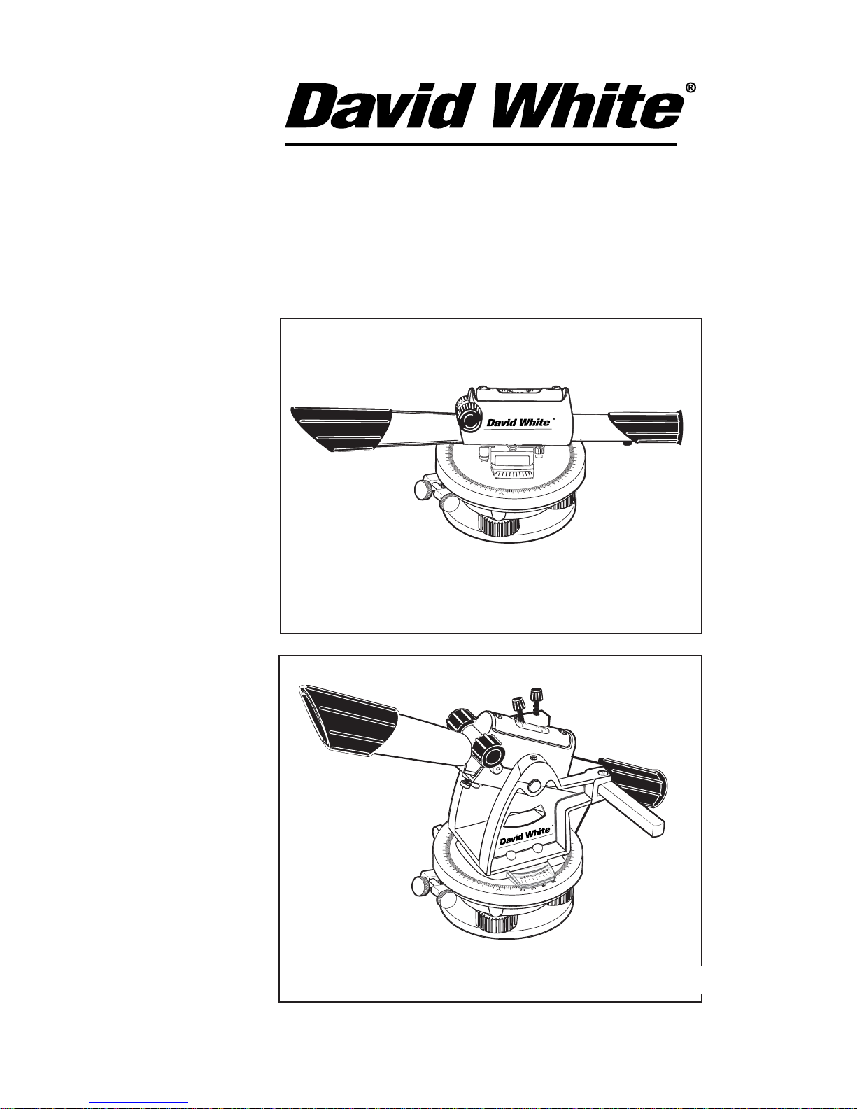
L6-20N Level (Model 44-8824)
LT6-900N Level-Transit (Model 44-8834)
For customer service, call (815) 432-9200
L6-20N / LT6-900N Owner's Guide
00-8830-810

With David White
your sights are set
on precision and accuracy.
Congratulations! You’ve purchased a David White builder/contractor
instrument, American-made and known throughout the world for
precision and accuracy.
The purpose of this booklet is to acquaint you with the instrument,
its components, proper care and handling.
Our levels and level-transits are constructed to withstand
extremely rugged field use. Like all precision instruments,
however, they should be treated with reasonable care to
prolong life and accuracy.
Quality and innovation since 1900.
All instruments are adjusted when they are shipped from the
factory. It is the customer’s responsibility to check and to ensure
instruments are adjusted prior to using.
David White is not responsible for errors caused by instruments
that are out of adjustment.
Contact your distributor, dealer or David White for
information on the nearest facility to check if your instrument
is properly adjusted. Some customers may choose to check
the instrument themselves. This can be done by following
the “Checking for Calibration” instructions at the back of this
manual. All actual adjustments must be done by a qualified
service facility.
All specifications are subject to change without notice.

Specifications
Meridian L6-20N Level
Meridian LT6-900N Level-Transit
Optimum sighting range: Recommended job range up to 200 feet.
Accuracy range:
Recommended for jobs requiring accuracy within
1/4"
at 75 feet.
TELESCOPE
Power
22X
Length 10.5" (26.5cm)
Minimum Focus 4 ft. (1.2m)
Aperture .75" (19mm)
Field of View 2' @ 100' (.6m @ 30m)
No. of Lenses 6
HORIZONTAL CIRCLE
Graduation Diameter 3.62" (92mm)
Graduations Each 1°
Numbers Each 10°, 0-90-0°
Vernier Double direct to 15 min.
VERTICAL ARC (LT6-900N only)
Graduations Each 1°
Numbers Each 10°, 45-0-45°
CENTER Planar bearing
LEVEL VIAL 10 min. per 2mm
WEIGHT L6-20N LT6-900N
Instrument only 3.25 lbs. (1.5kg) 4.5 lbs. (2.0kg)
Instrument, case,
3 oz. plumb bob 6 lbs. 6 oz. (3kg) 7 lbs. 10 oz. (4kg)
CASE Double-walled polyethylene
TRIPOD 5/8 x 11 JIS
2
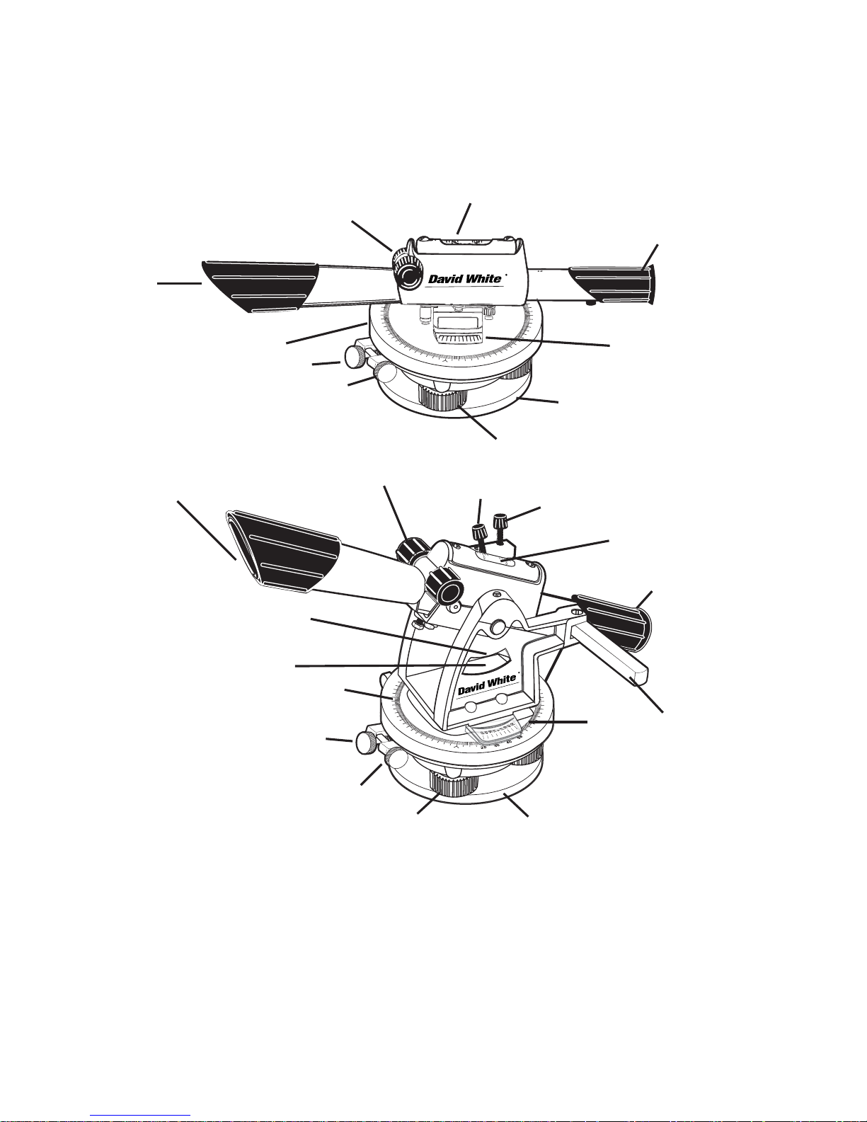
General Description
Meridian L6-20N Level
Meridian LT6-900N Level-Transit
10
20
30
40
50
60
70
80
90
80
70
60
50
50
40
40
30
30
20
20
10
10
20
20
30
30
40
40
50
50
60
60
70
80
90
80
70
60
50
40
30
20
10
10
60
70
80
90
80
70
60
20
20
10
10
10
10
20
20
30
30
40
40
50
50
60
60
70
80
90
80
70
60
50
40
30
20
10
1. Telescope objective lens 9. Telescope lock lever
2. Eyepiece 10. Vertical arc
3. Focusing knobs 11. Vertical arc pointer
4. Instrument level vial 12. Vertical clamp
5. Horizontal graduated circle 13. Vertical tangent
6. Horizontal vernier 14. Three leveling screws
7. Horizontal clamp 15. 5/8 x 11 JIS threaded base
8. Horizontal tangent
1.
1.
5.
5.
6.
6.
10.
14.
14.
15.
15.
11.
2.
7.
8.
9.
8.
7.
3.
4.
4.
2.
3.
12.
13.
3

The telescope provides a sharp image magnified 22 times. This means the
object sighted appears 22 times closer than it would with the naked eye.
The telescope features a built-in sunshade which protects the objective
lens (1) and reduces glare.
To focus on an object, sight through the eyepiece (2) and turn the focus-
ing knobs (3) with either right or left hand. Cross hairs are in constant
focus. All focusing is internal. The telescope does not move outward or
inward as objects are focused. David White Meridian instruments use the
smooth precision of a rack and pinion mechanism for focusing. Focus
range is from four feet to infinity. For closer focus, turn the knob clockwise.
For farther focusing, turn counterclockwise.
The instrument leveling vial (4) is protected by a strong, die-cast casing,
and is graduated to facilitate centering the bubble.
The horizontal circle (5) can be rotated for easy angle setting and read-
ing and is divided in quadrants (0-90°). The circle is marked by degrees
and numbered every 10 degrees.
The horizontal vernier (6) permits dividing whole degrees into fractions of
1/4° (15 minutes). See page 9 for circle and vernier reading instructions.
Approximate horizontal sightings are held firmly in place by means of a
clamp (7). Then, precise horizontal settings can be made with the tangent
(8). The clamp must be hand tightened in order for the tangent to function.
(THE FOLLOWING INDENTED PARAGRAPHS APPLY TO THE LT6-900N
LEVEL-TRANSIT ONLY.)
The Meridian Level-Transit is a combination instrument. Its telescope moves up and down 45 degrees, and rotates 360 degrees, to
measure vertical and horizontal angles.
The telescope lock lever (9) must be in a closed position when
the instrument is to be used as a level; open when used as a
transit for vertical sightings. It is shown in the open position.
The vertical arc (10) is divided in degrees and numbered every 10
degrees up to 45 degrees, for both upward and downward angles,
and has an adjustable index pointer (11).
The vertical clamp (12) holds the telescope at a vertical angle.
Fine vertical settings can be made with the vertical tangent (13).
The vertical clamp must be hand tightened before the tangent will
function.
Both the L6-20N and LT6-900N have three leveling screws (14) for leveling the instrument. The instrument is mounted to the tripod by screwing the
tripod stud into the 5/8 x 11 JIS threaded base (15).
4
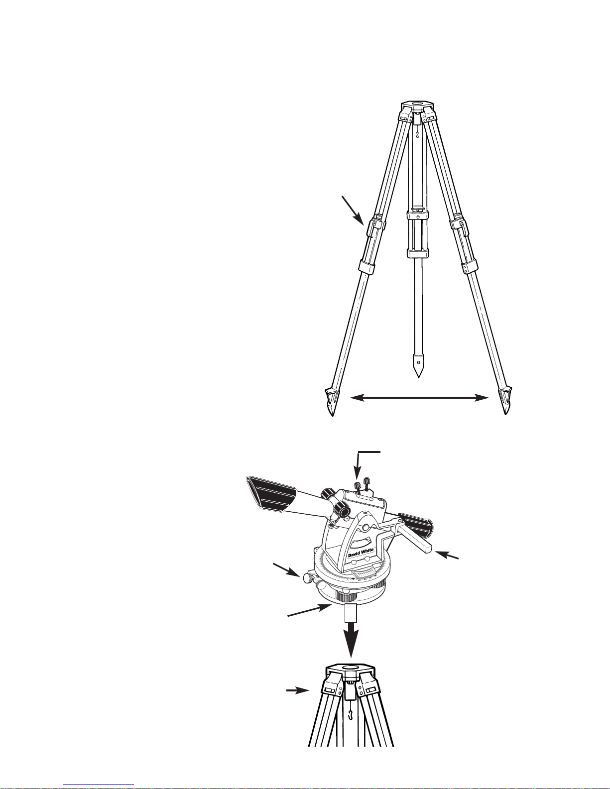
Setting up your instrument
Each of the following steps is
important in preparing to use your
instrument.
1. These instruments must be
used with a 5/8 x 11 JIS thread
tripod. For easiest setup and best
operating results, it is recommended that the David White tripod is
used. It is important that the tripod
is set up firmly. Make sure that the
tripod points are well into the
ground.
When setting up on a smooth floor
or paved surface, secure the points
of the legs by chipping the concrete, attaching chains between the
legs, or putting a brick in front of
each leg. If setting up in dirt, apply
your full weight to each leg to prevent settlement.
Check the tripod legs. They should
have about a 3 foot spread, posi-
tioned so the top of the tripod
head appears level.
If using a tripod with
adjustable legs, be
sure the leg levers are
securely tightened.
10
60
70
80
90
80
70
60
20
20
10
10
10
10
20
20
30
30
40
40
50
50
60
60
70
80
90
80
70
60
50
40
30
20
10
1. Loosen clamp
3. Three
screw
leveling
4. Hand tighten
tripod mounting
stud
1A. Loosen
clamp
2.Close lock
lever
5
3 feet
Lift
lever to
release
leg.
 Loading...