

David White AL8-22, AL8-28, AL8-32, AL8-26 Instruction Manual
IInnssttrruuccttiioonn MMaannuuaall
MMaannuuaall ddee IInnssttrruucccciioonneess
MMaannuueell dd’’IInnssttrruuccttiioonnss
MMaannuuaallee ddii IIssttrruuzziioonnii
BBeeddiieennuunnggssaannl
leeiittuunngg
IInnssttrruuççõõeess ddee UUttiilliizzaaççããoo
INSTRUCTION MANUAL
Automatic Level AL8 Series
Models
AL8-22
AL8-26
AL8-28
AL8-32
®
AL8 AutoLevel • 32 • AL8 AutoLevel
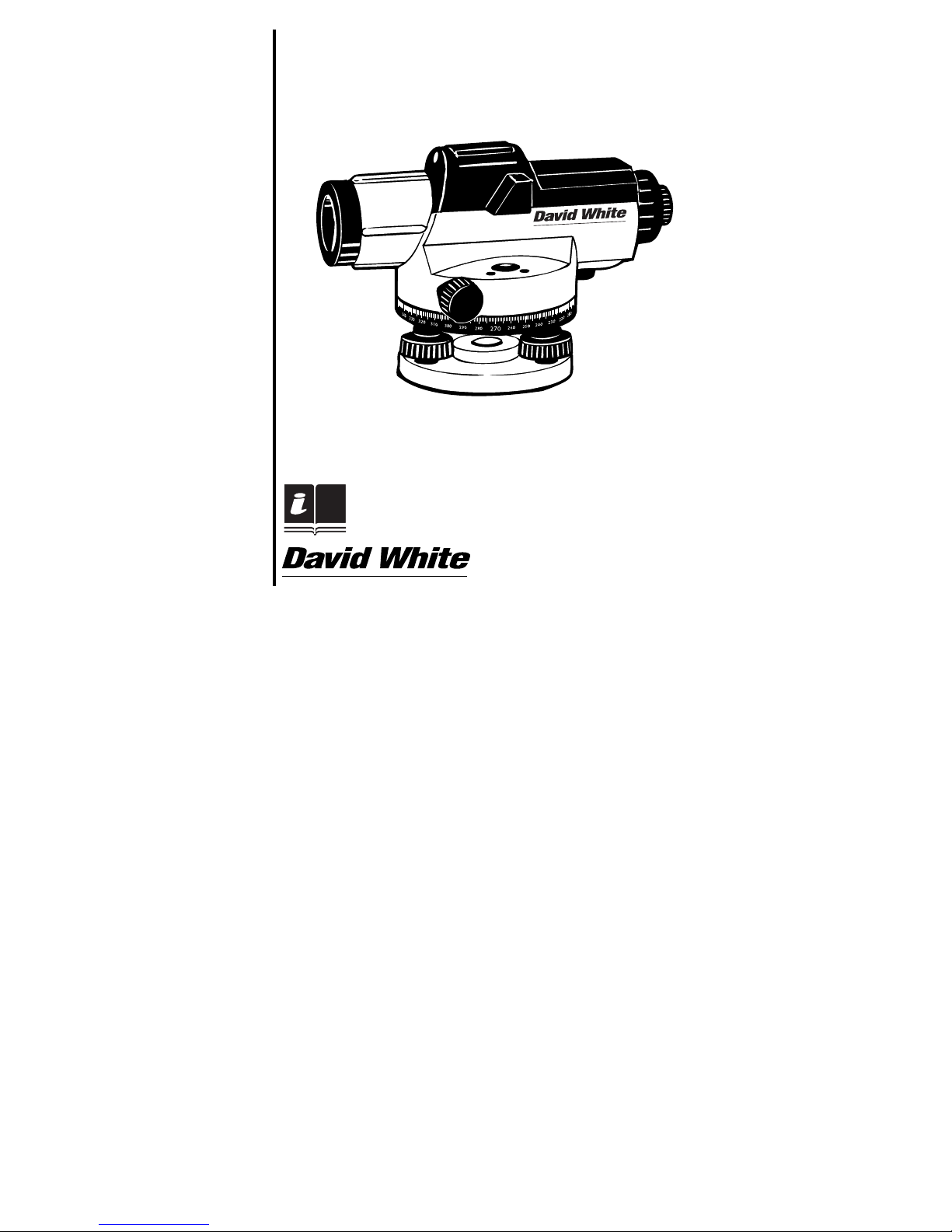
FEATURES (FIG. 1)
1. Base Plate
2. Horizontal Circle 8. Horizontal Drive Screw
3. Horizontal Circle Reference Mark 9. Leveling Screw
4. Compensator Lock 10. Circuclar Bubble Vial
5. Focusing Knobs 11. Vial Sighting Prism
6. Optical Peep Sight 12. Eyepiece Cover
7. Sunshade / Objective Lens 13. Eyepiece Focusing Knob
FEATURES
• Wire-hung, magnetically dampened compensator for optimum range and accuracy.
• Compensator lock protects instrument during transport or storage; the lock can also be
used as a handy compensator checking tool.
• Large effective aperture and minimum focus of 0.3 m.
• Top-mounted optical peep-sight for quick reference.
• Large, easy-to-use precise focusing knob.
• Easy-to-read horizontal circle.
• Prism for easy bubble viewing.
• Sealed, dust-protected leveling screws.
• Water resistant, sealed construction plus sunshade for use in various weather conditions.
• Fine adjustment knobs on left and right sides with friction-braked rotation, endless
horizontal drive.
• 1:100 stadia for distance estimation.
• 5/8” x 11 threads to fit standard tripods.
INTRODUCTION
Thank You for purchasing one of our Automatic Levels.
This manual includes specifications for the AL8 series auto level. This instrument was carefully
inspected and calibrated within tight tolerances before shipment. We properly package the
instruments for shipment, but we cannot control how the package is handled during shipment. We
advise that you check the instrument using the test shown in the Chapter “Line-of-Sight” before
using. “Measure Twice, Cut Once”...
6
FFiigg.. 11
22aa
22bb
FFiigg.. 22
5
4
2
1
7
8
9
EN
11
10
12
13
3

Angle measurement
As shown in Fig. 5, sight point A and rotate the horizontal circle until the reference mark is on “0”.
Rotate the level and sight point B; the reference mark will indicate the angle between A and B.
CALIBRATION
Your Automatic Level has been factory calibrated; however, you should occasionally check your
level for errors caused by shipment or rough handling.
Compensator lock button
Check the compensator for proper operation before use or anytime the operation of the instrument
is in question. Push and release the compensator lock button to shake the compensator. The
compensator should return to the exact horizontal position sighted before the lock button
was pressed.
Circular bubble vial
Center the vial bubble using the leveling screws, then rotate the instrument 180°. The bubble
should remain centered (Fig. 6). If the bubble moves out of center, the vial needs adjustment (Fig.7).
Turn the leveling screws to bring the bubble halfway to center (Fig. 8). Using the Allen wrench, turn
the two vial adjustment screws to center the bubble (Fig. 9).
Repeat the above procedure until the bubble remains centered when the level is rotated 180°.
Line-Of-Sight
The line-of-sight needs to be horizontal within 3 mm of level to be accurate.
Set up and level the instrument on a tripod midway between two leveling rods set approximately
30m to 50m apart. Sight rods A and B; the height readings are a1 and b1 (Fig. 10). The value “H” is
equal to (a1 – b1). Move the instrument to within 6 feet (2m) of rod A and re-level. Again sight rods
A and B; these height readings are a2 and b2 (Fig. 11).
If a1 – b1 = a2 – b2 = H, the line-of-sight is horizontal. If not, the level should be adjusted as follows.
Because the instrument is set halfway between A and B, any error in the line-of-sight causes both
readings to be erroneous by the same amount. Error “e” cancels out, so the value a1 – b1 = H is
correct. Therefore, a2 – H = b3, the adjusting value.
To adjust, unscrew the eyepiece cover. Turn the adjusting screw with the adjusting pin (Fig. 12)
until the horizontal cross hair gives the reading b3, on rod B. Repeat the above Procedure until
{(a1-b1) – (a2-b2)} </= 3 mm.
AL8 AutoLevel • 5
After doing any job using any instrument, it is advised that you check your work. To check your
work, set up the instrument in a different location from the place where you originally set up
(approx. 16 m) and reshoot a few of your original targets. The new readings should agree with the
first readings.
If the new readings do not agree, you should have the instrument checked by a David White
Authorized Repair Center, or try the
Line-of-sight adjustment.
USING THE INSTRUMENT
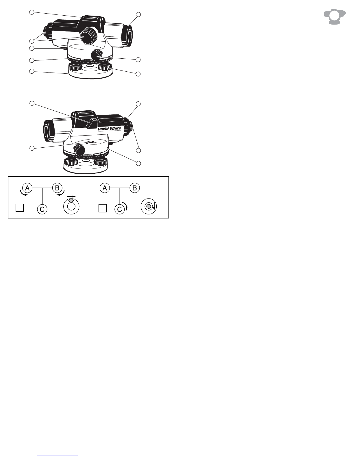
Setting up the instrument and centering the bubble
1. Set up the tripod and attach the level using the tripod mounting screw.
2. Adjust the tripod legs until the tripod head is roughly level. Center the bubble within the vial
by turning the leveling screws as shown in Fig. 2.
2a – Turn screws A and B to move the bubble to the right side.
2b – Turn screw C to center the bubble.
Focusing the instrument
1. Focus the cross hairs (Fig. 3) by pointing the telescope towards a bright background or
holding a white sheet of paper in front of the objective lens, then turning the eyepiece until
the cross hairs are sharp and black.
2. Focus the telescope by locating a target, such as a leveling rod, using the optical peep sight.
Looking through the eyepiece, use the focusing knob to bring the target into sharp focus.
Center the vertical hair within the target using the horizontal drive knobs on either side of
the instrument.
Reading measurements using a leveling rod
Height reading
Read the rod where it is intersected by the horizontal hair. For example, the height reading in Fig. 4
(Fig. 4/a) is 2.0 ft (1,195 m).
Distance measurement
Read the rod where it is intersected by the upper and lower stadia hairs; in Fig. 4 (Fig. 4/a) these
readings are at 1.9 ft and 2.1 ft (1,352 m and 1,038 m). The stadia ratio is 1:100; therefore, the
distance from the instrument to the rod is: (2.1 - 1.9) x 100 = 20 feet - Fig. 4/a (1,352 – 1,038) x 100 = 31,41m.
4 • AL8 AutoLevel

AL8 AutoLevel • 7
MAINTENANCE
Care must be taken to maintain the accuracy of the instrument.
• After each use, the instrument should be wiped clean and kept in its carrying case.
• Remove dust from the lenses with a soft brush or a nonabrasive wipe. Never touch the
lenses with your fingers.
• Store the instrument in a dust-free area with low humidity.
• A bag of silica gel dryer is included with each instrument; if it has stopped working
effectively, bake it to remove moisture or replace with a new bag.
• Any damage to the instrument must be repaired by a
David White Authorized Service Center.
TECHNICAL DATA
MMooddeell AALL88--2222 AALL88--2266 AALL88--2288 AALL88--3322
MMaaggnniiffiicc..::
22 x 26 x 28 x 32 x
LLeevveelliinngg::
1/16”@100’ 1/16”@150’ 1/16”@200’ 1/16”@250’
aaccccuurraaccyy
(1,6mm/30m)(1,6mm/45m) (1,6mm/60m)(1,6mm/75m)
WWoorrkkiinngg::
200’ 300’ 300’ 350’
rraannggee
(61 m) (91 m) (91m) (107 m)
CClleeaarr oobbjj.. aappeerrttuurree::
36mm 36mm 40mm 40mm
SSeettttiinngg aaccccuurraaccyy::
+/- 0.8” +/- 0.8” +/- 0.5” +/- 0.3”
SSttaannddaarrdd::
2.5mm 2.0mm 1.5mm 1.0mm
ddeevviiaattiioonn
for 1 km double-run leveling
TTeelleessccooppee::
Image: erect Length: 8.3”(210mm) Shortest focusing distance: 1’ (0.3m)
Field of view : 1.5°’ Stadia ratio: 100 Stadia addition: 0
CCoommppeennssaattoorr::
Leveling range: +/- 15’ Magnet dampening: Yes
SSeennssiittiivviittyy ooff bbuubbbbllee::
8’/2mm
CCiirrccllee ggrraadduuaattiioonn::
1° or 1 gon
WWaatteerr rreessiissttaanntt::
Yes
IInnssttrruummeenntt nneett wweeiigghhtt::
1.7kg (3.7lbs)
MMoouunnttiinngg tthhrreeaadd::
5/8“ x 11
6 • AL8 AutoLevel
WARRANTY
Five Year Warranty. David White, warrants this instrument against defects in material and
workmanship for a period of five years from the date of purchase. Deficient products will be
repaired or replaced at David White's discretion. For warranty and repair information, contact you
local distributor.
For U.S., before returning the instrument to David White, please call
(815) 432-9200 for a Return Authorization Number from our Customer
Service Department.
David White's liability under this warranty is limited to repair or replacement of the unit. Any
attempt to repair the product by other thanfactory authorized personnel will void this warranty.
Calibration and maintenance are the responsibility of the user. Where permitted by law, David
White is not responsible for incidental or consequential damages.
Agents of David White cannot change this warranty. David White is not responsible for damage
resulting from wear, abuse, or alteration of this product. The user is expected to follow ALL
operating instructions.
This warranty may provide you with additional rights that vary by state, province or nation.
IMPORTANT NOTE: The customer is responsible for the correct use and care of the instrument.
Moreover he is completely responsible for checking the job along its prosecution, and therefore for
the calibration of the instrument. Calibration and care are not covered by warranty.
Subject to change without notice

compensador mecánico en lugar que magnético. El resto de datos
técnicos son iguales.
Nuestros instrumentos están controlados y calibrados en fábrica; y al mismo tiempo enviados en
un embalaje muy seguro. Sin embargo no podemos controlar los intrumentos durante el transporte.
Por esta razón se recomienda hacer una prueba de calibración antes de utilizar el instrumento,
siguiendo las instrucciones descritas en el capítulo “ Línea de vista”.
Después de cualquier trabajo con cualquier instrumento, se aconseja comprobar siempre el
trabajo. Colocar el instrumento en un lugar distinto, aproximadamente a 16 m del lugar inicial, y
tomar otra vez algunas de las lecturas iniciales. Estas nuevas lecturas tienen que ser iguales a las
primeras. Si no es así, puede intentar calibrar el instrumento según las indicaciones descritas en
el capítulo “ Línea de vista”, o ponerse en contacto con su proveedor o con un centro de Servicio
Autorizado David White.
UTILIZACIÓN DEL INSTRUMENTO
Ajuste del instrumento y nivelación de la burbuja
1. Colocar el trípode sobre el punto de referencia en el suelo y bloquear las patas. Montar el
nivel en el trípode y atornillarlo.
2. Bloquear las patas del trípode de forma que la cabeza del trípode está bien nivelada.
Centrar la burbuja utilizando los tornillos de nivelación como indicado en la Fig. 2.
2a - Utilizar los tornillos de ajuste A y B para centrar la burbuja esférica de la izquierda
a la derecha.
2b – Utilizar el tornillo de ajuste C para mover la burbuja esférica hacia el centro.
Enfoque del anteojo
1. Apuntar el anteojo a una zona clara o sujetando un papel blanco enfrente del objetivo, y
mover el ocular hasta que el retículo esté bien enfocado (Fig. 3).
2. Enfocar el telescopio localizando un objeto, por ej. una mira con la ayuda del punto de mira.
Mirando a traves del ocular, utilizar el enfoque del objetivo para enfocar la mira. Centrar el
hilo vertical dentro del objeto, utilizando uno de los tornillos de movimiento horizontal.
Lecturas de la mira
Medición de alturas
Tomar la lectura de la mira en el punto donde el hilo horizontal la atraviesa. Por ejemplo, en la Fig.
4 (Fig. 4/a) la medición de la altura es 2.0 pies (1,195 m).
AL8 AutoLevel • 98 • AL8 AutoLevel
DESCRIPCIÓN DE LAS PARTES (FIG. 1)
1. Base 2. Círculo horizontal
3. Referencia para la
graduación horizontal 4. Bloqueo del compensador
5. Enfoque del objetivo 6. Mira del objetivo ó punto de mira
7. Protector solar del ocular 8. Tornillos de movimiento horizontal
9. Tornillos de nivelación 10. Nivel esférico
11. Visor del nivel esferico 12. Protección del ocular
13. Enfoque del ocular
CARACTERISTICAS
• Péndulo compensador suspendido de amortiguación magnética provee gran estabilidad
y precisión.
• El bloqueo del compensador protege el instrumento durante el
transporte; el bloqueo se puede también utilizar para comprobar el
funcionamiento del compensador.
• Gran apertura efectiva y distancia de enfoque mínima de 0,3 m.
• Punto de mira puesto sobre el telescopio.
• Círculo horizontal exterior visible.
• Visor del nivel esferico
• Tornillos de nivelación protegidos contra agua y polvo
• Resistente al agua y al polvo
• Tornillos de movimiento fino situados a ambos lados con rotación
frenada por fricción, rotación horizontal sinfín.
INTRODUCCIÓN
Gracias por haber escogido uno de nuestros Niveles Ópticos.
Este manual de instrucciones incluye las caracteristicas y la utilización para los niveles ópticos de
la serie AL8. Viene también incluido con la serie 55-SAL, que tiene las mismas specificaciones e
instrucciones de uso, con la excepción que los niveles ópticos de la serie 55-SAL incorporan un
E

MANTENIMIENTO Y CONSERVACIÓN
• Después del uso, limpiar el instrumento utilizando un paño suave y seco para eliminar la
humedad. - No utilizar ni detergentes ni disolventes agresivos.
• Guardar el nivel en su maletín cuando no vaya a usarlo, en un lugar sin polvo y sin humedad.
• En el maletín hay también una bolsa de SILICA GEL; si el equipo deja de funcionar mucho
tiempo, sáquelo del estuche y sustituya la bolsita de silica.
• Cualquier avería, reparación o calibración ha de ser realizada en un servicio autorizado
David White.
DATOS TÉCNICOS
MMooddeelloo AALL88--2222 AALL88--2266 AALL88--2288 AALL88--3322
AAuummeennttooss::
22X 26X 28X 32X
PPrreecciissiióónn::
1/16”@100’ 1/16”@150’ 1/16”@200’ 1/16”@250’
(1,6mm/30m) (1,6mm/45m)(1,6mm/60m) (1,6mm/75m)
AAllccaannccee::
200 pies 300 pies 300 pies 350 pies
(60 m) (91 m) (91 m) (107 m)
AAppeerrttuurraa
: 36mm 36mm 40mm 40mm
eeffeeccttiivvaa
EExxaaccttiittuudd::
+/-0,8” +/-0,8” +/-0,5” +/-0,5”
ddee eessttaabbiilliizzaacciióónn
PPrreecciissiióónn ddeell::
2,5 mm 2,0 mm 1,5 mm 1,0 mm
ccoommppeennssaaddoorr eenn ddoobbllee nniivveellaacciióónn ddee 11 kkmm
TTeelleessccooppiioo::
Imagen: Directa Longitud: 8 pul. (202 mm) Dist. de enfoque mín.: 1’ (0,3 m)
Campo de visión: 1°20’ Constante estadimétrica: 100 Constante de adición: 0
NNiivveellaacciióónn aauuttoommaattiiccaa::
Margen de compensación: +/-15’ Amortiguación magnética: Si
SSeennssiibbiilliiddaadd nniivveell eessfféérriiccoo::
8’/2 mm
GGrraadduuaacciióónn ddeell cciirrccuulloo hhoorriizzoonnttaall::
cada 1° o 1 gon
RReessiisstteennttee aall aagguuaa::
Si
PPeessoo ssóólloo iinnssttrruummeennttoo::
4 libras (1,8 kg)
RRoossccaa ppaarraa ttrrííppooddee::
5/8”x11
AL8 AutoLevel • 11
Medición de distancia
Tomar la lectura de la mira donde los hilos del retículo de cuña la atraviesan. Por ejemplo, en la
Fig. 4 (Fig. 4/a) esas mediciones son 1.9 y 2.1 pies (1,352 m y 1,038 m). La constante estadimétrica
es 1:100; por consiguiente la distancia entre la mira y el instrumento es (2.1 – 1.9) x 100 = 20 pies –
Fig. 4/a (1,352 – 1,038) x 100 = 31,41 m.
Medición de ángulos
Como indicado en la Fig. 5 apuntar al objetivo “A” y girar el círculo horizontal hasta que la
referencia se encuentre en el punto 0. Luego apuntar al objetivo “B”; la referencia del círculo
horizontal indicará el ángulo que se ha creado entre A y B.
CALIBRACIÓN
Todos los instrumentos están calibrados durante el montaje y control de calidad; sin embargo el
usuario tiene que controlar la calibración a intervalos regulares y también antes de efectuar
medidas importantes, porque los parámetros pueden variar con el tiempo o con el trasporte.
Bloqueo del compensador
Comprobar el correcto funcionamiento del compensador antes del trabajo o cada vez se tenga
duda sobre su correcto funcionamiento. Presionar y soltar el bloqueo para mover el compensador.
El compensador tiene que volver a la misma posición horizontal donde se encontraba antes de
presionar el bloqueo.
Nivel esférico
Centrar la burbuja utilizando los tornillos de nivelación, luego girar el instrumento 200°°. La burbuja
tiene que estar todavía centrada (Fig. 6). En caso contrario, hay que calibrar el nivel esférico (Fig. 7).
Utilizar los tornillos de nivelación para llevar la burbuja a medio camino hacia el centro (Fig. 8).
Utilizando la llave de ajuste que se encuentre en el maletín, girar los dos tornillos para centrar la
burbuja (Fig. 9).
Repetir este procedimiento, hasta que la burbuja permanezca centrada, cuando se gire el
instrumento 200°°.
Línea de vista
La Línea de vista tiene que ser horizontal dentro de 3 mm para ser precisa.
Montar el nivel optico en un trípode a medio camino entre dos miras puestas a una distancia de
aprox. 30 – 50 m. Nivelar el instrumento. Apuntar las miras A y B; las lecturas de la altura son a1 y
b1 (Fig. 10). H es igual a (a1-b1). Mover el instrumento hasta 2 m de distancia de la mira A y volver
a nivelarlo. Apuntar de nuevo las miras A y B; esas lecturas serán a2 y b2 (Fig. 11).
Si a1-b1 = a2-b2 = H, la line-of-Sight está horizontal. En caso contrario ajustar el nivel como sigue.
Como el instrumento está a medio camino entre A y B, el error en la linea visual causa error de
lectura a ambos lados.El error se cancela fuera, con el valor a1-b1 = H es correcto. Por lo tanto
a2 - H = b3, que es el valor de ajuste.
Para calibrar, desattornillar la protección del ocular. Girar el tornillo de ajuste con la llave (Fig. 12),
hasta que el hilo horizontal da la lectura b3 sobre la mira B. Repetir este procedimiento hasta que
{(a1-b1) – (a2-b2)} </= 3mm.
10 • AL8 AutoLevel
 Loading...